Predicted lithium–iron compounds under high pressure
Yuanyuan Zhoua,
Qiang Xua,
Chunye Zhub,
Qian Lic,
Hanyu Liud,
Hui Wang*a and
John. S. Tse*ad
aState Key Laboratory of Superhard Materials, Jilin University, Changchun 130012, China. E-mail: huiwang@jlu.edu.cn; john.tse@usask.ca
bInstitute of Fluid Physics, Academy of Engineering Physics, Mianyang 621900, China
cCollege of Aeronautical Engineering, Binzhou University, Binzhou 256603, China
dDepartment of Physics and Engineering Physics, University of Saskatchewan, Saskatoon, Saskatchewan S7N 5E2, Canada
First published on 29th June 2016
Abstract
Pressure can induce significant changes in atomic and electronic structures and can in some cases even induce compound formation between elements that do not bond under ambient conditions. Here, we have extensively explored the Li–Fe system at high pressure using the effective CALYPSO algorithm in combination with first-principles calculations. Strikingly, our results show that the stoichiometries of LiFe, Li3Fe and Li3Fe2 have stability regimes on a phase diagram. It is found that both LiFe and Li3Fe2 adopted a fully developed three-dimensional framework. With an increasing Li content, a Li bonding pattern evolves from occupying diamond sublattice to armchair chains, and to the host frameworks constructed by 3- and 6-membered planar rings and 4- and 7-membered planar rings in which linear Fe chains are located in small channels. Our findings put forward a further understanding of the crystal structures and electronic properties of Li–Fe compounds at high pressures.
Introduction
Compounds can have greater superior physical properties than each individual end member and have been widely used for engineering and industry.1–5 A class of materials formed from alkali metals and other metals/metalloids has attracted considerable scientific and technological interest.6–11 For example, the CsAu intermetallic is the first proposed ionic compound formed between two metals in which the gold atoms behave as an auride (Au−).6,7 Zintl compounds formed between alkali elements and any post transition metal, such as NaTl, which obey traditional chemical valence rules, had a great impact on the understanding of bonding in the solid state.6,8,9 Among the alkali metals, Li has received special attention. With only a 2s valence electron, Li is regarded as the simplest of all alkali metals. Recently, considerable efforts were made to study lithium alloys/compounds at high pressures for designing novel materials.12–14 For example, LiZn, having a simple stoichiometry of 1![[thin space (1/6-em)]](https://www.rsc.org/images/entities/char_2009.gif) :
:![[thin space (1/6-em)]](https://www.rsc.org/images/entities/char_2009.gif) 1, has been unexpectedly predicted to be the most stable phase in a Li–Zn system at a wide pressure range of 0–100 GPa. The Li atom in this compound is positively charged by transferring the electron to the 4p orbital of the Zn atom. Experimentally, an unexpected formation of Li–Cs alloys has been observed at a very low pressure of above 0.1 GPa. Analysis of the valence charge density shows that electrons are donated from Cs to the Li p orbitals, resulting in a rare formal oxidation state of −1 for Li. These studies indicate the diversity in bonding of the seemingly simple Li element at high pressure and offer the prospect of many more lithium alloys that are of scientific and technological interest. Iron is the most common element on earth and the most widely utilized metal in industry. However, Fe and Li are not mixable at ambient conditions, and whether high pressure will lead to the formation of a Li–Fe alloy is still an open question. Thus, there is a demand to explore the Li–Fe system at high pressure for both structural and electronic properties.
1, has been unexpectedly predicted to be the most stable phase in a Li–Zn system at a wide pressure range of 0–100 GPa. The Li atom in this compound is positively charged by transferring the electron to the 4p orbital of the Zn atom. Experimentally, an unexpected formation of Li–Cs alloys has been observed at a very low pressure of above 0.1 GPa. Analysis of the valence charge density shows that electrons are donated from Cs to the Li p orbitals, resulting in a rare formal oxidation state of −1 for Li. These studies indicate the diversity in bonding of the seemingly simple Li element at high pressure and offer the prospect of many more lithium alloys that are of scientific and technological interest. Iron is the most common element on earth and the most widely utilized metal in industry. However, Fe and Li are not mixable at ambient conditions, and whether high pressure will lead to the formation of a Li–Fe alloy is still an open question. Thus, there is a demand to explore the Li–Fe system at high pressure for both structural and electronic properties.
In the present study, we thoroughly investigated the possible formation and stability of a Li–Fe compound, since iron is the fourth most common element in the Earth's crust. This resulted in several newly predicted stable stoichiometries (Li3Fe, Li3Fe2 and LiFe) with diverse lithium arrangements: triangle, square, hexagon, linear chains, armchair chains (Li3Fe2), diamond sublattice (LiFe) and hitherto unknown planar seven-membered rings. An unusual structural feature of Li3Fe is that Li could form 2D structures constructed by small and large polygons similar to that of the incommensurate phase of group I and II elements.15 Moreover, in addition to the 1D Fe chains running through the large channels, there are electride chains embedded in the small channels. Spin-polarized calculations of the P6/mmm structure resulted in a magnetic state with a residual spin moment of 0.38 μB.
Computational methods
Searches for stable structures of the Li–Fe system under high pressure were carried out via the first-principles swarm structure searching study (CALYPSO)16,17 in combination with VASP code18 based on density functional theory within the generalized gradient approximation with the exchange–correlation19 functional of Perdew, Burke and Ernzerhof, employing the projector augmented-wave (PAW)20 method where 1s22s1 and 3s23p63d64s2 are treated as valence electrons for Li and Fe atoms, respectively. Its validity in rapidly finding the stable ground-state structures has been demonstrated by its applications in various material systems ranging from elements to binary and ternary compounds.2,16,21,22 For crystal structure searches, we used a plane-wave basis set cutoff of 1000 eV and performed the Brillouin zone integration with a Monkhorst–Pack k-point23 grid of spacing 2π × 0.03 Å−1. Iterative relaxation of atomic positions was stopped when all forces were smaller than 0.001 eV Å−1. Phonon calculations were carried out by using a supercell approach24 as implemented in the phonopy code.25 The validity of the pseudopotentials used at high pressures was carefully examined with the full-potential linearized augmented plane-wave method through the WIEN2k package.26Results
Convex hull
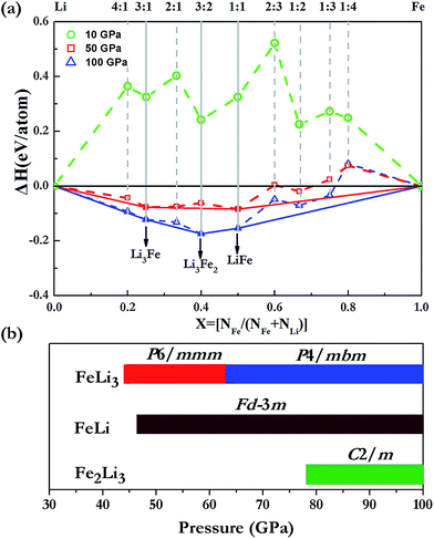
We extensively explored the high-pressure phase stability of various Li–Fe intermetallic compounds via the first-principles swarm structure searching study. Crystal structure predictions are performed at a variety of stoichiometries containing up to 4 formula units (fu) per simulation cell at 10, 50 and 100 GPa. In order to calculate the formation energy of the Li–Fe compounds, the fcc at 10 GPa, I-43d at 50 GPa and Cmcm-24 above 100 GPa structures of Li are used at the corresponding stable pressure ranges.21 For Fe, a hexagonal closet packing (hcp) structure is adopted throughout the explored pressures. As is illustrated in Fig. 1, the Li–Fe compounds are not stable at pressures below 10 GPa. This finding is consistent with the previous knowledge that Li and Fe do not form any stable compounds under ambient conditions. With the pressure increasing to 50 GPa, while most of the phases still lie above the decomposition line, LiFe and Li3Fe appear to be stable, and LiFe is the most stable phase. At 100 GPa, three stoichiometries (Li3Fe, Li3Fe2 and LiFe) are clearly stabilized on the hull, and Li3Fe2 emerges as the most stable phase over the other species. Our simulations provide a useful roadmap for discovering a new type of alloy in Li–Fe systems.Li3Fe
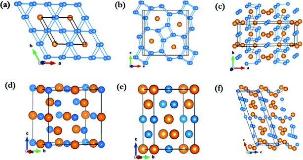
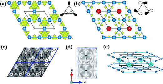
For Li3Fe at 50 GPa, the most stable crystal structure is hexagonal P6/mmm, consisting of one formula unit (1 fu) and constructed 2D planar layers of edge shared regular triangular and hexagonal polygons formed from Li atoms with Fe atoms forming a 1-D chain running along the center of the hexagonal channels (Fig. 2a). The accommodation of Fe in the large open channels between the layers is another indication that the Li–Fe interactions are rather weak. In addition, since there is an odd number in the unit cell, it is possible that the ground state may be ferromagnetic. The spin-polarized calculations resulted in a magnetic state with a residual spin moment of 0.38 μB. Moreover, both the enthalpy and structure are almost identical to the non-spin polarized metallic solution. Additional calculations with a k-point mesh up to 16 × 16 × 16 were performed to ensure the calculated quantities were indeed converged. The magnetic and non-magnetic solutions are found to be almost degenerated with an enthalpy difference of 7 meV fu−1 or 1.7 meV per atom in favour of the ferromagnetic state. To confirm the stability of the ferromagnetic state, additional calculations were performed using a structure model built from two unit cells replicated in the c-axis with initial spins on the two Fe atoms arranged in parallel (ferromagnetic) and anti-parallel (antiferromagnetic) directions. The antiferromagnetic initial spin state was found to collapse to the metallic solution but the ferromagnetic state remained stable.P6/mmm-Li3Fe is a metallic phase in both non- and spin-polarized solutions (Fig. 3a). Examinations of the projected density of states (Fig. 3c and d) show that the majority spin polarization is derived from the Fe atoms. This is quite different from the previous finding in elemental K in which the magnetism originated from the electrides.27 The unpaired electrons are localized on the Fe sites as shown unequivocally from the plot of the net spin density in Fig. 4e. Since Li3Fe has a guest–host structure, it is convenient to compare the electronic structures of Li3Fe and Li3Fe0. Fig. 4a and b show iso-surfaces of the electron localization functions (ELFs)28 for Li3Fe and Li3Fe0. In the absence of Fe atoms, the electrides are strongly localized (ELF values = 0.7) at the centroids of the triangles and midway between two adjacent Li planes. No electron was found to localize at the centers of the large hexagons. This electron distribution is similar to that of the lowest energy molecular orbital of an equilateral triangular “A3”29 from the mixing of Li 2s and 2p. The addition of Fe into the Li framework resulted in significant changes to the electron topology. The maximum ELF value has been reduced to 0.6. An ELF value close to 0.5 should not be taken literally as increasing free electron-like delocalization.30,31 It simply means that, when compared to free electron gas, the kinetic energy at the same position is higher. Apart from a much reduced size of the ELF maxima at the centers of the triangle, the contour surface (ELF = 0.6) of Li3Fe (Fig. 4b) also shows additional features between the Li atoms forming the triangles. The features can also be understood from the filling of the next lowest energy MO of “A3” with anti-bonding character due to the electron transfer from Fe to the Li framework. The band structures of Li3Fe and Li3Fe0 are compared in Fig. 3a and b. If one neglected the “fat” bands primarily of Fe character, the dispersions of the Li dominant electron bands in Li3Fe are similar to those in Li3Fe0, except that the Fermi energy has moved up by ca. 2.1 eV to accommodate the electrons transferred from Fe. At Γ, the “shifted” Fermi level is slightly above the inverted parabolic p-band (in-phase interaction-bonding) and creates an electron pocket in the higher energy anti-bonding bands. The gradient of the Li3Fe charge density in the (parallel) Li plane is displayed in Fig. 4c. According to the quantum theory of atom-in-molecular (QTAIM)32, (3, −1) critical points indicative of covalent bonding (BCP) are found at the center of the localized electrons. Surprisingly, no BCP was found between Li atoms in adjacent layers, and even the interlayer Li–Li separation of 2.031 Å is significantly shorter than the Li–Li distance of 2.147 Å in the plane. This observation follows a trend already observed in high pressure Cs-IV and Cs–V structures, where chemical bonding occurs between Cs in the 2D layers derived from the spatially more extended Cs 5d orbitals due to s–d hybridization leaving insufficient electrons between the Cs planes to form bonds.33,34 This is a common observation in the layer structures of high pressure alkali and alkaline solids.34 BCPs are also found between neighbouring Fe atoms in the 1-D chains running down the hexagonal channels (Fig. 4d), which only weakly interact with the Li framework. Thus, the Fe atoms bonded through the 3d orbitals forming linear nanowires and became slightly ferromagnetic (0.38 μB/Fe) in a spin-polarized calculation. The weak ferromagnetism is the result of the partial electron transfer to the host lattice and small effective exchange energy for switching from antiparallel to parallel spin compared to the axial crystal field of the 1-D chain favouring a low spin arrangement. This observation seems to contradict the Lieb-Mattis theorem35 which states that the spontaneous spin polarization of a one dimensional S = 1/2 chain is forbidden. In this case, inter- and intra-chain interactions (vide supra) led to small residual spin on the Fe atoms and the Fe is not purely S = 1/2.36
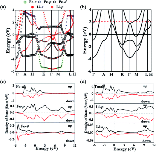 | ||
| Fig. 3 Calculated band structures for non-polarized (a) Li3Fe and (b) hypothetical Li3Fe0. The Fe (c) and Li (d) projected density of states in the ferromagnetic state. | ||
At 100 GPa, Li3Fe was found to be stable in a structure with P4/mbm symmetry (4 formula units per cell; see Fig. 2b) consisting of a planar arrangement of Li formed by edge shared squares and heptagon rings stacked along the c-direction. The Fe atoms are sandwiched between two Li layers parallel to the ab-plane and form 1D linear chains running along the c-axis through the center of the 7-membered rings, which share the same crystal structure of Na3Fe at 150 GPa found in our previous work.37 The presence of heptagonal rings in a crystal structure is highly uncommon and has not been predicted or observed in any high pressure compounds. This structure type, although uncommon, is not without precedent. The same structure has been reported in rare-earth borocarbide (MB2C![[thin space (1/6-em)]](https://www.rsc.org/images/entities/char_2009.gif) :
:![[thin space (1/6-em)]](https://www.rsc.org/images/entities/char_2009.gif) M = Y, Dy and Th) compounds.38–40 In these compounds the 2D-net is made of four- and seven-membered fused rings constructed from boron and carbon atoms. The rare-earth atoms are arranged in a plane between the layers and aligned in a line along the channels formed by the 7-membered rings. The open P4/mbm structure also shares some similarities with self-clathrate structures reported in high pressure crystal structures of group II Rb-IV and Ba-IV. In the group II elements, the “host” 2D plane is composed of fused squares and octagons, while the “guest” Rb or Ba atoms form 1-D chains running through the center of the octagons. Unlike the structure reported here, the “guest” atom positions are not commensurate with the space group of the host framework.
M = Y, Dy and Th) compounds.38–40 In these compounds the 2D-net is made of four- and seven-membered fused rings constructed from boron and carbon atoms. The rare-earth atoms are arranged in a plane between the layers and aligned in a line along the channels formed by the 7-membered rings. The open P4/mbm structure also shares some similarities with self-clathrate structures reported in high pressure crystal structures of group II Rb-IV and Ba-IV. In the group II elements, the “host” 2D plane is composed of fused squares and octagons, while the “guest” Rb or Ba atoms form 1-D chains running through the center of the octagons. Unlike the structure reported here, the “guest” atom positions are not commensurate with the space group of the host framework.
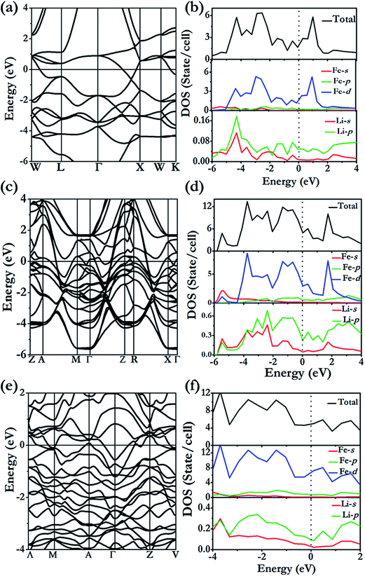
The formation of the 4- and 7-membered Li ring open framework is highly unusual. The apparently complex structure can be easily explained from the consideration of a Li3 building unit composed of two Li of the same type (Li1) and a second Li (Li2) (Fig. 6a). The Li1–Li1 distance is 2.69 Å, slightly longer than the Li1–Li2 bond length of 2.64 Å, and the Li1–Li1–Li2 angle is 122°. The fused 4-and 7-membered ring structure is constructed as follows. Two Li1–Li1 bonds are linked to form a square. The Li2 atoms of the two building units are then bonded respectively to Li1 of different Li3 units. This process is then repeated, forming the 2D-net of the ab plane. From the electronic band structure and the projected densities of states (PDOS) of Li3Fe with a P4/mbm space group (Fig. 5c and d), two distinctive features are noted. First, dispersions of the electron bands are strong in the reciprocal planes in the Li atom layers (e.g. along the Γ → Z direction), but very weak between the layers along the Z → R symmetry direction, indicating that in-plane Li–Li interactions are much stronger than those in the inter-planar direction. Second, a comparison of the PDOS for Li and Fe atoms shows that the individual profiles have little in common and, therefore, the interactions between them are weak and basically ionic. A detailed examination of the PDOS of Li is shown in Fig. 5d. Both Li atoms clearly show strong hybridization of 2s and 2p orbitals from −6 to −2 eV. On the other hand, the individual PDOS profiles of the 2s and 2p orbitals of Li1 from −2 eV to 0 eV are quite different showing that the hybridization is not as strong near the Fermi level. Therefore, we can conclude that the interactions between Li1–Li1 pairs from two Li3 units are derived from the overlaps of sp hybrids from the individual units. This atomic arrangement resulted in the localization of electrons in the middle of the square forming electrides, as in the case of Cs-IV (vide infra).41 Since each Li atom can contribute only one valence electron, not enough to saturate all of the bonds, hybridization led to directional bonding between the sp hybrids. Thus, even the interplanar Li⋯Li contacts are shorter; there is no genuine “covalent bond” between the different layers. This apparently counterintuitive phenomenon has been noted previously in the 2D layered structures of high pressure Cs-IV.41–43 In this structure, Cs utilizes the 5d orbitals (as a result of 6s–5d hybridization) in the bonding, leading to the formation of 2D square-nets with electrons localized (electrides) at the center of the squares. The electron localization function (ELF) provides another indication of the electron charge being removed from Li atoms. The contour surface with ELF = 0.8 (Fig. 6b) that indicates electrons are localized, as electrides, in the interstitials of the square channels and the same plane with Fe atoms (Fig. 6c). Electrides, in which electrons occupy interstitial regions in the crystal and behave as anions, originate from core expulsion by compression and localization of valence electrons in the voids of a crystal.44
LiFe
The stable structure of LiFe has an Fd![[3 with combining macron]](https://www.rsc.org/images/entities/char_0033_0304.gif) m symmetry (NaTl structure) (Fig. 2d) and is thermodynamically stable at pressures ranging from 48.5 GPa to at least 100 GPa. Unlike NaTl, in which the structure consists of only a polymeric (–Tl–)n with a covalent diamond structure with Na+ ions fitted into the anionic lattice, in Fd
m symmetry (NaTl structure) (Fig. 2d) and is thermodynamically stable at pressures ranging from 48.5 GPa to at least 100 GPa. Unlike NaTl, in which the structure consists of only a polymeric (–Tl–)n with a covalent diamond structure with Na+ ions fitted into the anionic lattice, in Fd![[3 with combining macron]](https://www.rsc.org/images/entities/char_0033_0304.gif) m LiFe, both the Li and Fe atoms adopt the covalent diamond structure. In its Zintl phase, moreover, a more interesting feature is that the distances between the Li atoms are the same as the Fe–Fe distance (2.194 Å at 50 GPa, 2.099 Å at 100 GPa). We also identified a metastable structure in I41/amd symmetry at 100 GPa which is energetically competitive (1 meV per atom, Fig. 2e). The electronic structure (Fig. 5a and b) reveals the metallic nature of LiFe in Fd
m LiFe, both the Li and Fe atoms adopt the covalent diamond structure. In its Zintl phase, moreover, a more interesting feature is that the distances between the Li atoms are the same as the Fe–Fe distance (2.194 Å at 50 GPa, 2.099 Å at 100 GPa). We also identified a metastable structure in I41/amd symmetry at 100 GPa which is energetically competitive (1 meV per atom, Fig. 2e). The electronic structure (Fig. 5a and b) reveals the metallic nature of LiFe in Fd![[3 with combining macron]](https://www.rsc.org/images/entities/char_0033_0304.gif) m. A close examination finds that the contribution to the Fermi-level is mainly derived from the d electrons of Fe. Moreover, it shows not only the strong hybridization of the 2s and 2p orbitals of the Li atoms, but that the individual profiles of 2p Li and 3d Fe have much in common below the Fermi-level, indicating that the interactions between Li and Fe in this structure are much more covalent. Both the Fd
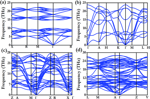
m. A close examination finds that the contribution to the Fermi-level is mainly derived from the d electrons of Fe. Moreover, it shows not only the strong hybridization of the 2s and 2p orbitals of the Li atoms, but that the individual profiles of 2p Li and 3d Fe have much in common below the Fermi-level, indicating that the interactions between Li and Fe in this structure are much more covalent. Both the Fd![[3 with combining macron]](https://www.rsc.org/images/entities/char_0033_0304.gif) m phase and I41/amd phase are dynamically stable (Fig. 7). All the structure information of different stable Li–Fe compound are listed in Table 1.
m phase and I41/amd phase are dynamically stable (Fig. 7). All the structure information of different stable Li–Fe compound are listed in Table 1.
| Structure | (Angstrom, degree) | Atom | Atomic positions (fractional) | ||
|---|---|---|---|---|---|
| Li3Fe P6/mmm | a = 4.2957 | Fe | −0.00000 | −0.00000 | 0.50000 |
| c = 2.0311 | Li | 0.500000 | −0.00000 | −0.00000 | |
| Li3Fe P4/mbm | a = 7.3738 | Fe | 0.31486 | 0.81486 | 0.50000 |
| c = 1.9444 | Li | 0.95272 | 0.17164 | 0.00000 | |
| Li | 0.91116 | 0.41116 | 0.00000 | ||
LiFe Fd![[3 with combining macron]](https://www.rsc.org/images/entities/char_0033_0304.gif) m m |
a = 5.0666 | Fe | 0.50000 | 0.50000 | 0.00000 |
| Li | 0.00000 | 0.50000 | 0.00000 | ||
| Li3Fe2 C2/m | a = 10.2000 | Fe | 0.21042 | 0.50000 | 0.46067 |
| b = 3.9086 | Fe | 0.93872 | −0.00000 | 0.68847 | |
| c = 3.6401 | Li | 0.84088 | 0.22741 | 0.09054 | |
| β = 110.8721 | Li | 0.00000 | 0.50000 | 0.50000 | |
| Li | −0.00000 | 0.50000 | −0.00000 | ||
Li3Fe2
Li3Fe2 becomes stable at 100 GPa and the lowest-energy structure adopts the C2/m symmetry shown in Fig. 2c and f. The predicted C2/m symmetry exhibits a distinctive crystal structure; instead of forming a layered structure in Li3Fe, it has developed a three-dimensional framework, consisting of linear chain and armchair chain bonding patterns of Li atoms. Viewed down from the c axis, the Li armchair chains and Fe zigzag chains stack alternatively with Li–Li distances of 1.778 Å and 1.741 Å and Fe–Fe bond lengths of 2.095 Å, while the linear Li chains and the zigzag Fe chains alternatively arrange along the b axis with a Li–Li bond length equal to 1.820 Å and a Fe–Fe distance equal to 2.160 Å. To further understand the electronic properties, we performed simulations on the electronic band structure and partial density of states (PDOS) of C2/m, as is shown in Fig. 5e and f. The calculated results reveal the metallic features of the structures. The electronic states near the Fermi level are mainly contributed by Fe-3d and a few Fe-3p, Fe-3s, Li-2p,and Li-2s states. The partial DOS profiles for Li-2p and Li-2s are very similar from −4 to −2 eV, indicative of the significant hybridizations between the s and p orbitals of Li thus forming multidirectional bonds between the Li atoms. Moreover, there is clearly a strong hybridization between the 2p orbital of the Li atoms and the 3d orbitals of the Fe atoms from −4 to −2 eV, suggesting a covalent interaction between the Li atoms and Fe atoms. Notice that the 3d states of the Fe atoms appear to be nearly flat from −1 eV to the Fermi level; that is an implication that the 3d electrons of Fe are delocalized. More interestingly, the total density of states of Li3Fe2 is almost constant with increasing energy (from −1 to 0 eV). This is one of the characteristics of a quasi-two-dimensional electronic structure.45Conclusions
In summary, we have produced the first complete pressure-induced phase diagram for LixFe1−x compounds at pressures up to 100 GPa and demonstrated that only LiFe, Li3Fe and Li3Fe2 on Li-rich regimes can be stable and may be experimentally synthesized. Both LiFe and Li3Fe2 adopted a fully developed three-dimensional framework. Rising Li content, however, leads to the formation of host–guest-like structures. The Li3Fe phase at 50 GPa adopts host–guest-like structures with Li sublattices constructed from unusual three- and six-membered planar rings while the “guest” linear Fe chains situated in the large channels donate some of their electrons to the framework and arrange themselves in a ferromagnetic manner with a magnetic moment of 0.3–0.4 μB/Fe. With an increasing pressure up to 100 GPa, rare four- and seven-membered planar Li rings emerge and form the host framework. Electride is identified in the small channels of both P6/mmm and P4/mbm structures of Li3Fe. This work represents a significant step forward in understanding the HP phase diagram of Li–Fe intermetallic compounds, which provides a novel way to search for alloys.Acknowledgements
The authors are thankful for the financial support by Natural Science Foundation of China under Grants No. 11474128, 11474126 and 11534003, China 973 Program under Grant No. 2011CB808200. The calculations were performed in the computing facilities at the High Performance Computing Center of Jilin University.References
- G. Xiao, C. Zhu, Y. Ma, B. Liu, G. Zou and B. Zou, Angew. Chem., 2014, 126, 748–752 CrossRef.
- C. Zhu, Q. Li, Y. Zhou, M. Zhang, S. Zhang and Q. Li, J. Phys. Chem. C, 2014, 118, 27252–27257 CAS.
- G. Yang, Y. Wang and Y. Ma, J. Phys. Chem. Lett., 2014, 5, 2516–2521 CrossRef CAS PubMed.
- J. Feng, R. G. Hennig, N. Ashcroft and R. Hoffmann, Nature, 2008, 451, 445–448 CrossRef CAS PubMed.
- Q. Li, X. Zhang, H. Liu, H. Wang, M. Zhang, Q. Li and Y. Ma, Inorg. Chem., 2014, 53, 5797–5802 CrossRef CAS PubMed.
- A. F. Wells, Structural inorganic chemistry, Oxford University Press, 2012 Search PubMed.
- R. J. Batchelor, T. Birchall and R. C. Burns, Inorg. Chem., 1986, 25, 2009–2015 CrossRef CAS.
- H. G. von Schnering, Angew. Chem., Int. Ed., 1981, 20, 33–51 CrossRef.
- J. D. Corbett, Chem. Rev., 1985, 85, 383–397 CrossRef CAS.
- M. Thackeray, J. Vaughey, C. Johnson, A. Kropf, R. Benedek, L. Fransson and K. Edstrom, J. Power Sources, 2003, 113, 124–130 CrossRef CAS.
- M. Wachtler, J. O. Besenhard and M. Winter, J. Power Sources, 2001, 94, 189–193 CrossRef CAS.
- S. Desgreniers, J. S. Tse, T. Matsuoka, Y. Ohishi and J. J. Tse, Sci. Adv., 2015, 1, e1500669 Search PubMed.
- X. Li, A. Hermann, F. Peng, J. Lv, Y. Wang, H. Wang and Y. Ma, Sci. Rep., 2015, 5, 16675 CrossRef CAS PubMed.
- H. Bi, S. Zhang, S. Wei, J. Wang, D. Zhou, Q. Li and Y. Ma, Phys. Chem. Chem. Phys., 2016, 18, 4437–4443 RSC.
- E. Gregoryanz, L. F. Lundegaard, M. I. McMahon, C. Guillaume, R. J. Nelmes and M. Mezouar, Science, 2008, 320, 1054–1057 CrossRef CAS PubMed.
- Y. Wang, J. Lv, L. Zhu and Y. Ma, Phys. Rev. B: Condens. Matter Mater. Phys., 2010, 82, 094116 CrossRef.
- Y. Wang, J. Lv, L. Zhu and Y. Ma, Comput. Phys. Commun., 2012, 183, 2063–2070 CrossRef CAS.
- G. Kresse and J. Furthmüller, Phys. Rev. B: Condens. Matter Mater. Phys., 1996, 54, 11169 CrossRef CAS.
- J. P. Perdew, K. Burke and M. Ernzerhof, Phys. Rev. Lett., 1996, 77, 3865 CrossRef CAS PubMed.
- G. Kresse and D. Joubert, Phys. Rev. B: Condens. Matter Mater. Phys., 1999, 59, 1758 CrossRef CAS.
- J. Lv, Y. Wang, L. Zhu and Y. Ma, Phys. Rev. Lett., 2011, 106, 015503 CrossRef PubMed.
- H. Wang, S. T. John, K. Tanaka, T. Iitaka and Y. Ma, Proc. Natl. Acad. Sci. U. S. A., 2012, 109, 6463–6466 CrossRef CAS PubMed.
- H. J. Monkhorst and J. D. Pack, Phys. Rev. B: Condens. Matter Mater. Phys., 1976, 13, 5188 CrossRef.
- K. Parlinski, Z. Li and Y. Kawazoe, Phys. Rev. Lett., 1997, 78, 4063 CrossRef CAS.
- A. Togo, F. Oba and I. Tanaka, Phys. Rev. B: Condens. Matter Mater. Phys., 2008, 78, 134106 CrossRef.
- J. Kuneš, R. Arita, P. Wissgott, A. Toschi, H. Ikeda and K. Held, Comput. Phys. Commun., 2010, 181, 1888–1895 CrossRef.
- C. J. Pickard and R. Needs, Phys. Rev. Lett., 2011, 107, 087201 CrossRef PubMed.
- A. D. Becke and K. E. Edgecombe, J. Chem. Phys., 1990, 92, 5397–5403 CrossRef CAS.
- G. W. A. Fowles, Acta Crystallogr., Sect. B: Struct. Crystallogr. Cryst. Chem., 1979, 35, 2477–2478 Search PubMed.
- G. Henkelman, A. Arnaldsson and H. Jónsson, Comput. Mater. Sci., 2006, 36, 354–360 CrossRef.
- C. Gatti, Z. Kristallogr., 2005, 220, 399–457 CAS.
- M. Kohout, F. R. Wagner and Y. Grin, Theor. Chem. Acc., 2002, 108, 150–156 CrossRef CAS.
- J. S. Tse, Z. Kristallogr., 2005, 220, 521–530 CAS.
- S. T. John and E. V. Boldyreva, in Modern Charge-Density Analysis, Springer, 2012, pp. 573–623 Search PubMed.
- E. Lieb and D. Mattis, in Condensed Matter Physics and Exactly Soluble Models, Springer, 2004, pp. 125–133 Search PubMed.
- A. Klironomos, J. Meyer and K. Matveev, EPL, 2006, 74, 679 CrossRef CAS.
- Y. Zhou, H. Wang, C. Zhu, H. L. J. Tse and Y. Ma, Inorg. Chem., 2016 DOI:10.1021/acs.inorgchem.6b00881.
- J. Bauer and H. Nowotny, Monatsh. Chem., 1971, 102, 1129–1145 CrossRef CAS.
- J. Bauer, J. Less-Common Met., 1982, 87, 45–52 CrossRef CAS.
- J. Bauer and J. Debuigne, J. Inorg. Nucl. Chem., 1975, 37, 2473–2476 CrossRef CAS.
- K. Takemura, O. Shimomura and H. Fujihisa, Phys. Rev. Lett., 1991, 66, 2014 CrossRef PubMed.
- R. Sternheimer, Phys. Rev., 1950, 78, 235 CrossRef CAS.
- H. T. Hall, L. Merrill and J. D. Barnett, Science, 1964, 146, 1297–1299 CAS.
- M.-S. Miao and R. Hoffmann, Acc. Chem. Res., 2014, 47, 1311–1317 CrossRef CAS PubMed.
- J. Feng, R. G. Hennig, N. W. Ashcroft and R. Hoffmann, Nature, 2008, 451, 445–448 CrossRef CAS PubMed.
| This journal is © The Royal Society of Chemistry 2016 |

