
Ultrafast single-droplet bouncing actuator with electrostatic force on superhydrophobic electrodes†
Seulah Lee‡
a,
Sanggeun Lee‡a,
Hyunseok Hwangb,
Juree Honga,
Soonil Leea,
Jaehong Leea,
Youngcheol Chae*b and
Taeyoon Lee*a
aNanobio Device Laboratory, School of Electrical and Electronic Engineering, Yonsei University, 50 Yonsei-Ro, Seodaemun-Gu, Seoul 03722, Republic of Korea. E-mail: taeyoon.lee@yonsei.ac.kr
bMixed-Signal IC Laboratory, School of Electrical and Electronic Engineering, Yonsei University, 50 Yonsei-Ro, Seodaemun-Gu, Seoul 03722, Republic of Korea. E-mail: ychae@yonsei.ac.kr
First published on 8th July 2016
Abstract
The ultrafast bouncing motion of a liquid droplet has been investigated for droplet manipulation with a single droplet actuator using an electrostatic force for the first time. Under an electrostatic field, various kinds of liquid droplets (e.g. deionized water and poly(3,4-ethylenedioxythiophene) polystyrene sulfonate (PEDOT:PSS) solution) were rapidly bounced between two superhydrophobic electrodes, one from a capacitive electrode and another from a stage electrode. They were formed by sequential processes of a galvanic displacement method and the coating of a self-assembled monolayer on circular-patterned Cu films on a printed circuit board substrate. The frequency of the bouncing motion of the droplets reached up to 0.57 kHz and 0.71 kHz for water and PEDOT:PSS solution, respectively. Furthermore, the effects of the droplet volume, different types of liquid material such as water and conducting polymer solution, and applied voltages on the droplet bouncing motion were fully analyzed. A charge transfer between the droplet surface and the super-hydrophobic electrodes leads to droplet bouncing and its repetitive charging/discharging process across two electrodes results in a continuous bouncing operation. We successfully measured the transferred current of nA level from several single droplets under rapidly-bouncing motion via the stage electrode. This rapidly-bouncing droplet actuator using electrostatic force can be effectively used for various chemical and biological applications due to its high-speed, contamination-free and facile method.
Introduction
Droplet manipulation in microfluidic systems has attracted considerable interest since independently and precisely controlled droplets can be used to efficiently acquire large amounts of data. Such a microfluidic system can be applied to various fields such as droplet-based digital microfluidics,1 electronic displays,2 micro-reactors,3 water harvesting,4 adjustable lenses,5 and biological applications.6 Several methods for manipulating droplets have been developed,7–9 some of which are based on electrokinetic forces including electrowetting,10 electrophoresis,11,12 electroosmosis,13,14 and dielectrophoresis.15,16 Among these methods, the electrowetting approach, which controls the wettability of droplets on a metal electrode by varying the electrical potential, has been widely researched over the past decade since it can easily control the droplet motion and be integrated into a lab-on-a-chip system.17–19 For example, Lee et al. reported capillarity-driven droplet jumping on a superhydrophobic surface using electrowetting-on-dielectric (EWOD) technology, verifying droplet jumping mechanisms based on the jumping height and the energy conversion.20Although the electrowetting method also has diverse advantages including fast response and low driving voltage, undesirable effects such as cross contamination on the water droplet can be generated due to the relatively large mechanical contact area between the droplet and the driving substrate. To minimize the undesirable effects of contamination, an electrophoretic method that controls charged droplets using the electric force has been recently studied since it does not need the large contact area between the droplet and the driving substrate.21 Im et al. studied the electrophoretic motion of various kinds of droplets in an oil medium for the purpose of micro-droplet actuation.22 Although contamination originating from physical contact between the droplet and the substrate could be avoided in these approaches, some contamination still remained due to the use of an oil medium.23,24 Washizu et al. demonstrated electrophoretic transport and droplet manipulation on a hydrophobic layer-coated substrate with array-patterned microelectrodes without an oil medium, thereby reducing the undesired contaminations.25 Although the transport and mixing of each droplet can be successfully realized by switching the voltage applied to the electrode array, it is very difficult to adapt this method to the high-speed manipulation of droplets due to the limitation of the switching speed of the applied voltage.
In this paper, we investigated the contamination-free and rapidly bouncing motion of a liquid droplet using an electrostatic field generated between two superhydrophobic electrodes. The droplet continuously maintained its bouncing motion of sub-kHz frequency until it was fully evaporated. To the best of our knowledge, the study on continuously and rapidly-bouncing motion of droplets has been discussed for the first time. For superhydrophobic electrodes, circularly patterned superhydrophobic Cu films on a printed circuit board (PCB) substrate were fabricated by synthesizing silver hierarchical structures using galvanic displacement, followed by self-assembled monolayer (SAM) coating using 1H,1H,2H,2H-perfluorodecanethiol (PFDT). A capacitive electrode and a stage electrode were vertically aligned and a liquid droplet was placed on the stage electrode. Electrical potential was only applied to the capacitive electrode for liquid droplet actuation. Using a high-speed camera, the motion, deformation, and bouncing frequency of the liquid droplets of deionized (D.I.) water and poly(3,4-ethylenedioxythiophene) polystyrene sulfonate (PEDOT:PSS) solution during bouncing movement, were captured. The bouncing frequency was proportional to the applied voltage and was also affected by the type of liquid due to different viscosities. Maximum bouncing frequencies for D.I. water and PEDOT:PSS solution were 0.57 kHz at 1 kV and 0.71 kHz at 1.2 kV, respectively. Furthermore, the start and stop voltages for the bouncing action were examined according to the droplet volume. We verified that the continuously bouncing movement of droplets was due to repetitive charging/discharging processes on the droplets' surfaces by using a numerical solver and measuring the current signal during bouncing motion.
Materials and methods
Fabrication of superhydrophobic electrodes
Two square FR-4 PCB substrates with 5 cm width and 2 mm thickness were first prepared and then patterned Cu films with a thicknesses of 70 μm, intended for the use of working electrodes, were deposited. A circular Cu film with 1.5 cm diameter was formed at the center of the top side on one PCB as the stage electrode and both sides on another PCB as the capacitive electrode, as shown in Fig. 1e. The stage electrode and the top plate of capacitive electrode were respectively referred to electrical ground resulting in the formation of two electrostatic fields by applying voltage into the bottom side of capacitive electrode. The bottom side of the stage substrate was fully deposited with Cu and connected to the side stage electrode by via to avoid any distortion of electrostatic field. To remove the copper oxide on the surface of the circularly patterned Cu film, the two substrates were dipped into a 20% CH3COOH solution for 4 hours. Then, the substrates were rinsed by D.I. water and immersed into an aqueous solution of 0.7 mM AgNO3 for 30 min at room temperature. Ag dendrite nanostructures were formed on the circularly patterned Cu films by using an electroless galvanic replacement reaction.23 Since Ag+ ions chemically reacted with Cu atoms due to their ionization tendencies, Ag+ ions were converted into Ag atoms and deposited onto the Cu surfaces with dendritic shapes. Ag dendrite-coated specimens were rinsed by D.I. water and dried in ambient atmosphere for 1 hour to remove the residual water. Then, in order to lower the surface energy of the Ag-dendrite/Cu films, a chemical superhydrophobic coating process was conducted by placing the samples in a 1 mM PFDT solution in ethanol for 12 hours.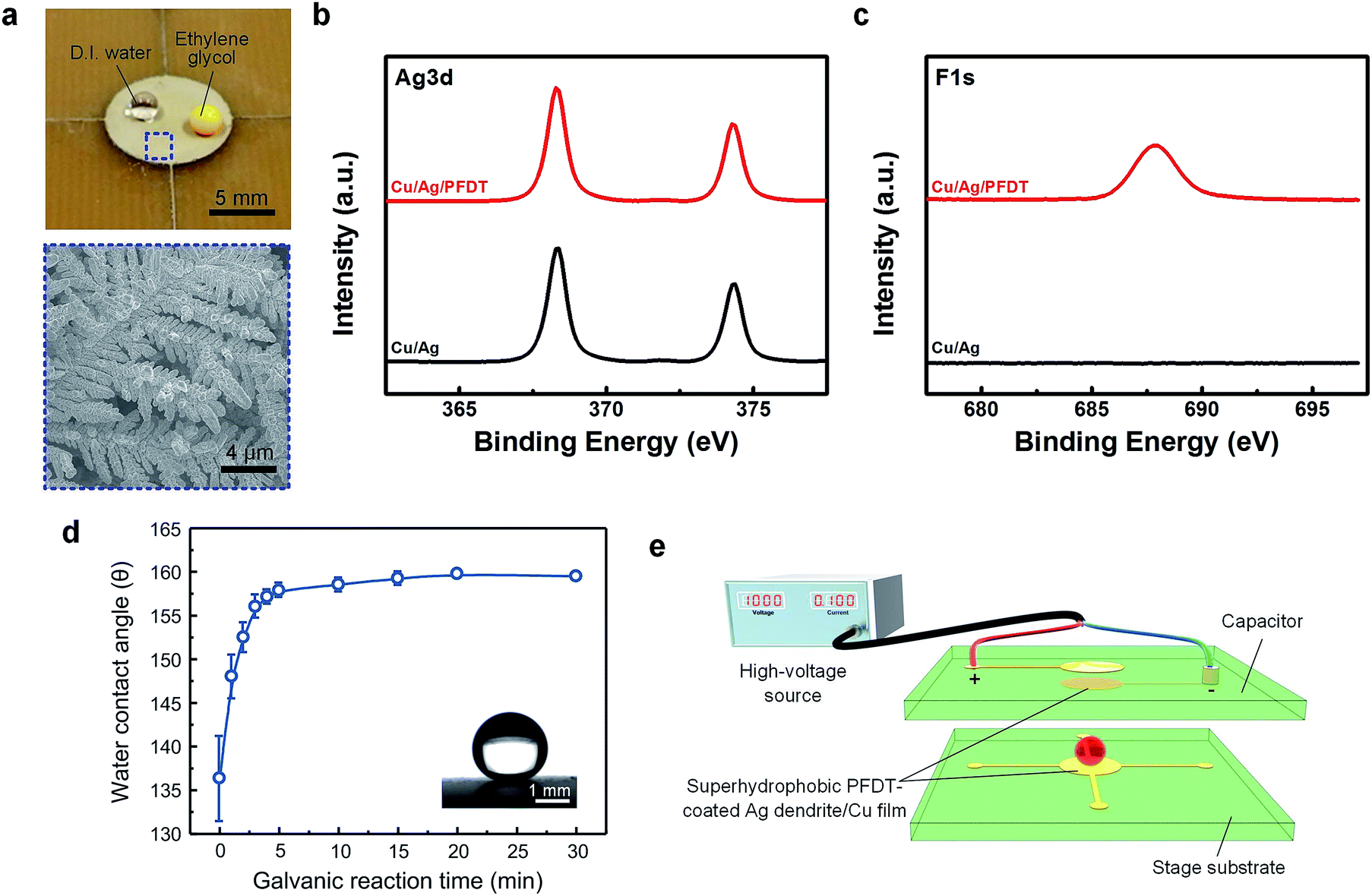 | ||
| Fig. 1 (a) Photograph image showing the high CAs of water and EG on the superhydrophobic electrode. (Bottom blue box: SEM image of the PFDT-coated Ag dendrite/Cu film at tg = 30 min.) XPS results of (b) Ag 3d and (c) F 1s for Ag dendrite-grown Cu and PFDT-coated Ag dendrite/Cu film. (d) CAs of ∼5 μL water droplets on the surface of PFDT-coated Ag dendrite/Cu films of the stage substrate as a function of tg. (The inset shows the optical image of a water droplet on the PFDT-coated Ag dendrite/Cu film at tg = 30 min.) (e) Schematic illustration of experimental set up for the droplet bouncing actuating system. | ||
Bouncing actuator setup
The capacitive electrode was placed above the stage electrode with spacing distances of 2, 2.5, and 3 mm. The circularly patterned Cu films of the capacitive and stage electrodes were vertically aligned. To apply electrostatic field across the top and bottom of capacitive electrode, wires were soldered to the circular shaped Cu films for both sides by Via and connected to a high voltage power supply (PS325, Stanford Research Systems). The top side of capacitive electrode was connected to electrical ground and the bottom side of capacitive electrode was applied with negative voltage ranging from 0 to −1.7 kVDC with 0.001% regulation. The stage electrode was connected to the ground conductor of a 200 μm-thick Cu foil with a dimension of 20 × 20 cm2 through the bottom side, which limited the available charge. This configuration allowed the injection of free electrons to a droplet on the stage electrode and prevented a direct discharge between the bottom side of capacitive electrode and the stage electrode, which might result in an electric spark during the rapidly-bouncing motion of droplet.Characterization
The surface morphology of the Ag dendrite-covered Cu film was examined using a JEOL JSM-7001F field emission scanning electron microscope (FE-SEM). Water contact angles (CAs) were observed by a dynamic image capture camera (DSC-T30, SONY Co., Ltd.), whereas the droplet images were captured using a high-speed video camera (Kodak Motion Corder Analyzer PS-220, SR-Ultra-C) operating at a rate of 2000 frames per s and equipped with a 12 mm video lens (Cosmicar/Pentax TV-lens, 12 mm, 1![[thin space (1/6-em)]](https://www.rsc.org/images/entities/char_2009.gif) :1:2). XPS spectra were obtained using a K-alpha instrument (Thermo Scientific) equipped with a monochromated Al Kα X-ray source (1486.6 eV). The X-ray power was 12 kV and 3 mA with a spot size of 400 μm diameter and pass energy of 40 eV. The numerical results were simulated using a commercial numerical solver (COMSOL Multiphysics 5.0). The current during droplet bouncing was measured using a Keithley 2400 SourceMeter (Keithley Instruments Inc., Cleveland, OH, USA).
:1:2). XPS spectra were obtained using a K-alpha instrument (Thermo Scientific) equipped with a monochromated Al Kα X-ray source (1486.6 eV). The X-ray power was 12 kV and 3 mA with a spot size of 400 μm diameter and pass energy of 40 eV. The numerical results were simulated using a commercial numerical solver (COMSOL Multiphysics 5.0). The current during droplet bouncing was measured using a Keithley 2400 SourceMeter (Keithley Instruments Inc., Cleveland, OH, USA).
Results and discussions
To obtain a superhydrophobic surface for the rapidly-bouncing droplet actuator, PFDT-coated Ag dendrite/Cu films were fabricated by sequential processes of electroless galvanic replacement reaction and PFDT chemical coating.26 The dendritic structure is advantageous due to the microscale overhang-like structures, and hierarchical structures with a large number of nanoscale air cavities.27 Detailed explanations of Ag dendrite formation on the surface of Cu film by electroless galvanic replacement were presented in our previous studies.21,27 Briefly, when a Cu film was immersed in an AgNO3 aqueous solution, micro- and nano-scale metal particles of Ag are selectively formed on the Cu film. Since the ionization tendency of Cu is higher than that of Ag, Ag ions are reduced to Ag atoms on the Cu film while Cu atoms are converted into Cu ions. The electroless galvanic replacement reaction can be expressed as follows:| Cu + 2Ag+ → Cu2+ + 2Ag | (1) |
As the dipping time of AgNO3 aqueous solution increases, Ag particles aggregate together, and leaf-structured Ag dendrites form only on the Cu films. Since the branched Ag dendrites, which are composed of micro- and nano-scale metal particles, have hierarchical roughness, Cassie-Baxter surfaces were formed.28
Along with the chemical coating of PFDT on the Ag dendrite/Cu film for a low surface energy, superhydrophobic electrodes were successfully obtained. Fig. 1a is a photograph of ∼5 μL water and ethylene glycol droplets with CAs > 150° on the superhydrophobic electrode and a SEM image of the branched Ag dendrites on the Cu film with a hierarchical roughness where the galvanic reaction time (tg) is 30 minutes. Fig. 1b and c shows the XPS measurement results of the Ag dendrite-grown Cu and PFDT-coated Ag dendrite/Cu film. Ag was observed after Ag dendrite growth and F was observed after coating PFDT. Neither peaks were observed for the bare Cu film. Fig. 1d shows the CAs of water droplets on the surface of the superhydrophobic electrode as a function of tg. The water CA of PFDT-coated Cu film was initially 136.4° (tg = 0) and drastically increased with tg. When tg > 5 minute, the CA became saturated at an angle of ∼160°, meaning that the wetting property was converted into the superhydrophobic state. The inset of Fig. 1d is an optical image of a static water droplet on the flat surface of the superhydrophobic electrode at tg = 30 minute which results in a high CA of 159.5°, allowing a complete rebound of single droplet. In our study, we used tg = 30 minute for the superhydrophobic electrode for the electrostatic force-driven droplet actuator.
The superhydrophobic capacitive and stage electrodes were set up to examine the droplet bouncing actuator with electrostatic force as depicted in Fig. 1e. The capacitive electrode was located above the stage electrode at a distance of 2, 2.5 or 3 mm and the electrodes were well aligned to apply a uniform electrostatic field. The top and bottom of the capacitive electrode were respectively connected to the cathode and anode of a high-voltage power source, which was negatively biased up to 1.7 kVDC. Below the voltage of the bouncing threshold, the shape and motion of the droplet were not changed. However, when the applied voltage was sufficiently high, the electrostatic force applied to the water droplet became larger than the gravitational force, resulting in the D.I. water droplet bouncing as shown in Video S1.† The adhesion force between the droplet and the upper/bottom surfaces during the bouncing motion can be neglected since both the stage electrode and the bottom of capacitive electrode have Cassie-Baxter superhydrophobic surfaces. When a hydrophobic electrode was used, the droplet bouncing frequency was very slow (0.17 Hz) as shown in video S2.† The droplet was slowly elongated before detaching from the electrode, which is due to the larger adhesion to the electrodes.
When the applied voltage was decreased to a certain extent after the start of bouncing motion, the bouncing speed of the water droplet was also decreased, but the water droplet still maintained its bouncing motion despite the applied voltage being lower than the bouncing threshold. This can be explained by the energy dissipation and surface energy conservation of the droplet.29 At the moment of the collision of the droplet with the solid substrate, the kinetic energy of the droplet is converted into the surface and dissipation energies of the droplet. The surface energy of the droplet was stored in the form of the surface deformation energy of the droplet. The converted surface energy of the droplet can then be converted into the kinetic energy of the droplet due to the surface tension inducing the bouncing motion of the droplet from the substrate. As the water droplet is much smaller than the capillary length of water (∼2.7 mm), the gravitational-potential energy can be neglected.30 In our system, owing to the superhydrophobic electrodes, the kinetic energy dissipation of the droplet would be small and the converted kinetic energy of the droplet would be maximized.29 Therefore, when the sum of the electrostatic and converted kinetic forces of the droplet is larger than the gravitational force, the droplet can keep its bouncing motion even at the applied voltage lower than the original bouncing threshold. When the applied voltage was continuously decreased, the bouncing motion of the water droplet finally stopped since the sum of the electrostatic and converted kinetic forces was smaller than the gravitational force of the droplet.
To observe the bouncing motion of droplets in detail, the bouncing motions of droplets were investigated using a high-speed video camera. Fig. 2a and b and Video S3† represents sequential photographs (0.5 ms per frame) of the bouncing motion of a ∼1 μL D.I. water droplet between the superhydrophobic electrodes. Fig. 2a provides captured images in the middle of the bouncing motion of the water droplet when the applied voltage and the distance between superhydrophobic electrodes were 0.7 kV and 2.5 mm, respectively. The returning time (period) of the bouncing water droplet was 8 ms (bouncing frequency = 125 Hz). As the water droplet approached either side of the superhydrophobic electrodes, its shape was deformed in two ways. When the water droplet approached the surface of the superhydrophobic electrodes, the adjacent surface of the water droplet was slightly elongated toward the electrode, as shown in the droplet at the time of 2.5 ms in Fig. 2a. This could be attributed to the fact that the electrostatic field generated between the superhydrophobic electrode and the surface of the droplet was increased due to the reduced distance between them.31 Thus, charges were concentrated on the surface of the droplet adjacent to the superhydrophobic electrode and consequently the elongated shape was formed due to the high electrostatic force. Another deformation occurred at the moment of collision between the droplet and the superhydrophobic electrode. The droplet was significantly flattened by the inertial force during the collision of bouncing liquid droplet to the rigid superhydrophobic electrodes with high speed.
 | ||
| Fig. 2 Sequential photographs representing the motion and deformation of a ∼1 μL water droplet during bouncing movement between the superhydrophobic capacitive electrode and stage electrode at an applied voltage of (a) 0.7 kV and (b) 1 kV using a high-speed camera. A droplet of PEDOT:PSS solution was also measured during bouncing motion at an applied voltage of (c) 1 kV and (d) 1.2 kV. | ||
To observe the effect of the applied voltage, we investigated the bouncing motion of the water droplet with an increased bias voltage of 1 kV as shown in Fig. 2b. The period of the bouncing motion was measured to be 1.75 ms (bouncing frequency = 0.57 kHz), which was about 4.5 times shorter than that of under 0.7 kV. The bouncing frequency of the water droplet was proportional to the electrostatic force and the extent of droplet deformation was also enhanced corresponding to the increased inertial force. If the bouncing velocity of the droplet were to be too high, a transition from Cassie state to Wenzel state could have occurred during the collision due to the damaged surface and thus the droplet could stick to the electrode and stop the bouncing motion. Nevertheless, this phenomenon was not observed in our actuator until the droplet was fully evaporated, indicating that the fabricated superhydrophobic electrodes have high stability under mechanical stress.
When a droplet bounces on a non-wetting surface, the characteristics are affected by the droplet size, speed and Weber number.32 The Weber number is a dimensionless value which compares the kinetic and surface energies of the droplet which is as follows:32
| W = ρV2R/γ | (2) |
Fig. 2c shows the sequential images of a ∼1 μL droplet of PEDOT:PSS solution with an applied voltage of 1 kV in order to investigate the effects of the droplet's properties on the bouncing motion. The distance between the electrodes was maintained to be 2.5 mm. The measured bouncing period of the PEDOT:PSS droplet was 3.5 ms (bouncing frequency = 0.28 kHz), which was longer than that of the water droplet with the same bias voltage. When the applied voltage was increased to 1.2 kV, the bouncing period was also decreased to 1.4 ms (bouncing frequency = 0.71 kHz) with the help of the increased electrostatic force (Fig. 2d).
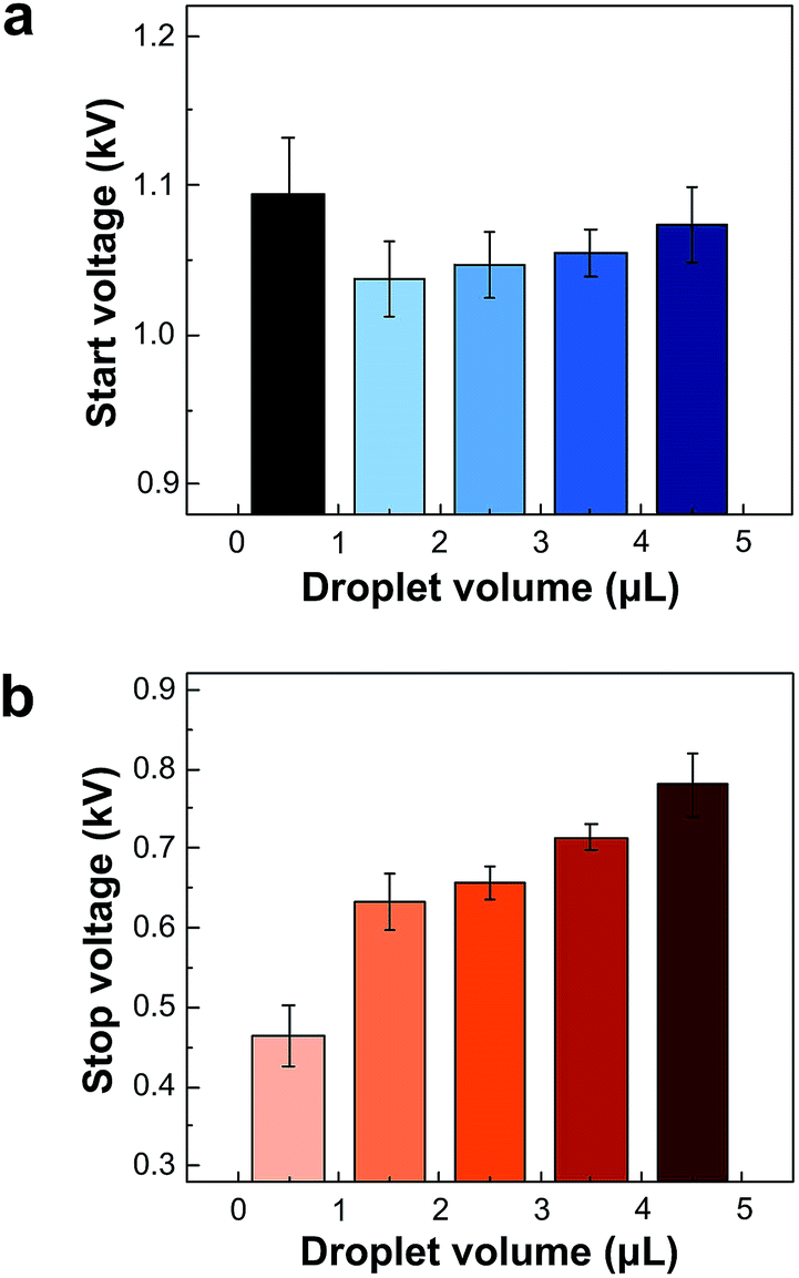
When an ideal conducting solid sphere contacts with an electrode under electric field, the amount of induced charge on the surface of the droplet by the electrode (Q) is given as follows:33
 | (3) |
| Distance (mm) | Bouncing start voltages (kV) | |
|---|---|---|
| Water | PEDOT:PSS | |
| 2.5 | 1.049 | 0.992 |
| 3.0 | 1.357 | 1.298 |
| 3.5 | 1.620 | 1.572 |
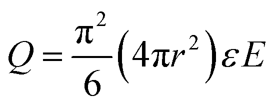
To investigate the dependency on the droplet volume, the start and stop voltages of the bouncing motion were analyzed. Fig. 3a represents the average start voltages of the bouncing motion of water droplet according to the droplet volume. When the volume was above 1 μL, it was proportional to the droplet volume. To start the droplet bouncing, the electrostatic force exerted to the droplet should be higher than the gravitational force of the droplet. The electrostatic force was determined by the induced surface charge of the droplet under constant electrostatic field, which was proportional to the surface area of droplet as shown in eqn (3). Meanwhile, the gravitational force (Fg = ρVg, where ρ is the density of the droplet, V is the volume of the droplet, and g is the gravitational acceleration) was proportional to the droplet volume, showing that the dimension of the droplet largely affects the gravitational force than the electrostatic force.37 Thus, when the dimension of the droplet was increased, higher bias voltages were required to overcome the increased gravitational force for the start of bouncing motion.
 | ||
| Fig. 3 Changes of (a) start and (b) stop voltages of water droplet bouncing motion depending on the droplet volume. | ||
On the contrary, when the droplet volume was in the nano-liter range (<1 μL), the start voltage of bouncing motion was increased to about 1.1 kV despite the volume decrease. Due to the reduction-nucleation-growth process of the electroless galvanic replacement reaction, leaf-textured Ag dendrites with micro-scaled stem and branches were covered with Ag nanoparticles on the Cu films (Fig. 1a). Especially, a large number of voids under the Ag leaf-textured dendrites were easily observed.24 When the micro-liter water droplet was dropped on the superhydrophobic PFDT-coated Ag dendrite/Cu films with hierarchical roughness, air pockets between the superhydrophobic surface and the droplet are assumed to be trapped under the droplet, leading to the formation of a Cassie-state.38 However, when the size of the water droplet decreased to nano-liter volume, it was hard to retain the Cassie state and the wetting mode was changed to a Wenzel state.39 Since the liquid entirely fills the grooves of the rough surface in the Wenzel state, the adhesion force between the surface and the droplet is higher than that of the Cassie state.40 Therefore, the sliding angle of the nano-liter sized water droplet increased to approximately 10°, as shown in Fig. S1,† which was higher than that of micro-liter sized water droplet (almost zero). Therefore, the required electrostatic force to overcome the sum of the increased adhesion and gravitational forces for bouncing motion increased and the start voltage of the nano-liter sized droplet bouncing was higher than that of micro-liter sized one. In the case of the stop voltage of bouncing motion, the tendency was quite different from the start voltage. As shown in Fig. 3b, regardless of the nano- or micro-liter droplets, the stop voltage was constantly increased as the volume increase of water droplets. It would be attributed to the fact that the air pockets could be retained due to the high-speed bouncing motion. Since the droplet bouncing happened within very short period, there is no time to wet the groove of rough surface and wipe out air pockets.
The mechanism of droplet bouncing motion under electrostatic field can be explained by the repeated charging/discharging process between the droplet and the electrodes.34 Fig. 4a illustrates the bouncing mechanism of an aqueous droplet on a superhydrophobic electrode according to the position of the droplet. First, when a negative bias was applied to the upper capacitive electrode, negative and positive charges are accumulated to the bottom and top of the capacitive electrode, respectively. Due to the bottom's negative charge of the capacitive electrode, a positive charge was induced to the stage electrode. Since a water droplet was placed on the stage electrode which is positively charged, the surface charge redistribution of the liquid droplet induces the charging process and the amount of charge can be estimated by using eqn (3). When the electrostatic force originating from the surface charge overcame the gravitational force by increasing the applied voltage, the droplet moved toward the bottom side of the capacitive electrode. Assuming that the amount of charge at the start of bouncing is +Q, once the droplet reaches the negatively-charged bottom of capacitive electrode, it continues to increase its negative charges, which results in the excess of negative charge (−Q). Then, the droplet comes back to the positively-charged stage electrode by the oppositely-conversed electrostatic and gravitational forces. The droplet is charged again at the stage electrode and this charging/discharging process is repetitively occurred as long as the electric field is maintained.
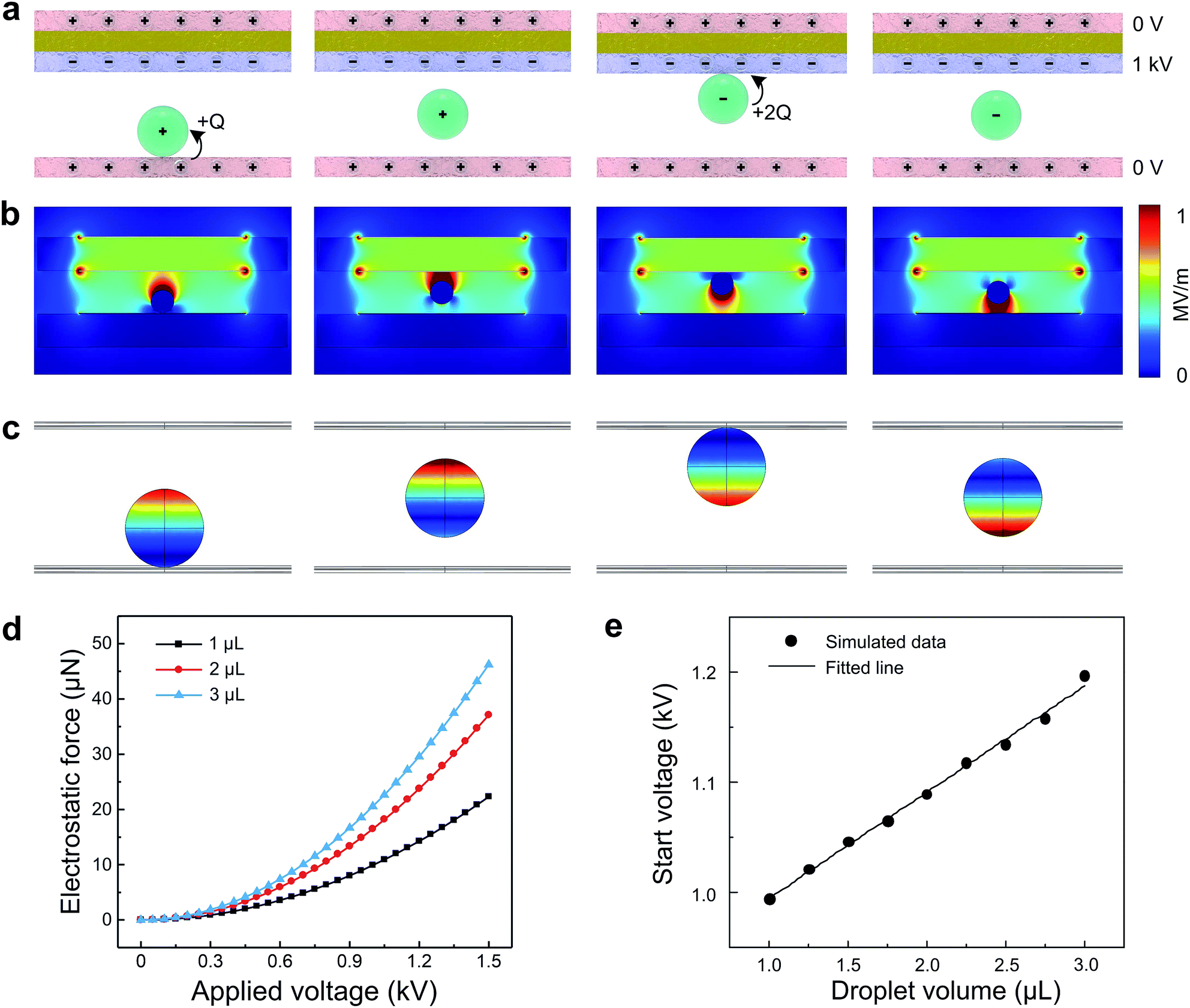 | ||
| Fig. 4 (a) Pictorial descriptions on the mechanism of droplet bouncing motion by the repetitive charging/discharging process. Electrostatic field distributions of (b) the droplet actuating system and (c) the surface of water droplets at different locations between the capacitive electrode and stage electrode using a simulation tool. (d) Electrostatic forces of 1, 2, and 3 μL water droplets depending on the applied voltage obtained from the simulation model. (e) Simulated data (symbol) of the start voltages of water droplets and the fitted line of the simulated data by varying the droplet volumes ranged from 1.0 to 3.0 μL. | ||
We also examined the dynamics of electrostatic field distributions of the rapidly-bounced droplet actuator by using a commercial numerical solver, COMSOL Multiphysics 5.0, based on the electrostatic module as shown in Fig. 4b. The simulation model of the rapidly-bouncing droplet actuator was identically structured as seen in Fig. 1e. In this simulation, the top side of the capacitive electrode and the stage electrode were electrically grounded and the bottom side of the capacitive electrode was biased with a −1 kVDC. The bouncing distance between electrodes was set to be 2.5 mm and the water droplet was assumed to be a 0.7 mm-radius sphere. The physical parameters in the simulation are represented in Table 2. Fig. 4c shows the sequential electrostatic field distributions on the surface of the water droplet when it vertically bounced. When the water droplet was placed on the surface of the stage electrode and moved upward, the electrostatic field on the surface of the water droplet was concentrated toward the direction of the negatively-biased electrode. When the water droplet was located on the surface of the bottom side of capacitive electrode and moved downward, the electrostatic field on the surface of the droplet was concentrated toward the direction of the stage electrode.
| Conductivity of Cu | 5.998 × 10⁷ S m−1 |
| Relative dielectric constant of liquid water | 78 |
| Relative dielectric constant of glass | 4.2 |
| Relative dielectric constant of air | 1 |
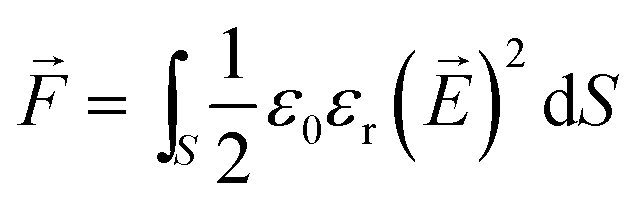
When the liquid droplet is placed under an electrostatic field, the electrostatic force exerted on the droplet (![[F with combining right harpoon above (vector)]](https://www.rsc.org/images/entities/i_char_0046_20d1.gif) ) can be calculated by the Maxwell stress tensor method as follows:41
) can be calculated by the Maxwell stress tensor method as follows:41
 | (4) |
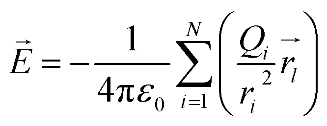
![[E with combining right harpoon above (vector)]](https://www.rsc.org/images/entities/i_char_0045_20d1.gif) is the electrostatic field. Furthermore, is affected by Coulomb's law and the superposition principles as shown by the following equation.21
is the electrostatic field. Furthermore, is affected by Coulomb's law and the superposition principles as shown by the following equation.21
 | (5) |
 is the corresponding unit vector of ri, which is the position of charge Qi. The boundary conditions used in this simulation are as follows:
|
= −∇ϕ, where ϕ is the electrical potential
| (6) |
From eqn (3)–(5), we calculated the electrostatic forces exerted on 1, 2, and 3 μL water droplets by increasing the applied voltage using the simulation model (Fig. 4d). As the applied voltage and the droplet volume increased, the electrostatic forces also increased and showed non-linear characteristics as expected. In order to investigate the effect of droplet volume on bouncing motion, we estimated the start voltage of bouncing motion of the water droplet by varying the droplet volume as shown in Fig. 4e using the COMSOL. The estimated electrostatic forces were not exactly the same with those of our experimental results in Fig. 3a. Even if the overall electrostatic force is smaller than the gravitational force, the electrostatic force may be larger in some local regions, leading to local deformation of the droplet. Also, water is not an ideal conducting solid. Nevertheless, the start voltage obtained by the simulation model almost linearly increased depending on the droplet volume, indicating a similar tendency to our measured data.
In order to confirm the repetitive charging/discharging process during droplet bouncing, we measured the electric current signal of the droplet during bouncing motion by connecting a current source meter to the stage electrode. Fig. 5 represents the current signal of a ∼1 μL water droplet during bouncing motion over 50 seconds for applied voltages from 1.3 to 0.7 kVDC with a 0.1 kV interval. The droplet started bouncing at the applied voltage of 1.3 kV and approximately 6 nA current was measured with a 1 nA current fluctuation. When the applied voltage was gradually decreased with a step size of 0.1 kV, the current also decreased with a current step of about 0.8 nA. Then, the droplet eventually stopped bouncing at 0.7 kV and no current was measured. The current tendency of PEDOT:PSS solution depending on the applied voltage was also similar to that of the water droplet (Fig. S2†). Interestingly, the measured current during the bouncing motion of the water droplet shows a continuous waveform, not a pulse-type. By the bouncing mechanism of droplet shown in Fig. 4a, the current characteristic should be a pulse-type signal, and not a continuous current signal, as shown in Fig. 5.34 This can be attributed to the fact that the acquisition time of the current source meter (0.082 sec) was much longer than the time of droplet bouncing once (e.g., 0.00175 sec at 1 kV using the water droplet). Furthermore, when the applied voltage was 1.3 kV, the obtained current was not constant, but gradually decreased. This can be explained by the evaporation of the droplet during bouncing motion with high-speed. To confirm the evaporation effect of the bouncing droplet, the current change of water droplet was investigated, as shown in Fig. S3.† The current gradually decreased over time and stopped when the water droplet was completely evaporated during the bouncing motion.
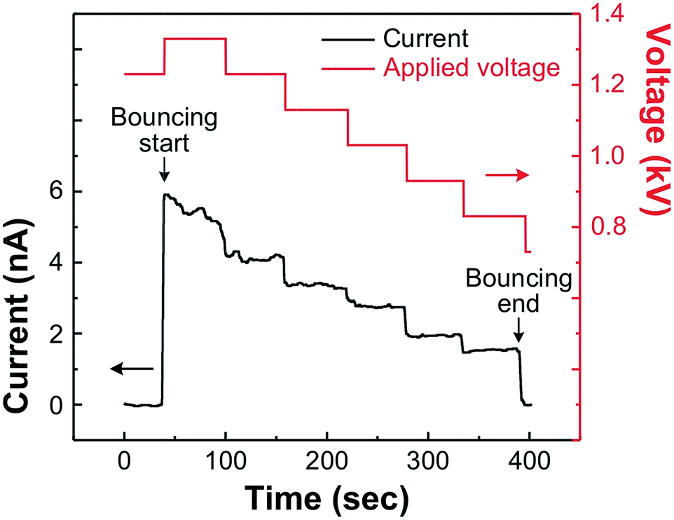 | ||
| Fig. 5 The current changes of a ∼1 μL water droplet during bouncing motion on the superhydrophobic electrodes under 50 seconds each of the applied voltage at 1.3 kV to 0.7 kV with a 0.1 kV interval. | ||
Conclusions
In summary, we have demonstrated a rapidly-bouncing droplet actuator using superhydrophobic PFDT-coated Ag dendrite/Cu films, which were easily obtained by galvanic displacement. When the electrostatic force was higher than the gravitational force by increasing the applied voltage, various droplets including water and PEDOT:PSS solution were successfully bounced between the circular-patterned superhydrophobic stage electrode and capacitive electrode. The movement and deformation of droplets during the high-speed bouncing motion were examined using a high-speed video camera (0.5 ms per frame). Furthermore, the effects of the droplet volume, types of liquid materials, and applied voltage on the bouncing motion were experimentally investigated. Due to the repetitive charging/discharging process and the use of superhydrophobic surfaces, without any bias switching, the droplets continuously showed ultrafast bouncing motion (0.57 kHz for water and 0.71 kHz for PEDOT:PSS solution) under the electrostatic field. To verify this process, the current signals of the droplets were measured during bouncing motion and a few nA current was continuously measured at the current source meter. We expect that this droplet bouncing actuator with high-speed, contamination-free and facile method can be applicable to the advanced functional open-channel lab-on-a-chip technology such as biomedical diagnosis and micro reactors.Acknowledgements
This work was supported by the Priority Research Centers Program (Grant No. 2009–0093823) through the National Research Foundation (NRF) of Korea funded by the Ministry of Education, Science and Technology (MEST) and Mid-career Researcher Program through NRF grant funded by the MEST (2014R1A2A2A09053061).Notes and references
- J. B. Chae, I. U. Shin, K. Rhee and S. K. Chung, 2013 Transducers & Eurosensors XXVII: The 17th International Conference on Solid-State Sensors, Actuators and Microsystems (TRANSDUCERS & EUROSENSORS XXVII), 16-20 June 2013, pp. 1286–1289 Search PubMed.
- R. A. Hayes and B. J. Feenstra, Nature, 2003, 425, 383–385 CrossRef CAS PubMed.
- H. Song, J. D. Tice and R. F. Ismagilov, Angew. Chem., Int. Ed., 2003, 42, 768–772 CrossRef CAS PubMed.
- A. R. Parker and C. R. Lawrence, Nature, 2001, 414, 33–34 CrossRef CAS PubMed.
- B. Berge and J. Peseux, Eur. Phys. J. E, 2000, 3, 159–163 CrossRef CAS.
- S. Santesson, M. Andersson, E. Degerman, T. Johansson, J. Nilsson and S. Nilsson, Anal. Chem., 2000, 72, 3412–3418 CrossRef CAS PubMed.
- C. Li, R. Guo, X. Jiang, S. Hu, L. Li, X. Cao, H. Yang, Y. Song, Y. Ma and L. Jiang, Adv. Mater., 2009, 21, 4254–4258 CrossRef CAS.
- J. Seo, S. Lee, H. Han, H. B. Jung, J. Hong, G. Song, S. M. Cho, C. Park, W. Lee and T. Lee, Adv. Mater., 2013, 25, 4139–4144 CrossRef CAS PubMed.
- J. Seo, S.-K. Lee, J. Lee, J. Seung Lee, H. Kwon, S.-W. Cho, J.-H. Ahn and T. Lee, Sci. Rep., 2015, 5, 12326 CrossRef PubMed.
- F. Mugele and J.-C. Baret, J. Phys.: Condens. Matter, 2005, 17, R705 CrossRef CAS.
- J. Voldman, Annu. Rev. Biomed. Eng., 2006, 8, 425–454 CrossRef CAS PubMed.
- H. Zhou and S. Yao, Lab Chip, 2013, 13, 962–969 RSC.
- A. Kumar, H.-S. Chuang and S. T. Wereley, Langmuir, 2010, 26, 7656–7660 CrossRef CAS PubMed.
- S. Zeng, C.-H. Chen, J. C. Mikkelsen Jr and J. G. Santiago, Sens. Actuators, B, 2001, 79, 107–114 CrossRef CAS.
- T. Wu, Y. Suzuki and N. Kasagi, J. Micromech. Microeng., 2010, 20, 085043 CrossRef.
- T. P. Hunt, D. Issadore and R. M. Westervelt, Lab Chip, 2008, 8, 81–87 RSC.
- M. G. Pollack, R. B. Fair and A. D. Shenderov, Appl. Phys. Lett., 2000, 77, 1725–1726 CrossRef CAS.
- J. Hong, Y. K. Kim, D.-J. Won, J. Kim and S. J. Lee, Sci. Rep., 2015, 5, 10685 CrossRef CAS PubMed.
- T. Wu and Y. Suzuki, Lab Chip, 2011, 11, 3121–3129 RSC.
- S. Jun Lee, S. Lee and K. Hyoung Kang, Appl. Phys. Lett., 2012, 100, 081604 CrossRef.
- S. Lee, S. Lee, D. Kim, J. Seo, C. Mahata, H. Hwang, H. Algadi, S. Al-Sayari, Y. Chae and T. Lee, RSC Adv., 2015, 5, 5754–5761 RSC.
- D. J. Im, J. Noh, D. Moon and I. S. Kang, Anal. Chem., 2011, 83, 5168–5174 CrossRef CAS PubMed.
- S. Park, C. Pan, T.-H. Wu, C. Kloss, S. Kalim, C. E. Callahan, M. Teitell and E. P. Y. Chiou, Appl. Phys. Lett., 2008, 92, 151101 CrossRef PubMed.
- T. Taniguchi, T. Torii and T. Higuchi, Lab Chip, 2002, 2, 19–23 RSC.
- M. Washizu, IEEE Trans. Ind. Appl., 1998, 34, 732–737 CrossRef CAS.
- I. A. Larmour, S. E. J. Bell and G. C. Saunders, Angew. Chem., Int. Ed., 2007, 119, 1740–1742 CrossRef.
- D. Kim, J. Seo, S. Shin, S. Lee, K. Lee, H. Cho, W. Shim, H.-B.-R. Lee and T. Lee, Chem. Mater., 2015, 27, 4964–4971 CrossRef CAS.
- A. B. D. Cassie and S. Baxter, Trans. Faraday Soc., 1944, 40, 546–551 RSC.
- D. J. Lee, H. M. Kim, Y. S. Song and J. R. Youn, ACS Nano, 2012, 6, 7656–7664 CrossRef CAS PubMed.
- Z. Wang, F.-C. Wang and Y.-P. Zhao, Proc. R. Soc. A, 2012, 468, 2485–2495 CrossRef.
- Y.-M. Jung, H.-C. Oh and I. S. Kang, J. Colloid Interface Sci., 2008, 322, 617–623 CrossRef CAS PubMed.
- D. Richard, C. Clanet and D. Quere, Nature, 2002, 417, 811 CrossRef CAS PubMed.
- A. Khayari and A. T. Perez, IEEE Trans. Dielectr. Electr. Insul., 2002, 9, 589–595 CrossRef.
- D. J. Im, M. M. Ahn, B. S. Yoo, D. Moon, D. W. Lee and I. S. Kang, Langmuir, 2012, 28, 11656–11661 CrossRef CAS PubMed.
- L. Korson, W. Drost-Hansen and F. J. Millero, J. Phys. Chem., 1969, 73, 34–39 CrossRef CAS.
- T. Mao, D. C. S. Kuhn and H. Tran, AIChE J., 1997, 43, 2169–2179 CrossRef CAS.
- K. Takeda, A. Nakajima, K. Hashimoto and T. Watanabe, Surf. Sci., 2002, 519, L589–L592 CrossRef CAS.
- Y. Lai, X. Gao, H. Zhuang, J. Huang, C. Lin and L. Jiang, Adv. Mater., 2009, 21, 3799–3803 CrossRef CAS.
- T. Furuta, T. Isobe, M. Sakai, S. Matsushita and A. Nakajima, Appl. Surf. Sci., 2012, 258, 2378–2383 CrossRef CAS.
- M. Liu and L. Jiang, Adv. Funct. Mater., 2010, 20, 3753–3764 CrossRef CAS.
- N. A. Patankar, Langmuir, 2004, 20, 8209–8213 CrossRef CAS PubMed.
Footnotes |
| † Electronic supplementary information (ESI) available. See DOI: 10.1039/c6ra12092j |
| ‡ These authors equally contributed to this work. |
| This journal is © The Royal Society of Chemistry 2016 |