Huiyuan Liuabc,
Yujiang Song*b,
Shushuang Lia,
Jia Lib,
Yuan Liuad,
Ying-Bing Jiange and
Xinwen Guob
aDalian National Laboratories for Clean Energy, Dalian Institute of Chemical Physics, Chinese Academy of Sciences, Dalian, Liaoning 116023, China
bState Key Laboratory of Fine Chemicals, School of Chemical Engineering, Dalian University of Technology, Dalian, Liaoning 116024, China. E-mail: yjsong@dlut.edu.cn
cUniversity of Chinese Academy of Sciences, Beijing 100039, China
dChongqing Institute of Green and Intelligent Technology (CIGIT), Chinese Academy of Sciences, Chongqing 400714, China
eDepartment of Earth and Planetary Sciences, The University of New Mexico, Albuquerque, New Mexico 87131, USA
First published on 4th July 2016
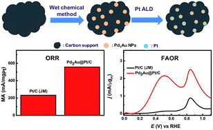
We report the synthesis of Pd3Au@Pt/C by atomic layer deposition (ALD) combined with a wet chemical method. Initially, nearly uniform Pd3Au nanoparticles (NPs) (∼4.7 nm) supported on carbon with a loading of ∼20 wt% were prepared by reducing metal complexes confined in reverse micelles adsorbed on carbon. Next, a Pt thin layer (less than 1 nm) was selectively deposited on purified Pd3Au particles instead of on carbon by regioselective ALD that likely arises from the coverage of nucleation sites on carbon by surfactant molecules in conjunction with catalytic decomposition of the Pt precursor on Pd3Au. The resulting core–shell structured material was subject to TEM, HAADF-STEM/EDX, XRD, XPS and electrochemical measurements. Interestingly, Pd3Au@Pt/C demonstrates a significantly improved electrocatalytic activity toward both formic acid oxidation reaction (FAOR) and oxygen reduction reaction (ORR) compared with Pd3Au/C and state-of-the art Pt/C. This study opens up a unique avenue for the synthesis core/shell structured materials with potential applications in catalysis, electrocatalysis, and so on.
Typical wet chemical synthesis of core/shell structured NPs includes seeding method,17–21 Cu underpotential deposition (Cu-UPD),8,10–12 and dealloying.15,22,23 As a gas phase technique, ALD is capable of conformably coating a substrate at the atomic level relying on self-limiting surface reactions.24,25 Recently, ALD has been applied to the synthesis of core/shell structured metallic NPs supported on oxides.26–30 However, the core/shell structured NPs supported on carbon by ALD remains a challenge possibly because of the lack of active nucleation sites on carbon, leading to insufficient chemisorption of metal precursors and thus severe particle aggregation.31,32 Accordingly, pre-formation of uniform Pd3Au cores on carbon becomes critical for the synthesis of Pd3Au@Pt/C NPs.
In this study, we present a new synthetic approach for the creation of core/shell structured Pd3Au@Pt/C by ALD combined with a wet chemical method. The nearly uniform Pd3Au core on carbon was firstly prepared by reducing metallic complexes confined in reversed micelles and then Pt-shell was selectively deposited on Pd3Au by ALD likely due to the coverage of nucleation sites on carbon by surfactant molecules in conjunction with catalytic decomposition of Pt precursor on Pd3Au. The resulting core–shell structured electrocatalyst demonstrates significantly improved activity toward FAOR and ORR compared with Pd3Au/C and state-of-the art Pt/C. This study provides a unique route to prepare core/shell structured NPs with potential applications in electrocatalysis, catalysis, and so on.
Carbon was also treated by above procedure without the addition of metal complexes and labelled as C-PT. VXC-72 carbon black (about 60.0 mg) was dispersed in 10 mL of chloroform containing 40 mM CTAB under sonication for at least 5 min, forming reversed micelles absorbed on carbon. Next, 90 mL of deionized water was added in and then 10 mL of 300 mM NaBH4 was added under stirring at 1600 rpm. Finally, we purified the carbon simply by washing with copious amount of hot water.
For comparison, platinum was also deposited on bare VXC-72 carbon black with and without phase transfer processing by using the same Pt ALD process as that employed for Pd3Au@Pt/C. These samples were labeled as Pt/C (ALD) and Pt/C-PT (ALD), respectively. Additionally, in the absence of Pt precursor Pd3Au/C was also treated by the same ALD process to examine the heating effect of ALD process. This sample was indexed as Pd3Au/C (heat).
UV-visible spectra were obtained with a spectrophotometer (Analytic Jena, Specord S600) and a 0.2 cm path length quartz cell.
Certain amount of water, ethanol, Nafion solution (5 wt% Dupont) (v:
v
:
v = 1
:
9
:
0.06) and electrocatalyst were mixed and sonicated in a water bath for 2 min, obtaining a catalyst ink (1 mg mL−1). The working electrodes were glassy carbon rotating disk electrodes (RDE), 5 mm in diameter (0.19625 cm2). Glassy carbon was polished with 0.05 μm Bio-Analytical Systems (BAS) alumina paste. 10 μL of catalyst ink was transferred onto RDE and then evaporated the solvent in the air.
CV curves were recorded at 25 ± 0.5 °C in N2-saturated 0.1 M HClO4 aq. with a sweep rate of 50 mV s−1. CV measurements were performed for multiple cycles until obtaining a stable curve. ORR polarization curve of the catalysts was recorded at 25 ± 0.5 °C in O2-saturated 0.1 M HClO4 aq. with a positive sweep rate of 10 mV s−1 at 1600 rpm. Current densities in the ORR polarization curves were normalized to the geometric area of the glassy carbon RDE. The kinetic current was calculated based on the Koutecky–Levich equation:
The electrocatalytic activity towards FAOR was evaluated using LSV in a N2-saturated aq. containing CHOOH (0.5 M) and H2SO4 (0.5 M) at 25 ± 0.5 °C. The potential was swept between 0 and 1.1 V (vs. RHE) with a scan rate of 10 mV s−1 at 900 rpm. The CA curves for Pd3Au@Pt/C and commercial Pt/C (JM) were also recorded in N2-saturated aqueous solution containing 0.5 M formic acid (FA) and 0.5 M H2SO4 with a rotation rate of 900 rpm at 0.5 V (vs. RHE) for 1 h at 25 ± 0.5 °C.
TEM images (Fig. 1a) and particle size distribution histogram (Fig. S2a†) reveals that the average size of as-prepared Pd3Au is about 4.7 nm with a size distribution of 34.0% as determined by manually measuring no less than 200 randomly selected individual NPs. Pd3Au NPs are uniformly dispersed on the surface of carbon without evident agglomeration. Normally, Au- and/or Pd-based nanoparticles tend to grow into chunks without size and size distribution control because of the fast reduction kinetics of Au(III) and Pd(II) by NaBH4. In our case, the growth of Pd3Au was confined in the reversed micelles, thus achieving the desired size and size distribution control. The metal loading of Pd3Au/C was determined to be 20.4 wt% by TGA (Fig. S3†). To confirm the formation of Pd3Au alloy, Pd3Au/C was subjected to XRD measurement. Except the diffraction peak of carbon support at 24.7°, the three characteristic peaks at 39.0°, 44.7° and 66.3° are coming from (111), (200) and (220) of face center cubic Pd3Au alloy (Fig. 1b). The diffraction peaks of Pd3Au negatively or positively shift with respect to those of pure Pd or Au and no diffraction peak of pure Pd or Au is observed. This verifies that we have successfully prepared Pd3Au alloy NPs supported on carbon.
We chose MeCpPtMe3 and O2 gas for Pt ALD process. In order to prepare the desired core–shell nanostructure, a series of ALD parameters were examined and optimized on our ALD instrument (see details in the Experimental part). In particular, experiments were conducted to study the influence of Pt ALD cycles on ORR performance (Fig. 2). It appears that the ORR performance improves with the increase of ALD cycling number from 5 to 10 to 15, which has reached the best performance at 15 cycles. Further increase of ALD cycling number to 25 did not apparently enhance ORR performance. Eventually, 15 cycles of Pt ALD process were applied to cover Pd3Au particles at 150 °C. To quantify the deposited amount of Pt, the electrocatalyst was pyrolyzed under dried air atmosphere, and then the residual was dissolved in hot aqua regia solution. In the following, the concentration of Pt in solution was measured using ICP-OES. The loading of platinum on Pd3Au/C deposited by ALD was determined to be 3.8 wt%.
Consistent with the successful ALD process of Pt, the average size of Pd3Au NPs slightly increases from 4.7 to 5.5 nm (Fig. 3a), indicating a plausible well dispersion of ALD deposited Pt. Additionally, there is no evident agglomeration observed, again suggestive of the desired deposition of Pt on Pd3Au NPs. However, the contrast between Pt and Pd3Au is relatively low likely due to the close atomic number between Pt and Au as well as the possible thin nature of the shell. Consequently, HRTEM image cannot allow us to clearly visualize the presence of Pt shell as shown in Fig. 3b. To investigate the heating effect of ALD process, Pd3Au/C was treated by the same ALD process in the absence of Pt precursor. The average size of resultant Pd3Au/C (heat) is about 5.8 nm (Fig. 3c), larger than Pd3Au particles after Pt ALD process. We tentatively propose that the formation of Pt shell restrains the size increase of particles. It is worth conducting further studies to elucidate the origin of size increase after Pt deposition by ALD. Consequently, the XRD pattern of Pd3Au/C before and after Pt ALD process was studied carefully (Fig. 3d). To our surprise, there is almost no change occurred for the main diffraction peaks of Pd3Ad alloy after the Pt ALD process, and no diffraction peaks corresponding to Pt NPs appear for the sample after Pt ALD process. The absence of the characteristic diffraction peaks of Pt can be attributed to the formation of thin Pt shell that lacks diffraction matter as observed by others.12,35,36 Since we did not observe the formation of Pt nanoparticles attached to Pd3Au in TEM and HRTEM image, neither in XRD pattern, the deposited Pt should be fairly evenly distributed on Pd3Au and the thickness of Pt sell should be less than 1 nm. For additional comparison, bare VXC-72 carbon black without and with phase transfer processing was treated by the same Pt ALD process to obtain Pt/C (ALD) and Pt/C-PT (ALD). For carbon without phase transfer processing, the hydrogen desorption peaks of Pt/C (ALD) becomes larger at the potential range from 0.1 to 0.4 V (vs. RHE), corresponding to characteristic hydrogen desorption of Pt (Fig. 4a). And the ORR performance significantly improves (Fig. 4b). This implies that Pt deposits on carbon without phase transfer processing. In contrast, Pt cannot be deposited on carbon with phase transfer processing during Pt ALD process. There is no hydrogen adsorption/desorption peaks observed between 0.1 and 0.4 V (vs. RHE) and the corresponding ORR performance is extremely low as compared with that of commercial Pt/C (Fig. 4). This may result from that the nucleation sites on carbon after phase transfer processing are effectively blocked by surfactants even after being washed with hot water, which is consistent with the phenomena reported by Chen et al.29 This experiment indicates that Pt has been selectively deposited on Pd3Au nanoparticles, which is good agreement with the above results.
The resulting core/shell structured electrocatalyst was characterized by HAADF-STEM in conjunction with EDX analysis. The element mapping of Pt, Pd and Au of Pd3Au@Pt/C shows that the three element overlap with one another and element Pt surrounds Pd and Au, indicating the formation of Pt shell (Fig. 5a–e). EDX line profile taken across a typical Pd3Au@Pt nanoparticle confirms the presence of a Pt thin layer (less than 1 nm) (Fig. 5f and g). Taken together, the Pt, Pd and Au elemental mapping and the line profile prove the formation of a core/shell structure after Pt ALD process.
It seems that Pt ALD process has selectively occurred on the surface of Pd3Au NPs instead of on carbon. One possible reason is that the active sites for the nucleation of Pt on carbon have been blocked by surfactant molecules. The other reason is that Pd3Au may catalyze the decomposition of Pt precursor on Pd3Au,30,37,38 facilitating the nucleation and growth of Pt on Pd3Au. It has been shown that Pt can be selectively deposited on the surface of Pt group metallic NPs instead of on the oxide support like Al2O3.27,29,30,37,38 A catalytic ALD process has been proposed in these cases, analogous to our study. We proposed a possible ALD process, mainly including chemisorption of platinum precursor and subsequent decomposition by oxygen as shown in Fig. 6. Two types of Pt nanostructures might be achieved after ALD process, namely incomplete and complete platinum thin layer deposited on the Pd3Au core. Therefore, the Pt ALD process in combination with wet-chemical method is an alternative route for the creation of the core–shell structured Pd3Au@Pt/C as expected.
To investigate the electrocatalytic properties, CV, ORR and FAOR of Pd3Au@Pt/C, Pd3Au/C, Pd3Au/C (heat) and commercial 20 wt% Pt/C (JM) were evaluated. As shown in Fig. S4,† the hydrogen desorption peaks of Pd3Au particles get enlarged after being treated by ALD process. This may be due to the surface atoms reconstruction driven by the heating effect of ALD process. In other words, the enrichment of Pd atoms on surface may have happened because of ALD heating. The hydrogen desorption peaks of Pd is relatively large owning to the easy diffusion of hydrogen atoms in or out the lattice of Pd or forming PdH.19,39 Compared with that of Pd3Au/C (heat), the hydrogen desorption peaks of Pd3Au@Pt/C get diminished in the potential range from 0 to 0.1 V (vs. RHE), and becomes larger at the potential range from 0.1 to 0.4 V (vs. RHE), corresponding to characteristic hydrogen desorption of Pt. This implies that the coverage of the surface of Pd3Au core by ALD deposited Pt and the formation of Pt shell. Since the hydrogen desorption peak of Pd3Au@Pt/C at 0–0.1 V (vs. RHE) merely decreases about 50% relative to that of Pd3Au/C (heat), our Pd3Au@Pt/C more than likely possesses an incomplete Pt thin shell. Otherwise, the hydrogen desorption peak of Pd3Au@Pt/C at 0–0.1 V (vs. RHE) should entirely disappear.
The ORR activities of these samples were evaluated in O2-saturated 0.1 M HClO4 aq. with a rotation speed of 1600 rpm at 25 ± 0.5 °C (Fig. 7a). In terms of half-wave potential, Pd3Au/C exhibits the lowest ORR activity. After heat-treatment by ALD, the ORR activity of Pd3Au/C (heat) improves a little bit. However, the ORR activity of Pd3Au@Pt/C is close to that of commercial 20 wt% Pt/C. After the deposition of Pt on Pd3Au, the half-wave potential of ORR positively shifts about 128 mV compared with that of Pd3Au/C (heat). Moreover, the mass activity of Pd3Au@Pt/C is 558 mA mgPt−1, 2.4 times commercial 20 wt% Pt/C (JM) (233 mA mgPt−1) (Fig. 7b). This suggests that a high utilization efficiency and high dispersion of Pt have been achieved, corroborating the formation of thin Pt shell.
Fig. 7c and d show the FAOR activity of Pd3Au@Pt/C and commercial 20 wt% Pt/C (JM) that was evaluated in N2-saturated 0.5 M H2SO4 aq. containing 0.5 M FA at a scanning rate of 10 mV s−1. Pd3Au@Pt/C exhibits two oxidation peaks at ca. 0.50 V and 0.84 V, respectively, which represents typical dual pathway FAOR mechanism.40 FAOR frequently involves both direct and indirect pathway. In the direct pathway, FA is oxidized into CO2 at ca. 0.5 V via active intermediate (e.g. formate). In the indirect pathway, FA is oxidized into CO2 at ca. 0.84 V via adsorbed CO (COads) intermediate. The indirect pathway always exists in the FA oxidation for the case of Pt.40,41 However, the FA oxidation on Pd-based electrocatalysts happens only through direct pathway.40 For the case of Pd3Au@Pt/C, both direct and indirect pathways play a role in FAOR (Fig. 7c). As shown in Fig. 7d, the FAOR activity of Pd3Au@Pt/C was determined to be 2.15 mA μgPt−1 at ca. 0.5 V and 2.51 mA μgPt−1 at ca. 0.84 V, respectively, that is much better than Pt/C (JM) (0.135 mA μgPt−1, 0.877 mA μgPt−1). Once more, the co-existence of indirect and direct FA oxidation peak suggests the core/shell structured Pd3Au@Pt/C should have an incomplete Pt shell. Otherwise, if the Pt shell was fully formed, the FA direct oxidation peak should be small.
Besides well dispersion of platinum in thin shell, the significant improvement of electrocatalytic activity of Pd3Au@Pt/C can be explained by electronic effect and/or geometric effect induced by the interaction between Pd3Au core and Pt-shell. As shown in Fig. 3d, all the diffraction peaks of Pd3Au@Pt/C overlap with those of Pd3Au/C. The calculated lattice constant of Pd3Au@Pt/C is 3.9725 Å, slightly extended with respect to that of Pt/C (3.9231 Å) based on Bragg's law using (220) diffraction peak (at ca. 66.3°). Possibly, there is a tensile strain effect occurred for the Pt shell coated on Pd3Au core. Consequently, a lateral tensile strain should exist in the platinum shell of Pd3Au@Pt/C compared with Pt/C.16 In addition, the electronic effect was investigated by XPS, as shown in Fig. 8. Compared with Pt/C (JM), there is an evident negative shift (0.27 eV) in the binding energy for Pd3Au@Pt/C, implying that electrons have transferred from Pd3Au core to Pt shell. This can lead to downshift of the d-band center of Pt so as to lower the surface oxygen affinity, which may also facilitate the enhancement of electrocatalytic activity.40,42–44
![]() | ||
Fig. 8 (a) XPS full spectrum of Pt/C (JM), Pd3Au/C and Pd3Au@Pt/C; (b) high-resolution Pt 4f spectra of Pt/C (JM) and Pd3Au@Pt/C. |
The stability of Pd3Au@Pt/C and commercial Pt/C (JM) for FAOR was examined by collecting CA curve at 0.50 V, which is vital for the practical application of the electrocatalysts in direct formic acid fuel cells. As shown in Fig. S5,† in comparison with Pt/C (JM), Pd3Au@Pt/C always gives a higher current density during the whole process. The activity of Pd3Au@Pt/C is about 1.8 times of Pt/C (JM) based on the current density even after 3600 s. The better stability of Pd3Au@Pt/C for FAOR may result from the less amount of COads formation than that of Pt/C (JM).
Footnote |
† Electronic supplementary information (ESI) available: UV-visible spectrum, TGA curve, TEM image, and electrochemistry measurements (Fig. S1–S5). See DOI: 10.1039/c6ra04990g |
This journal is © The Royal Society of Chemistry 2016 |