
Novel enzymatic glucose biosensor based on distributed electrodes covered with a solvothermal synthesized graphene material and platinum nanoparticles
M. F. Hossain and
J. Y. Park*
Department of Electronic Engineering, Micro/Nano Devices & Packaging Lab, Kwangwoon University, Seoul, Republic of Korea. E-mail: jaepark@kw.ac.kr; Fax: +82-2-942-1502; Tel: +82-2-940-5113
First published on 20th July 2016
Abstract
The progress of nanotechnology has encouraged scientists to continuously pursue new electrode materials for forming improved electrochemical platforms for sensing. In this study, an environmentally friendly reducing agent and optimum time were utilized to synthesize solvothermal-assisted reduced graphene oxide (TRGO) that can be easily exfoliated in a coating solution and substituted on the microelectrode surface. Series connected distributed sensing electrodes were fabricated and patterned with TRGO decorated platinum nanoparticles (PtNPs), chitosan–enzyme composites, and Nafion, which were integrated onto the modified surface for effective glucose detection. The developed biosensor demonstrated good current response to glucose with a high sensitivity, short response time, and low detection limit of 41.18 μA mM−1 cm−2, 5 s, and 0.0019 mM, respectively. The interference phenomena, reproducibility and the durability of the biosensor, were also examined. In addition, glucose levels in human urine were tested for a practical assessment of the proposed biosensor, and the results indicate that the sensor had superior urine glucose recognition. These results reveal that this noble nanostructured electrode with high surface area and electrocatalytic activity offers great promise for use in enzymatic biosensor applications.
1 Introduction
Enzymatic glucose sensors are extensively used in clinical diagnostics, the food processing industry, and physiological tests.1 Non-enzymatic glucose biosensors offer significant advantages in the definitive detection of glucose; however, they often experience interference from intermediate materials, thereby exhibiting low sensitivity and poor selectivity. In particular, enzymatic biosensors, which feature high sensitivity, high selectivity, and reliability, are being extensively used for glucose determination.1,2 Notably, glucose oxidase (GOx) is an enzyme used on the surface of glucose sensors for the selective determination of glucose. When the enzyme is present on the electrode, the sensor can detect glucose by identifying the formation of hydrogen peroxide. In addition, the biopolymer chitosan is a matrix that is used for enzyme immobilization. It has attractive properties that include excellent film forming ability, high permeability toward water, good adhesion, nontoxicity, and biocompatibility.3 To improve the selectivity and stability of biosensors, Nafion is the most attractive option due to its simple handling and commercial availability. It imparts strong surface adhesion to the electrode surface and low swelling capability in aqueous media.4Precious metal (Pt, Au, Ag, and Pd) nanoparticles have been used in electrodes owing to their high catalytic activities, excellent conductivity, large surface area and high enzyme loading capability.5,6 Among noble nanoparticles, Pt nanoparticles (PtNPs) have been widely used in the enzymatic or nonenzymatic detection of biomolecules owing to their excellent catalytic activity for the redox reaction of H2O2.7,8 The excellent catalytic activity of Pt nanoparticles is attributed to their large active area and beneficial lattice plane, which supply very high numbers of effective centers for electrochemical reactions and facilitate the electron transfer reaction of H2O2.9 The dispersion of NPs on supporting materials, such as CNT, graphene, and porous carbon substrate, dramatically improves their electrochemical activity.10,11
Graphene and chemically exfoliated graphene sheets are excellent supporting materials owing to their high electrical conductivity, high potential windows, large active surface area, and excellent mechanical properties compared to other carbon based materials.12 Reduced graphene oxide (RGO), a 2D allotrope of carbon, is chemically, hydrothermally/solvothermally, and thermally exfoliated from graphite oxide (GO). Pristine graphene is advantageous owing to its higher electric conductivity compared to RGO, whereas the oxygen functional groups in RGO are more beneficial for biosensors because they enable loading of enzymes and other catalytically active molecules. The OH groups on RGO may act as a mediator for electron transfer between the enzyme and the electrode surface.13 Moreover, a number of conceptually different methods, such as chemical, thermal, electrochemical, photocatalytic, and hydrothermal/solvothermal reductions, have been reported for the preparation of RGO.14 Solvothermal reduction of graphite oxide is a popular technique because of its simple setup, good scalability, and recovery of π conjugation networks at high temperature and pressure. Furthermore, hydrothermal pathways have been engaged for notable transformations of carbohydrate molecules to form homogeneous carbon nanospheres15,16 and nanotubes.17 However, several problems arise from this process, in which the oxide functional groups in RGO cannot be remarkably eliminated.18 Furthermore, RGO forms a hydrogel at high temperature and pressure, and thus cannot be used in microsystems. When solvothermal synthesized RGO gel dries at ambient conditions, it cannot be readily delaminated in polar or non-polar solvents. To address these issues, optimum times and non-toxic reducing agents are utilized for the feasible reduction of solvothermal reduced graphene oxide, denoted as TRGO.
Gold thin film based substrates have been widely used as micro electromechanical system (MEMS) biosensor electrodes for the easy patterning of microdevices on the substrate. Moreover, substrate electrodes should have a wide inert potential window during the electrochemical redox reaction to obtain good performance from the electrochemical matrix; however, Au thin film electrodes show a narrow inert potential window during different redox reactions compared to other conductive substrates.19 In general, carbon materials coated with thin gold electrodes show improvements such as a wide inert potential window, high specific capacitance, and high catalytic activity.20 Among carbon materials, RGO is a good candidate for these purposes. In contrast, RGO coated gold thin film is not easy to pattern for fabricating MEMS-based devices on chips. Concerning this issue, a novel electrochemical technique was investigated to form patterns on the substrate. In this process, RGO was selectively etched by the electrochemical technique to be shorted among the three-electrode system.
Several studies have been reported for one working electrode on a single chip;21,22 however, double working electrodes on the same chip have been recently demonstrated for enzymatic glucose sensors. The study indicates that contraction in the geometric area of the working electrode generally leads to weaker signal density that approaches noise levels. Moreover, uniformity of enzyme immobilization is suitable in a small geometric area. As a result, the electrochemical properties of the total system increase owing to the potential uniformity of materials in a small area as well as the series connection within the electrode system.
In this study, a double working electrode system was designed and fabricated. TRGO was synthesized, and its suspension was dropped on the electrodes. Further, it was selectively etched from the counter and reference electrodes by an electrochemical method to be shorted between the working electrodes. PtNPs were then decorated on the working and counter electrodes. Furthermore, GOx–chit and Nafion were dropped on the PtNP/TRGO modified surface for the production of a glucose sensor. The developed TRGO and the as-prepared biosensor were investigated by field-emission scanning electron microscopy (FESEM), energy dispersive X-ray spectroscopy (EDX), X-ray photoelectron spectroscopy (XPS), Raman spectroscopy, and electrochemical techniques.
2 Experimental
2.1 Materials and apparatus
Hexachloroplatinic acid (H2PtCl6), ascorbic acid, uric acid, chitosan (white mushroom), graphite powder, β-D(+) glucose, glucose oxidase, sodium hydroxide and Nafion (5%) were bought from Aldrich Co. Korea. Electrochemical experiments with the fabricated biosensor were conducted in a three-electrode system using an electrochemical analyzer (CH Instruments Inc., USA, and Model 600D). A plain Pt sheet and Ag/AgCl with 3 mM NaCl (for plating), and Hg/HgO with 1 M NaOH (for etching), were utilized as the counter electrode (CE) and reference electrode (RE), respectively. The physical characteristics of GO, TRGO, and the modified electrodes were investigated by FESEM, EDX, XPS, Raman spectroscopy, and atomic force microscopy (AFM).2.2 Real urine samples
Human urine samples were used as real samples for monitoring glucose concentration levels and evaluation of the recovery test. A healthy person was willing to participate, was able to give informed consent, and was not currently taking any medications at the time of the study. Urine samples were collected in glass vials and stored in a refrigerator. All samples were used freshly without pretreatment. The sample collection was approved by the Ethics Commission of the Kwangwoon University medical center.2.3 Synthesis of GO and TRGO
GO was synthesized by a modified Hummer's method.23 GO pellets were collected after drying the wet oxidized graphite. TRGO was synthesized by a solvothermal reduction process. Briefly, a solution of GO was prepared in deionized (DI) water at a concentration of 2 mg mL−1. Then, a certain amount of 1.5 M ascorbic acid solution was mixed with the as-prepared GO solution to prepare a final mixture with a concentration of 0.4 M. Finally, the solution was placed in an autoclave and heated to 180 °C for 1.5 hours. After cooling the autoclave, the as-obtained TRGO suspension was added to 1 M aqueous sulfuric acid solution and left for several hours. Afterward, the reduced graphene oxide mixture was separated, cleaned several times with DI water, and placed in a vacuum oven for drying.2.4 Design and fabrication of biosensor
The conceptual design of the series connected double electrode system is shown in Fig. 1(A). The glucose sensor was outlined with a three electrode system which was fully integrated on a single chip. The biosensor electrodes are a working electrode (TRGO/PtNP/chit–GOx/Nafion), a counter electrode (PtNP), and a reference electrode (Ag/AgCl). The fabrication sequences of the proposed enzymatic glucose sensors are shown in Fig. 1(B). After sputtering a 30 nm Ti film and a 150 nm Au film on top of the silicon oxide layer, the substrate was patterned with different electrodes by a wet-etching technique. A pellet of TRGO (23 mg) was added to a mixture of DMF and DI water (1![[thin space (1/6-em)]](https://www.rsc.org/images/entities/char_2009.gif) :1), and then the solution was dispersed under ultrasonication at 200 W for 3 h. The as-prepared TRGO dispersion solution (6 μL) was cast on the surface of the electrodes and dried under ambient conditions.
:1), and then the solution was dispersed under ultrasonication at 200 W for 3 h. The as-prepared TRGO dispersion solution (6 μL) was cast on the surface of the electrodes and dried under ambient conditions.
 | ||
| Fig. 1 (A) Conceptual illustration and (B) fabrication steps of the proposed glucose biosensor. | ||
Afterward, TRGO was electrochemically etched away from the counter and reference electrodes. This was easily achieved by cyclic voltammetry (CV). Different potential windows were applied for etching TRGO without damaging the working electrodes and creating higher resistance between the three electrode gaps. The method is described in the subsequent section. PtNP was consecutively deposited on top of the working electrodes and counter electrode by CV in precursor solution containing 2.5 mM H2PtCl6 and 0.1 M KCl for 10 and 14 cycles, respectively. Then, the modified electrodes were cleaned with sufficient DI water and dried with N2 gas.
The Ag/AgCl reference electrode was produced by a chronopotentiometry technique at a constant current of 0.00461 A mm−2 in Ag metal solution. Furthermore, the reference electrode was dipped in 50 mM FeCl3 solution for 1 min to form the Ag/AgCl pattern. 6 μL of GOx–chitosan solution was cast on the working electrodes. Afterward, the glucose sensor was stored at 4 °C in a refrigerator for 1 day. Finally, 5 μL of Nafion, ethanol, and DI water (1:6:1) solution were cast on the entire electrode and allowed to dry for 10 min at ambient temperature. The as-fabricated glucose sensor was maintained at 4 °C in a fridge at least 1 day before use.
3 Results and discussion
3.1 Physical characterization of TRGO and TRGO/PtNP
Digital photographs of the developed glucose sensor and the surface morphology of the electrodes are shown in Fig. 2. The complete digital image of the biosensor is shown in Fig. 2(A). Three electrical connections were prepared for the working, reference, and counter electrodes. The FESEM image of the TRGO modified electrode is shown in Fig. 2(B). The sheets of TRGO joined in a typical crinkle structure on the electrode because of the reduction of GO. Moreover, the surface roughness in the TRGO modified electrode is extended, leading to a larger active surface area for decoration with the nanoparticles. Platinum nanoparticles were decorated on the TRGO modified electrode to cover the entire TRGO surface. Particularly, more PtNP gathered at the edge of the TRGO sheet and showed a higher electroactive surface area, as shown in Fig. 2(C). A number of PtNPs occupied the edges of the sheet, indicating that site defects still exist after reduction of the GO and improvement by NPs.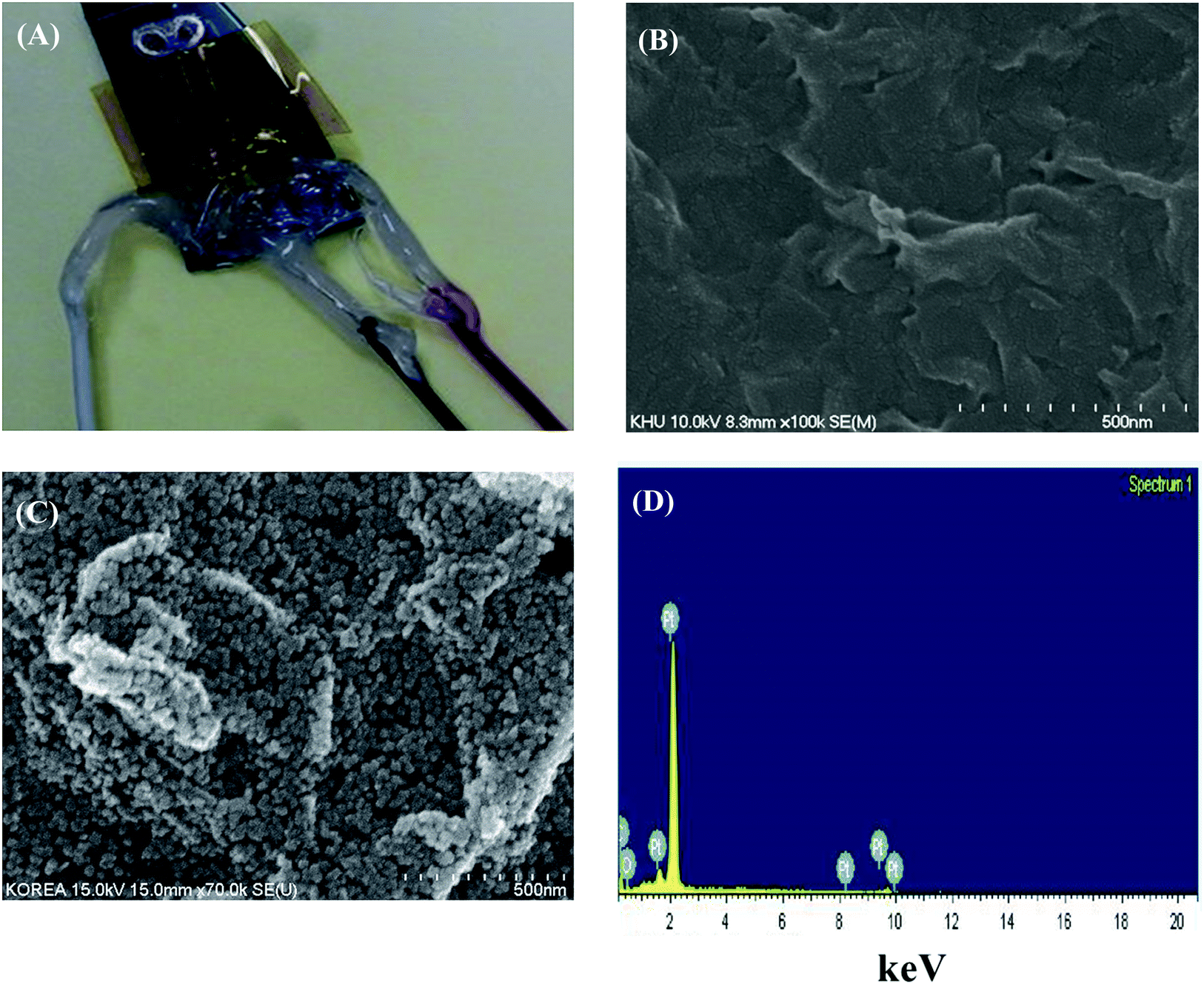 | ||
| Fig. 2 (A) Digital image of the developed biosensor; FESEM micrographs of (B) TRGO and (C) TRGO/PtNP, and (D) the corresponding EDX pattern of TRGO/PtNP. | ||
For this reason, the PtNP was well assembled on the TRGO network, forming a mutually perforating chain for a good transportation route of electron transfer from the matrix surfaces to the electrode. Moreover, a rough electrode surface is suitable for enzyme stability, enhancing the enzyme loading.
Elemental composition analysis of the PtNP decorated TRGO electrode was performed by EDX, as shown in Fig. 2(D). The peaks of C, O, and PtNPs are seen in the EDX analyzed data. The atomic percentages of C, O, and PtNP were 85.78%, 11.04%, and 3.18%, respectively, indicating that PtNP was successfully deposited by the electrochemical method under the given conditions.
The typical AFM image and height profile of TRGO are shown in Fig. 3. The thickness of the TRGO sheet is in the range of 1.1 to 10 nm in the cross sectional view across the flat area of the TRGO sheet, and the length is in the range of several micrometers. The observed thickness of the TRGO sheet reveals that the monolayer and a few layers were present in the developed TRGO.
 | ||
| Fig. 3 AFM image of the TRGO surface (profile respect to line chosen in the image). | ||
XPS was carried out to analyze the oxygen functional groups in GO and TRGO. Fig. 4(A) and (B) show the C1s spectra of GO, indicating a considerable degree of oxidation with other components, corresponding to different functional groups, i.e., C in the non-oxygenated ring in C![[double bond, length as m-dash]](https://www.rsc.org/images/entities/char_e001.gif) C (284.6 eV), C in the C–O bonds of oxygenated rings (286.6 eV), C in the CO bonds (288.2 eV), and C in the O–CO bonds (289.1 eV).24 After the reduction of GO, a peak (285.8 eV) was observed in the C1s spectra, including the C–C bonds of non-oxygenated rings.25 This result reveals that the oxygen functional groups were significantly reduced during the hydrothermal reduction, successfully forming RGO.
C (284.6 eV), C in the C–O bonds of oxygenated rings (286.6 eV), C in the CO bonds (288.2 eV), and C in the O–CO bonds (289.1 eV).24 After the reduction of GO, a peak (285.8 eV) was observed in the C1s spectra, including the C–C bonds of non-oxygenated rings.25 This result reveals that the oxygen functional groups were significantly reduced during the hydrothermal reduction, successfully forming RGO.
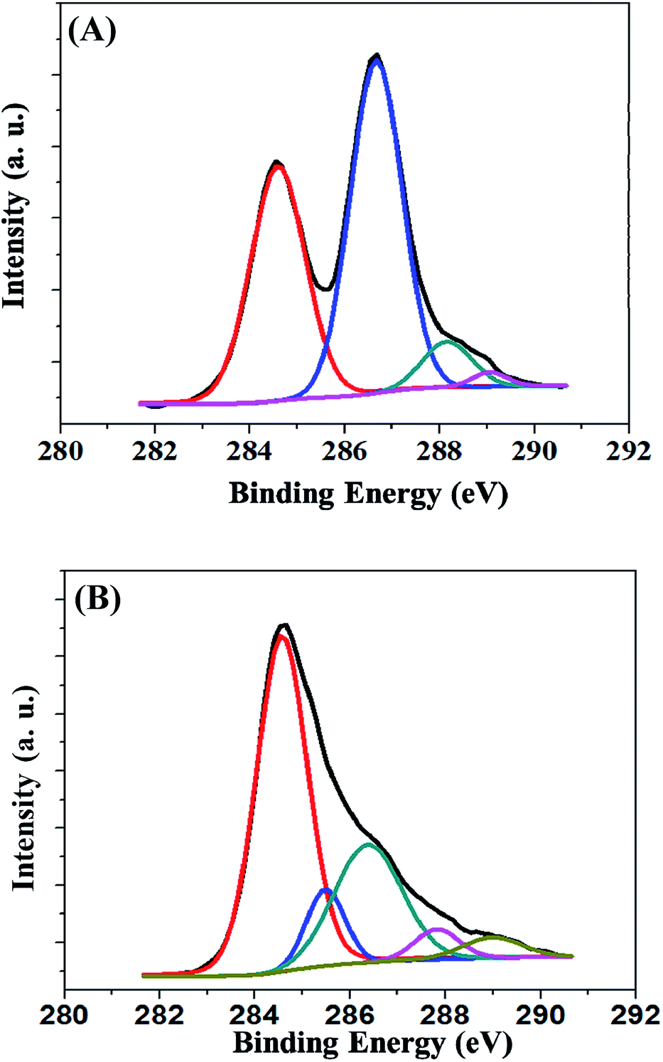 | ||
| Fig. 4 C1s XPS spectra of GO (A) and TRGO (B). | ||
Raman spectroscopy manifests the structural changes appearing during the reduction of GO to TRGO. The Raman spectra of GO and TRGO are shown in Fig. 5. The two prominent peaks, named the D band and G band, of GO appeared at 1350 and 1590 cm−1, respectively. Similarly, the peaks of TRGO appeared at 1349 and 1591 cm−1. The G band is involved in the in-plane vibration of sp2 bonded carbon atoms, whereas the D band is related to the vibrations of the carbon atoms with the sp3 electronic arrangement of disordered graphene. The ID/IG ratios of TRGO and GO are 1.28 and 0.89, respectively. This result reveals that reduction of GO occurred during the hydrothermal process.26 The number of layers of graphene material sheets were determined by the 2D band in the Raman spectrum. The 2D bands of GO and TRGO were located at ∼2693 and 2699 cm−1, respectively, indicating the presence of a few layers in the GO and TRGO sheets.27
 | ||
| Fig. 5 Raman spectra of GO and TRGO. | ||
3.2 Electrochemical characterization of the fabricated electrodes and biosensor
The purpose of removing TRGO from the counter and reference electrodes is to approximately insulate the three-electrode system by the CV technique. In this technique, the counter and the reference electrode of the device acted as the working electrode, and Hg/HgO and a Pt bar were used as the reference and counter electrodes, respectively; CV was conducted in NaOH solution under different potential windows. Initially, the voltage was applied from −1 V to +1 V for 10 cycles, as shown in Fig. 6(A). Under these conditions, no anodic peak was observed on the anodic curve; however, one cathodic peak appeared during the reduction reaction on the cathodic curve. This result indicates that TRGO still contains oxide groups and was reduced in alkaline solution during the CV. This electrochemical reduction creates defective RGO because of the diffusion of epoxy oxygen atoms on the TRGO surface.28 When more epoxy atoms are diffused on the TRGO sheet, more defective sites are produced on the TRGO surface. Consequently, the resistance of the electrode gaps increases, and a portion of the TRGO is removed from the electrodes. CVs of the counter and reference electrodes were recorded again at the potential range of −0.1 V to +2 V for 15 cycles. The purpose of the high potential is to generate oxygen gas bubbles by the oxidation of water,29 as well as to avoid the reduction of the oxide groups on TRGO, which can cause them to peel off from the electrode. The evolution of oxygen gas occurred at higher potential according to the equation (4OH− → O2 + 2H2O + 4e−). Complete removal of TRGO was observed on the surface of the two electrodes, and CV was performed again on the electrodes, as shown in Fig. 6(B). The inset of Fig. 6(B) shows the biosensor device after TRGO was etched from the counter and reference electrodes. TRGO was removed from the counter and reference electrodes, creating a good pattern on the substrate. The newly developed etching process is easier and more convenient for patterning RGO on the electrodes than other etching techniques, such as oxygen plasma etching. | ||
| Fig. 6 CVs for TRGO removal from the counter and reference electrodes in NaOH solution at (A) −1 V to 1 V and (B) −0.2 V to 2 V. (C) The CVs of (a) one and (b) two distributed working electrodes in 50 mM PBS, pH 7.4, scan rate: 50 mV s−1. | ||
CVs of the working electrodes (single- and double-electrode-based biosensors) were recorded in PBS, as shown in Fig. 6(C)(a) and (b). A peak was observed at ∼0.55 V in the cathodic curve. The peak at 0.55 V is because of the reduction of monolayer gold oxide.30 The peak intensity of the double working electrode-based sensor was nearly twice that of the single one, indicating that the two separate working electrodes were joined and acted as a series circuit.
The electroactive surface areas (ESA) of the TRGO modified electrode and the TRGO/PtNP modified electrode were evaluated by integrating the areas of the anodic peaks in the hydrogen region in 0.5 M H2SO4 solution at a scan rate of 50 mV s−1. The ESA was calculated by dividing the estimated charge by the charge per actual active area of the catalyst (0.21 mC cm−2). The geometric surface area of the pristine electrode was 0.0706 cm2, and the surface area of the pristine electrode was estimated to be 0.12 cm2. The ESAs for the TRGO modified electrode and the TRGO/PtNP electrode were estimated as 0.35 and 15.36 cm2, respectively.
3.3 Electrochemical performance of the fabricated biosensor for glucose detection
The CVs of the plain and TRGO coated electrodes are presented in Fig. 7(A)(a) and (b), respectively. The response current of the modified working electrodes is greater than that of the pristine electrode. The larger response is attributed to the higher catalytic activity of the TRGO coated electrode.31 CV of the TRGO/PtNP/chit–GOx/Nafion modified biosensor working electrodes was conducted in PBS solution, as shown in Fig. 7(A)(c). The oxidation peak of the working electrodes is not clearly visible on the anodic curve, indicating that GOx and Nafion formed a blocking layer against electron conduction. The CV of the working electrode was also measured in PBS with 2 mM glucose, as shown in Fig. 7(A)(d). The oxidation currents of the working electrodes on the anodic curve increased from 0.2 to 0.65 V in 2 mM glucose, greater than those of the working electrodes in PBS. This result indicates that the oxidation current increased proportionally with the amount of adsorbed OH− on the biosensor working electrodes in 2 mM glucose. Therefore, it is easy to determine the bias potentials for the biosensor to detect glucose from the CV curves. | ||
| Fig. 7 (A) CVs of the developed distributed electrodes: pristine (a), TRGO coated (b), TRGO/PtNPs/Ch–GOx/Nafion modified in PBS (c), and in PBS with 2 mM glucose (d), scan rate: 50 mV s−1. (B) Amperometric response of the biosensor in PBS (pH, 7.4, 50 mM). | ||
The current responses of the biosensor at 0.3, 0.4, and 0.5 V upon successive additions of different concentrations of glucose in PBS solution, and the corresponding calibration plots (the inset of the figure), are shown in Fig. 7(B)(a)–(c). The current increased instantly with increasing glucose concentration and rapidly reached the steady state. The response time of the biosensor was as fast as 5 s, exhibiting the observation range of 0.5 to 12 mM glucose with a sensitivity of 28.37, 41.18, and 34.22 μA mM−1 cm−2 at 0.3 V (a), 0.4 V (b), and 0.5 V (c), respectively. From these responses, the highest response was obtained at 0.4 V; the linear range was 0.00625 to 10 mM. The sensitivity and linear range of the as-fabricated sensor are higher than those of previously published reports, including a sensitivity of 14.41 μA mM−1 cm−2 and a linear range of 0 to 0.7 mM for GC/CNTs–CdTe/GOx/Nafion,32 38 μA mM−1 cm−2 and 0.05 to 0.5 mM for ITO/CdS–Au–Ch/GOx,33 7.4 μA mM−1 cm−2 and 0.5 to 10 mM for Al2O3/Pt/PPy/GOx,34 and 39.63 μA mM−1 cm−2 and 0.01 to 4.5 mM for GC/PSS/PAni/Pt-DENs/GOx/Pt-DENs.35 Various concentrations of glucose were detected by the fabricated biosensor at 0.4 V in PBS, as shown in Fig. 8(A). The detection limit of the biosensor was determined to be 0.0019 mM (a signal three times above noise). This limit of detection is much smaller than those previously reported, including detection limits of 0.1 mM for Pt/TiO2/RGO/PtNPs/GOx,36 0.18 mM for Au/Gr/AuNPs/Ch–GOx,2 0.01 mM for PET/Ti/Au/SDS-MWCNT/PDDA/GOx/PDDA,37 and 0.017 mM for GC/Ag-Pdop@CNT/GOx/Nafion.38
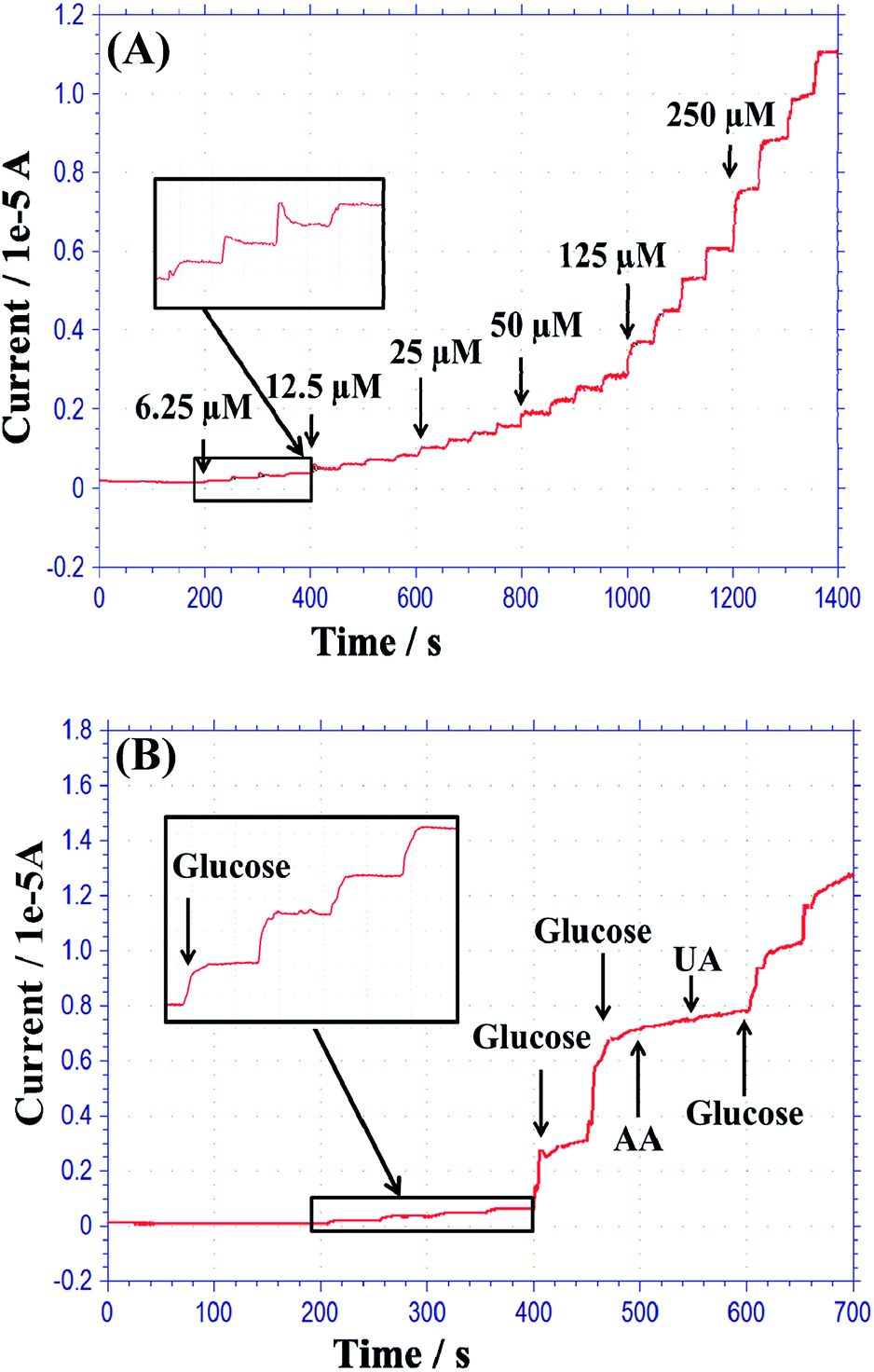 | ||
| Fig. 8 (A) Amperometric response of the biosensor in PBS to the successive addition of different concentrations (6.25, 12.5, 50, 125, and 250 μM) of glucose at 0.4 V. (B) The response of interference effects on the developed biosensor upon injection of 1.58 mM glucose, followed by 0.2 mM UA, 0.1 mM AA, and further injection of 0.5 mM glucose in PBS solution at 0.4 V (pH, 7.4). | ||
The current responses of possible interfering species, such as AA and UA, were studied by amperometry. Humans cannot synthesize ascorbic acid; they obtain it through diet or from supplements. Ascorbic acid excretion in human urine is around 0 to 1.12 mM per day.39 Contrastingly, uric acid excretion in urine is around 0.32 to 2.9 mM per day.40,41 0.2 mM UA and 0.1 mM AA were used in this study. These interfering anodic currents were lower than that of 7.12 μA for 1.58 mM glucose. The anodic responses are negligible for 0.1 mM AA and 0.2 mM UA, as shown in Fig. 8(B). In future, the fabricated glucose sensor will be improved for tolerance of higher concentrations of interference species. The stability of the fabricated biosensor was also observed for a period of four weeks. The sensitivity of the biosensor decreased only by 15.2% during that time, indicating that the sensor has long-term stability. The repeatability and reproducibility of the fabricated sensor were verified by amperometric response in PBS up to 4.5 mM glucose. The glucose sensor showed a relative standard deviation (RSD) of 3.15% for five repetitive measurements. This indicates that the fabricated sensor has good repeatability. In addition, four individual sensors were fabricated using the same process that was used for the developed glucose sensor. All the different biosensor electrodes showed an RSD of 6.4% in their amperometric responses, suggesting the appreciable reproducibility of the as-fabricated glucose sensor.
3.4 Determination of glucose in human urine
In general, urine should not contain any glucose. Glucose will penetrate the urine only when there is excess glucose in the blood and the kidney is too abounding to reabsorb the excess amount of glucose. The urinary glucose level of people with diabetes is often within the range of 2.8–5.6 mM,42 and the normal range is 0–0.8 mM. Therefore, easy and reliable methods for the observation of glucose in urine are highly desirable to diagnose diabetes, instead of a finger prick to obtain blood. In this study, urine samples were collected from a healthy person. Glucose was not found in the urine sample.The amperometric response of the biosensor upon continuous addition of different concentrations of human urine glucose is shown in Fig. 9, indicating that the biosensor responded rapidly to the addition of small amounts of urine glucose and reached the steady state (95% of the signal) within 5 s. The biosensor showed good linearity at the lower range detection of glucose in human urine. Therefore, the fabricated biosensor is suitable for detecting lower concentrations of glucose in human urine. In addition, 100 μL of the urine sample were added to 20 mL of 0.05 M PBS solution. Then, a certain concentration of standard glucose sample was injected into the urine and PBS diluted solution so that the concentration of glucose in the urine could be detected from the calibration curve, as shown in Table 1. The recovery of spiked glucose in the urine sample was observed in the range of 96.1 to 99.2%, and the RSD ranged from 3.8% to 6.1%; this reveals that the fabricated glucose sensor has good ability for glucose detection in human urine.
 | ||
| Fig. 9 Amperometric response of the fabricated glucose sensor to various urine glucose concentrations (12.5, 25, 50, 100, and 750 μM) in PBS (pH 7.4) at an applied potential of 0.4 V. | ||
| Sample | Spiked (μM) | Detected (μM) | Recovery (%) | RSD (%) |
|---|---|---|---|---|
| 1 | 25 | 24.8 | 99.2 | 3.8 |
| 2 | 250 | 240.2 | 96.1 | 4.3 |
| 3 | 1500 | 1470 | 98.0 | 4.9 |
| 4 | 2500 | 2438 | 97.5 | 5.3 |
| 5 | 3000 | 2923 | 97.4 | 6.1 |
4 Conclusions
A distributed working electrode-based glucose sensor was designed and successfully fabricated on a single chip. TRGO was synthesized and coated on the surface of the biosensor. The TRGO coated surface was patterned electrochemically. Afterward, platinum nanoparticles, an enzyme–chitosan mixture, and Nafion were decorated on the modified working electrodes. The developed biosensor exhibited high catalytic activity towards glucose oxidation, with a low response time, high sensitivity, and detection range of 5 s, 41.18 μA mM−1 cm−2, and 0.00625 to 12 mM, respectively. The developed biosensor also displayed acceptable interference activity and stability. Furthermore, the fabricated glucose sensor showed acceptable repeatability and reproducibility. The biosensor showed good linearity at a lower range and acceptable performance in detecting glucose in human urine. Thus, the developed biosensor is a good candidate for long-term urine glucose monitoring applications.Acknowledgements
This study was supported by the ICT R&D program of MSIP/IITP [2015(10041876)] and the Technological Innovation R&D Program funded by the Small and Medium Business Administration (SMBA), Korea. The authors are grateful to MiNDaP (Micro/Nano Device & Packaging Lab) group members at the Department of Electronic Engineering, Kwangwoon University for their technical discussion and support.References
- M. M. Rahman, A. Umar and K. Sawada, Sens. Actuators, B, 2009, 137, 327–333 CrossRef.
- C. Shan, H. Yang, D. Han, Q. Zhang, A. Ivaska and L. Niu, Biosens. Bioelectron., 2010, 25, 1070–1074 CrossRef CAS PubMed.
- H. W. Liaw, J. M. Chen and Y. C. Tsai, J. Nanosci. Nanotechnol., 2006, 6, 2396–2402 CrossRef CAS PubMed.
- X. Kang, Z. Mai, X. Zou, P. Cai and J. Mo, Anal. Biochem., 2007, 369, 71–79 CrossRef CAS PubMed.
- K. Tian, S. Alex, G. Siegel and A. Tiwari, Mater. Sci. Eng., C, 2015, 46, 548–552 CrossRef CAS PubMed.
- P. Santhosh, K. M. Manesh, S. Uthayakumar, S. Komathi, A. I. Gopalan and K. P. Lee, Bioelectrochemistry, 2009, 75, 61–66 CrossRef CAS PubMed.
- I. Katsounaros, W. B. Schneider, J. C. Meier, U. Benedikt, P. U. Biedermann, A. A. Auer and K. J. Mayrhofer, Phys. Chem. Chem. Phys., 2012, 14, 7384–7391 RSC.
- L. Qiang, S. Vaddiraju, D. Patel and F. Papadimitrakopoulos, Biosens. Bioelectron., 2011, 26, 3755–3760 CrossRef CAS PubMed.
- A. Chen and P. Holt-Hindle, Chem. Rev., 2010, 110, 3767–3804 CrossRef CAS PubMed.
- D. Pradhan, F. Niroui and K. T. Leung, ACS Appl. Mater. Interfaces, 2010, 2, 2409–2412 CAS.
- C. Yang, M. Zhou and Q. Xu, Nanoscale, 2014, 6, 11863–11870 RSC.
- H. A. Becerril, J. Mao, Z. Liu, R. M. Stoltenberg, Z. Bao and Y. Chen, ACS Nano, 2008, 2, 463–470 CrossRef CAS PubMed.
- A. Swietlikowska, M. Gniadek and B. Palys, Electrochim. Acta, 2013, 98, 75–81 CrossRef CAS.
- S. Pei and H. M. Cheng, Carbon, 2012, 50, 3210–3228 CrossRef CAS.
- X. Sun and Y. Li, Angew. Chem., Int. Ed., 2004, 43, 597–601 CrossRef PubMed.
- L. W. Zhang, H. B. Fu and Y. F. Zhu, Adv. Funct. Mater., 2008, 18, 2180–2189 CrossRef CAS.
- L. B. Luo, S. H. Yu, H. S. Qian and T. Zhou, J. Am. Chem. Soc., 2005, 127, 2822–2823 CrossRef CAS PubMed.
- R. Flyunt, W. Knolle, A. Kahnt, S. Eigler, A. Lotnyk, T. Häupl, A. Prager, D. Guldi and B. Abel, Am. J. Nano Res. Appl., 2014, 2, 9–18 Search PubMed.
- J. D. Benck, B. A. Pinaud, Y. Gorlin and T. F. Jaramillo, PLoS One, 2014, 10, 1–13 Search PubMed.
- R. L. McCreery, Chem. Rev., 2008, 108, 2646–2687 CrossRef CAS PubMed.
- Y. J. Lee, D. J. Park and J. Y. Park, IEEE Sens. J., 2008, 8, 1922–1927 CrossRef CAS.
- N. Ruecha, R. Rangkupan, N. Rodthongkum and O. Chailapakul, Biosens. Bioelectron., 2014, 52, 13–19 CrossRef CAS PubMed.
- M. F. Hossain and J. Y. Park, J. Electrochem. Soc., 2015, 162, B185–B192 CrossRef CAS.
- S. Some, Y. Kim, E. Hwang, H. J. Yoo and H. Y. Lee, Chem. Commun., 2012, 48, 7732–7734 RSC.
- M. F. Hossain, J. Yin and J. Y. Park, Jpn. J. Appl. Phys., 2014, 53, 08NC02 CrossRef.
- K. Ai, Y. Liu, L. Lu, X. Cheng and L. Huo, J. Mater. Chem., 2011, 21, 3365–3370 RSC.
- S. Petnikota, N. K. Rotte, V. V. S. S. Srikanth, B. S. R. Kota, M. V. Reddy, K. P. Loh and B. V. R. Chowdari, J. Solid State Electrochem., 2014, 18, 941–949 CrossRef CAS.
- C. Chen, W. Kong, H. M. Duan and J. Zhang, Phys. Chem. Chem. Phys., 2014, 16, 12858–12864 RSC.
- S. X. Guo, Y. Liu, A. M. Bond, J. Zhang, P. E. Karthik, I. Maheshwaran, S. S. Kumarb and K. L. N. Phani, Phys. Chem. Chem. Phys., 2014, 16, 19035–19045 RSC.
- B. J. Plowman, M. Mahajan, A. P. O'Mullane and S. K. Bhargava, Electrochim. Acta, 2010, 55, 8953–8959 CrossRef CAS.
- D. Zhang, H. Zhao, Z. Fan, M. Li, P. Du, C. Liu, Y. Li, H. Li and H. Cao, PLoS One, 2015, 10, e0130156 Search PubMed.
- Q. Liu, X. Lu, J. Li, X. Yao and J. H. Li, Biosens. Bioelectron., 2007, 22, 3203–3209 CrossRef CAS PubMed.
- J. Qian, S. Yan and Z. Xiao, J. Colloid Interface Sci., 2012, 366, 130–134 CrossRef CAS PubMed.
- E. M. I. M. Ekanayake, D. M. G. Preethichandra and K. Kaneto, Biosens. Bioelectron., 2007, 23, 107–113 CrossRef CAS PubMed.
- L. Xu, Y. Zhu, L. Tang, X. Yang and C. Li, J. Appl. Polym. Sci., 2008, 109, 1802–1807 CrossRef CAS.
- C. Feng, G. Xu, H. Liu, J. Lv, Z. Zheng and Y. Wu, J. Electrochem. Soc., 2014, 161, B1–B8 CrossRef CAS.
- X. B. Yan, X. J. Chen, B. K. Tay and K. A. Khor, Electrochem. Commun., 2007, 9, 1269–1275 CrossRef CAS.
- Y. Wang, L. Liu, M. Li, S. Xu and F. Gao, Biosens. Bioelectron., 2011, 30, 107–111 CrossRef CAS PubMed.
- J. A. Jackson, K. Wong, C. Krier and H. D. Riordan, Journal of Orthomolecular Medicine, 2005, 20, 259–261 Search PubMed.
- L. W. Xiang, J. Li, J. M. Lin and H. F. Li, J. Pharm. Anal., 2014, 4, 153–158 CrossRef CAS.
- N. Chauhan and C. S. Pundir, Anal. Biochem., 2011, 413, 97–103 CrossRef CAS PubMed.
- J. Zhang, C. Yang, C. Chen and X. Yang, Analyst, 2013, 138, 2398–2404 RSC.
| This journal is © The Royal Society of Chemistry 2016 |