The technology of straw sugar conversion to diol chemicals

Baohe Wanga, Peiqian Zhanga, Qiming Lub, Shuang Chen*a, Jing Zhua and Wenjie Luob
aKey Laboratory for Green Chemical Technology of Ministry of Education, Research and Development Center of Petrochemical Technology, Tianjin University, Tianjin 300072, P.R. China. E-mail: chenshuang@tju.edu.cn
bDancheng Caixin Sugar Industry Co. Ltd., Henan Province, P.R. China

Received 14th April 2016 , Accepted 20th June 2016

First published on 22nd June 2016


Abstract

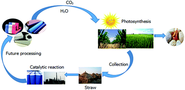
Straw sugar conversion to diols is one of the most favored routes for biomass utilization. In this paper, straw sugar was obtained by pretreating straw with ion exchange and decolorizing. The Sn–Co promoted RANEY® Ni catalyst for straw sugar hydrocracking to diols was prepared and characterized using BET, SEM, XRD, XPS and ICP. The yield of conversion of straw sugar to diols reached 50% under the optimum reaction conditions of 503 K at 11 MPa for 3 hours, with 15% catalyst content (solid–liquid mass ratio), 4 wt% alkali amount, pH 11.2–11.7, and 5 Nm3 h−1 hydrogen flow. The reaction mechanism was also hypothesized. This work may provide further guidance for the industrial production of diols from biomass.


1. Introduction

With the continuous development of the global chemical industry, diols are widely used, and in particular ethylene glycol and propylene glycol are very versatile.1 Glycol is mainly used to produce unsaturated polyester resins, plasticizers, polyester fibers, and surfactants, etc. It can also be used as an antifreeze and as brake fluid.2,3 There is a huge demand for ethylene glycol, which is produced mainly from ethylene, a petrochemical or bioethanol derived product. As a humectant, propylene glycol is widely used in non-ionic wash paints, pharmaceuticals, cosmetics and tobacco industries. However, the major industrial technologies of ethylene glycol and propylene glycol production use an oil-based route. According to previous reports, using an oil-based production process to produce 1 ton of ethylene glycol will consume about 2.5 tons of crude oil. This will further increase the global oil and energy crises, and is very unfavorable for sustainable human development. To overcome these weaknesses, the development of renewable biomass energy has drawn researchers’ attention.4–12 For instance, Caes et al.9 reported how cellulose can be organocatalytically converted into a platform chemical. Bobbink et al. reported a series of studies on the conversion of biomass with effective catalysis by well-defined nano-metal catalysts.12 China is a large agricultural country and has large straw resources. Straw sugar substitutes, polyols, for glucose production are even more promising. Developing the production of sugar alcohol from bio-chemical straw has many significant benefits. It can not only reduce the oil crisis, but can also be conducive to environmental protection.

Various catalysts such as calcite, dolomite, olivine and metal oxides have been investigated for sugar hydrocracking process.13–16 Nickel is considered as one of the most promising catalysts for sugar solution conversion into diols through the hydrocracking process.17–20 Zhang et al.18,21,22 used nickel-promoted tungsten carbide, mesoporous carbon supported tungsten carbide or SBA-15 supported Ni–W catalysts to obtain high selectivity glycol. Wang et al.23 used the cheaper Ni/ZnO, Ni–Cu/ZnO as catalyst and fiber polysaccharides as raw materials to prepare carbon glycols. Long et al.24 reported that nickel metal exhibited a better performance when compared with other metals such as Co and Fe, and Ru is found to have a higher catalytic performance and coke resistance than Ni in the hydrocracking process, but is limited by its high cost for large-scale applications.25–28 Many researchers have tried to develop excellent bimetallic catalysts. Deng et al.29 reported that the cellulose reaction on Ni particles and the isomerization of glucose to fructose and their C–C bond cleavage by retro-aldol condensation on SnOx domains. Wang et al.30 reported that combining Co with Ni/Al2O3 resulted in a higher catalytic performance and longer stability when compared with Ni/Al2O3 itself for the steam reforming of toluene and real tar derived from cedar wood. Nickel sintering and coke deposition generally occur during the hydrocracking process.31 Based on our previous study and combining with the above advantages of Sn–Co-modified supported catalysts, we prepared a Sn–Co promoted RANEY® Ni catalyst and applied it to the conversion of straw sugar to diol chemicals.

In this paper, straw was used as the raw material and then hydrolyzed with a high temperature steam acid solution. The process of straw sugar hydrocracking to diols over a Sn–Co promoted RANEY® Ni catalyst was optimized. This study may provide guidance for industrial production with great environmental and economic advantages.

2. Experimental

2.1 Materials

Straw, glucose (>99.5 wt%) and straw sugar (pretreated) were obtained from Dancheng Caixin Sugar Industry Co. LTD. H2 (purity > 99.99%) was from Tianjin Liufang gas Co. LTD. and sodium hydroxide (Analysis pure) was from Tianjin YuanLi Chemical.

2.2 Catalyst preparation

The catalyst was obtained from Dancheng Caixin Sugar Industry Co. LTD. Based on our previous study, the Sn–Co promoted RANEY® Ni catalyst was prepared as follows: the quaternary alloy Sn–Co–Ni–Al was prepared using a fusion method. This was then added to a 20% (mass fraction) sodium hydroxide solution, stirred for 90 min at 353 K and washed with distilled water until pH ∼ 7. The Sn–Co promoted RANEY® Ni catalyst was finally obtained with 68.33 wt% Ni, 10.22 wt% Al, 5.77 wt% Sn, and 2.15 wt% Co (ICP-OES Agilent Technologies).

2.3 Catalyst characterization

The BET surface area, pore volume and pore diameters of the catalyst were determined using N2 adsorption–desorption with a Quantachrome Corporation (FL, US) Autosorb 1-C Instrument.

The particle surface morphologies of the catalysts were characterized with a scanning electron microscope (SEM, SU8010, Hitachi, Japan) coupled with an energy dispersive X-ray detector (EDX).

The X-ray diffraction (XRD) patterns were obtained on a Rigaku D/Max-2500 diffractometer in step mode employing CuKα radiation (λ = 0.154 nm). The X-ray tube was operated at 40 kV and 150 mA in the range of 5–90°.

XPS studies were conducted on an Axis Ultra spectrometer (Kratos Analytical Ltd.) using monochromatic Al Kα radiation as a source power of 15 kV.

The content of the elements in the catalyst were determined using Vista-MPX inductively coupled plasma atomic emission spectroscopy (ICP-OES) (Varian Company, America). The instrument parameters were a high frequency transmitter power of 1.2 kW, with argon as the plasma gas and auxiliary gas.

2.4 Experiments

2.4.1 Pretreatment. Straw was cut with a cutting machine to a size of about 5–10 mm, and treated with a cyclone separator to remove impurities such as sand, dust, etc., then the straw was slowly added to the preprocessor followed by 0.6 wt% H2SO4 aqueous solution29 (solid–liquid mass ratio 2[thin space (1/6-em)]:[thin space (1/6-em)]1). Owing to its crystalline form and the number of hydrogen bonds involved, the hydrolysis of straw is significantly more challenging than that of starches. After stirring for 12 hours in the preprocessor, the cut straw still had a lot of solid insoluble components. In the next step, we used a steam explosion method with high pressure steam slowly passed over at 2.5 MPa and maintained the temperature at 473 K. After completion of the reaction, the exhaust valve relief was opened, the reactor pressure was lowered to atmospheric pressure within 30 seconds, and the straws were almost hydrolyzed.

We added plenty of activated carbon and heated to 353 K to decolorize, and then filtered through a plate and frame filter. The filtrate was passed through an ion exchange resin (D001MB and D301-F) to remove sulfuric acid, aldehydes, acids, etc. As a result, four kinds of pretreated straw sugar were generated (before and after ion-exchange, before and after decolorizing). The pathway of straw pretreatment is shown in Scheme 1.


image file: c6ra09670k-s1.tif
Scheme 1 The pretreatment pathway of straw.
2.4.2 Hydrocracking. A certain concentration of 35% pretreated straw sugar solution was added to the batch reactor with a certain amount of the catalyst after adjusting the pH value and then the reaction vessel was evacuated. The air remaining in the reactor was replaced with nitrogen and then the nitrogen was replaced with hydrogen. The reaction temperature and stirring speed were set, and high-pressure hydrogen gas was introduced to the reactor. The reaction pressure and temperature were maintained for 3 h. When the reactor had cooled to about 333 K, the gas was released (gas collection) and the catalyst separated. The reaction solution was filtered, vacuum distilled, dehydrated and weighed. After the reaction, the liquid products were analysed using high-performance liquid chromatography (Shimadzu LC-20A) while the gas phase products were analyzed using gas chromatography (Agilent Technologies). All of the above reactions were performed in a 1 L reactor under a speed of 1000 rpm. The product selectivities are reported on a carbon basis.

3. Results and discussion

3.1 Catalyst characterization

The BET surface area, pore volume and average pore diameter of the catalysts are listed in Table 1. As can be observed, the catalyst before use has a higher specific surface area (38.9 m2 g−1) than the used catalyst (20.9 m2 g−1). This may be due to reactive residues and coke on the surface of the used catalyst.
Table 1 Pore properties of the catalysts
Co–Sn/RANEY® Ni catalyst BET surface area (m2 g−1) Pore volume (cm3 g−1) Average pore diameter (nm)
Fresh 38.9 0.09 10.3
Used 20.9 0.06 11.9


As shown in Fig. 1, the images of the fresh and used catalysts show a typical granular characteristic. There is a synergistic effect from the combination of four elements in the catalyst. The electron micrograph obtained from the used catalyst showed a larger agglomeration of particles, which may be due to the sintering and coke after the catalytic reaction, which is in agreement with the BET results.


image file: c6ra09670k-f1.tif
Fig. 1 SEM images of the Sn–Co promoted RANEY® Ni catalyst: (a) fresh catalyst, and (b) used catalyst.

The X-ray diffraction pattern of the fresh and used catalysts is shown in Fig. 2(a) and (b), respectively. The fresh catalyst contained different phases including Al–Co, Al–Ni etc. As can be observed, the catalyst contained various alloy phases, all of which are important phases in the hydrogenation reaction. SnOx species did not give any XRD peaks, suggesting that a small amount of Sn modified RANEY® Ni could not form crystals.32,33 For the catalyst after use, different identified phases were observed such as Al–Co, Al–Ni, Co–Sn, carbon etc. The diffraction peak intensity of the used catalyst decreased and the peak broadening present suggests a certain amorphous characteristic. This may be due to the carbon covering the used catalyst surface according to the SEM and BET results.


image file: c6ra09670k-f2.tif
Fig. 2 XRD patterns of the Sn–Co promoted RANEY® Ni catalyst: (a) fresh catalyst, and (b) used catalyst.

Table 2 shows the XPS results of the fresh catalyst and used catalyst. In the Ni 2p region, three peaks were observed at binding energies of 852.72–853.09 eV, 870.00–870.34 eV and 853.10 eV, corresponding to the characteristic peaks of Ni–Co 2p1/2, Ni–Co 2p3/2 and Ni–Al 2p3/2, which indicate that the surface Ni species were present as intermetallic/alloys in these catalysts.34,35 The elements Al and Co were also present as zero-valent alloys. In the Sn 3d region, as shown in Table 2, the Sn–Co/RANEY® Ni samples exhibited two symmetrical signals at binding energies of 486.3–487.1 eV and 494.8–495.6 eV, which can be respectively assigned to Sn 3d5/2 and Sn 3d3/2 for oxidized tin, Sn2+ and Sn4+.36,37 These results indicate that the SnOx species (SnO and/or SnO2) were the main Sn species at the surface of the Sn–Co/RANEY® Ni samples.

Table 2 XPS properties of the catalysts
Co–Sn/RANEY® Ni catalyst Binding energies (eV)
Ni 2p Al 2p Co 2p Sn 3d
Fresh 852.70–853.11, 853.10, 870.00–870.40 73.38–73.91 484.65–484.73 486.3–487.1, 494.8–495.6
Used 852.70–853.11, 853.10, 870.00–870.40 73.38–73.91 484.65–484.73 486.3–487.1, 494.8–495.6


3.2 Pretreatment of the raw material

The pretreatment of the raw material is very important for the hydrocracking process. Fig. 3 shows the result of the hydrogenation cracking of pure glucose compared with straw sugar (before and after pretreatment).
image file: c6ra09670k-f3.tif
Fig. 3 The effect of pretreatment on hydrocracking. image file: c6ra09670k-u1.tif Dibasic alcohol yield, image file: c6ra09670k-u2.tif the total yield, and image file: c6ra09670k-u3.tif the selectivity of glycol: (a) glucose, (b) straw sugar after decolorizing and ion-exchange, and (c) straw sugar without pretreatment.

The figure shows that the straw sugar after ion-exchange and decolorizing gave a higher yield than the untreated sample. The straw sugar after pretreatment showed as good a performance as pure glucose, indicating that it was appropriate for the reaction. For the untreated straw sugar solution, in the hydrocracking process, pigments and other kinds of residual ions may damage the structure of the catalyst and deactivate the catalyst. So, in the next trials, we chose straw sugar after ion-exchange and decolorizing as the experimental material.

3.3 Catalyst content

As shown in Fig. 4, with increasing amount of catalyst, the yield of dihydric alcohols firstly increased and then gradually decreased. This was because when the catalyst amount is too small, the raw material cannot be fully converted. However, when the catalyst amount is too large, the viscosity of the reaction system increases, which is not conducive to the reaction, either. The yield of diol reached a maximum at a catalyst amount of 15% (solid–liquid mass ratio). Thus, the optimum amount of catalyst was chosen as 15% (solid–liquid mass ratio).
image file: c6ra09670k-f4.tif
Fig. 4 The effect of catalyst dosage on hydrocracking.

3.4 Alkali content and pH

Research suggests that the sugar solution is slightly acidic. As the reaction progresses, the degree of ionization grows and continuously produces trace amounts of organic acid. The catalyst will be gradually corroded as Ni metal transforms into Ni ions, and its activity will be reduced. Adding alkaline to the reaction is a good solution. Alkaline can quickly neutralize the acetic acid produced, which is good for the hydrogenation reaction of glucose. Alkaline can increase the electronic ability of metal atoms on the catalyst surface active centers, which is favorable for hydrogen absorption. The effect of base additives agreed with the result of Ning Yan and co-workers in the hydrogenation reaction of toluene over a Ni7Au3 bimetallic catalyst, in which they reported that stronger bases with hydroxyl ions (such as NaOH, KOH, and LiOH) were able to increase the hydrogenation activity to a larger extent.10

Fig. 5 shows the effect of pH and amount of NaOH on hydrocracking. With increasing amounts of alkali (the mass percentage of alkali and straw sugar), the diol yield gradually increases and then decreases. When 4 wt% alkali was added (measured at the end of the experiment), the highest glycol yield of 49.09% was obtained.


image file: c6ra09670k-f5.tif
Fig. 5 The effect of NaOH amount and pH on the yield of diol.

A small amount of acetic acid, lactic acid, and formic acid, etc. will be produced during the hydrocracking process of straw sugar. Adding alkali can neutralize the generated acid and has a protective effect on the catalyst. But excess base may inhibit the conversion of straw sugar to glycol. The optimal pH value for hydrocracking was between 11.2 and 11.7.

3.5 Reaction temperature

Based on reaction kinetics, the higher the reaction temperature is, the faster the reaction speed achieves. The effect of reaction temperature on the hydrocracking is shown in Fig. 6. With the increase in reaction temperature, the diol yield increased rapidly and then decreased.
image file: c6ra09670k-f6.tif
Fig. 6 The effect of reaction temperature on hydrocracking.

When the temperature reached at 503 K, the yield of the diol reached 45.66%. As the temperature rises, the reaction rate is accelerated. However, the product selectivity of the secondary reaction increases at the same time, leading to a decrease in the diol yield. Thus, 503 K was the suitable temperature for the reaction.

3.6 H2 flow

It can be seen from Fig. 7 that the yield of diol increased with the increase in hydrogen flow. But from 5 Nm3 h−1 to 7 Nm3 h−1, the increase in diol yield was not so obvious. Considering the cost and the yield of diol, a hydrogen flow of 5 Nm3 h−1 was better for the straw sugar hydrocracking reaction.
image file: c6ra09670k-f7.tif
Fig. 7 The effect of H2 flow on hydrocracking.

3.7 Reaction pressure

The effect of reaction pressure on hydrocracking is shown in Fig. 8.
image file: c6ra09670k-f8.tif
Fig. 8 The effect of reaction pressure on hydrocracking.

For a 1 L reactor, the pressure was difficult to control. Therefore, under the same conditions, we used both a 1 L and a 10 L reactor to perform the reaction. The yield of the diol increased with the increase in pressure. The influence of the reaction pressure on the reaction was mainly on the hydrogen pressure. As the reaction pressure increased, the hydrogen concentration increased and provided more chances for the hydrogen atoms to adsorb on the catalyst surface in contact with glucose, which then resulted in a higher diol yield. When the pressure was higher than 11 MPa, the increase in the diol yield was more moderate. Considering the energy consumption, the optimum reaction pressure for the reaction was 11 MPa.

3.8 Reaction mechanism of straw sugar hydrocracking

The reaction of hydrocracking to diols was conducted with pretreated straw sugar (shown as glucose and xylose in the mechanism in Scheme 2) as the raw material. Nickel is one of catalysts for O–H, C–H and C–C cracking during the hydrocracking process. It is considered as one of the most promising catalysts for the hydrocracking process.17,37,38
image file: c6ra09670k-s2.tif
Scheme 2 The reaction pathway over Sn–Co promoted RANEY® Ni catalyst.20,29,38

The effect of SnOx on the diol selectivity appears to be related to their effect on the hydrogenation activity of the glucose reaction on the Ni particles and the isomerization of glucose to fructose and their C–C bond cleavage by a retro-aldol condensation on the SnOx domains. Fructose degrades via a retro-aldol condensation on SnOx to form glyceraldehyde and dihydroxyacetone intermediates, which undergo hydrogenation to glycerol and further to 1,2-propanediol, or dehydration to pyruvaldehyde.29,33 The pyruvaldehyde intermediate then converts competitively to acetol and lactic acid salt via hydrogenation on Ni and a benzilic acid rearrangement with SnOx, respectively.29 The glycoaldehyde intermediate is ultimately hydrogenated to ethylene glycerol on Ni. Sorbitol is converted through two different pathways (presented in Scheme 2).18–20

The dominant pathway is sorbitol C–C and C–O hydrogenolysis, forming mainly C3 compounds such as glycerol, 1,2-propanediol and ethylene glycol. At the same time, small amounts of xylose in the straw sugar solution form xylitol via hydrogenation, and also degrades by retro-aldol condensation and hydrogenation to form ethylene glycol and glycerol.

3.9 Catalyst recycling, product separation and cost analysis

Industrial production is conducted in a continuous slurry bed reactor. The reaction products inevitably entrain a little amount of catalyst when exiting the reactor, resulting in a loss of catalyst. Thus, solid–liquid separation of the entrained catalyst is needed by means of sedimentation separation. A pump continuously recycles the catalyst to the reactor, while the liquid phase is cooled and then sent to a multi-effect distillation operation.

First, a small amount of the light components in the production reaction, such as methanol, ethanol and other substances are separated from the head of the light component removal column. The bottom liquid without any light component removes most of the water after multi-effect distillations, and then removes all the water using a dehydration tower. The bottom liquid, after removal of water, is sent to a products separation column to obtain the pure diols, and then the remaining fluid is sent to a wiped film evaporator to increase the recovery rate of the diols. Thereby, the anhydrous diols are obtained. The flow chart is shown in Fig. 9.


image file: c6ra09670k-f9.tif
Fig. 9 Process flow diagram. (B1) Light component removal column, (B2) multi-effect distillation, (B3) dehydration tower, (B4) product separation column, (B5) wiped film evaporator, (1) straw sugar, (2) light components, (3) wastewater treatment, (4) pure diols, and (5) heavy components.

We used the project “100[thin space (1/6-em)]000 tons per year of bio-chemical alcohol prepared from straw” as an example for an investment estimate. The estimated total investment is 103 million dollars, including 80 million dollars of fixed assets investment and 23 million dollars of industrial investment.

4. Conclusions

Straw sugar pretreated by decolorizing and ion-exchange was the best source for the production of diol chemicals. The technological process of straw sugar hydrocracking over Sn–Co promoted RANEY® Ni catalyst was optimized. The yield of diols reached 50% under the conditions of 15% (solid–liquid mass ratio) of catalyst, 503 K reaction temperature, 11 MPa reaction pressure, 4 wt% alkali amount and 5 Nm3 h−1 hydrogen flow in a 1 L reactor under a speed of 1000 rpm for 3 hours. The reaction pathway of straw sugar hydrocracking to diols over Sn–Co promoted RANEY® Ni catalyst was hypothesized. It provides a feasible technology for the industrial production of diols from straw.

Acknowledgements

This research was supported by National High-tech Research and Development Projects (863) of China (no. 2014AA021901).

References

  1. X. Liu, X. Wang, S. Yao, Y. Jiang, J. Guan and X. Mu, ChemInform, 2014, 46, 49501–49520 Search PubMed.
  2. C. H. Christensen, J. Rass Hansen, C. C. Marsden, E. Taarning and K. Egeblad, ChemSusChem, 2008, 1, 283–289 CrossRef CAS PubMed.
  3. A. J. Ragauskas, C. K. Williams, B. H. Davison, G. Britovsek, J. Cairney, C. A. Eckert, W. J. Frederick, J. P. Hallett, D. J. Leak and C. L. Liotta, Science, 2006, 311, 484–489 CrossRef CAS PubMed.
  4. J. V. Haveren, E. L. Scott and J. Sanders, Biofuels, Bioprod. Biorefin., 2008, 2, 41–57 CrossRef.
  5. A. Kruse, A. Funke and M. M. Titirici, Curr. Opin. Chem. Biol., 2013, 17, 515–521 CrossRef CAS PubMed.
  6. A. M. Ruppert, W. Kamil and P. Regina, Angew. Chem., Int. Ed., 2012, 43, 2564–2601 CrossRef PubMed.
  7. C. V. Stevens, Chem. Power., 2011, 200–231 Search PubMed.
  8. E. Taarning, C. M. Osmundsen, X. Yang, B. Voss, S. I. Andersen and C. H. Christensen, Energy Environ. Sci., 2011, 4, 793–804 CAS.
  9. B. R. Caes, M. J. Palte and R. T. Raines, Chem. Sci., 2012, 4, 196–199 RSC.
  10. Y. Wang, S. De and N. Yan, Chem. Commun., 2016, 52, 6210–6224 RSC.
  11. N. Yan and P. J. Dyson, Curr. Opin. Chem. Eng., 2013, 2, 178–183 CrossRef.
  12. F. D. Bobbink, J. Zhang, Y. Pierson, X. Chen and N. Yan, Green Chem., 2015, 17, 1024–1031 RSC.
  13. D. Sutton, B. Kelleher and J. R. H. Ross, Fuel Process. Technol., 2001, 73, 155–173 CrossRef CAS.
  14. D. A. Constantinou, J. L. G. Fierro and A. M. Efstathiou, Appl. Catal., B, 2010, 95, 255–269 CrossRef CAS.
  15. H. Noichi, A. Uddin and E. Sasaoka, Fuel Process. Technol., 2010, 91, 1609–1616 CrossRef CAS.
  16. M. Lu, P. Lv, Z. Yuan and H. Li, Renewable Energy, 2013, 60, 522–528 CrossRef CAS.
  17. N. Ji, T. Zhang, M. Zheng, A. Wang, H. Wang, X. Wang and J. G. Chen, Angew. Chem., Int. Ed., 2008, 47, 8510–8513 CrossRef CAS PubMed.
  18. J. Na, Z. Tao, M. Zheng, A. Wang, W. Hui, X. Wang, Y. Shu, A. L. Stottlemyer and J. G. Chen, Catal. Today, 2009, 147, 77–85 CrossRef.
  19. Y. Zhang, A. Wang and T. Zhang, Chem. Commun., 2010, 46, 862–864 RSC.
  20. N. Shigeto, O. Ritsuro, T. Yasuhiro, M. Naoko and M. Tatsuo, Green Chem., 2013, 16, 695–707 Search PubMed.
  21. J. Pang, A. Wang, M. Zheng and T. Zhang, Chem. Commun., 2010, 46, 6935–6937 RSC.
  22. L. Ning and G. W. Huber, J. Catal., 2010, 270, 48–59 CrossRef.
  23. X. Wang, F. Wu, S. Yao, Y. Jiang, J. Guan and X. Mu, Chem. Lett., 2012, 41, 476–478 CrossRef CAS.
  24. R. Q. Long, S. M. Monfort, G. B. Arkenberg, P. H. Matter and S. L. Swartz, J. Catal., 2012, 2, 264–280 CAS.
  25. J. R. Mcmanus, E. Martono and J. M. Vohs, Catal. Today, 2014, 237, 157–165 CrossRef CAS.
  26. O. V. Manaenkov, V. G. Matveeva, E. M. Sulman, A. E. Filatova, O. Y. Makeeva, O. V. Kislitza, A. I. Sidorov, V. Y. Doluda and M. G. Sulman, J. Catal., 2014, 57, 1476–1482 CAS.
  27. D. Gericke, D. Ott, V. G. Matveeva, E. Sulman, A. Aho, D. Y. Murzin, S. Roggan, L. Danilova, V. Hessel and P. Loeb, RSC Adv., 2015, 5, 15898–15908 RSC.
  28. A. Fukuoka and P. L. Dhepe, Angew. Chem., Int. Ed., 2006, 45, 5161–5163 CrossRef CAS PubMed.
  29. T. Deng and H. Liu, J. Mol. Catal. A: Chem., 2014, 388–389, 66–73 CrossRef CAS.
  30. W. Lei, D. Li, M. Koike, H. Watanabe, Y. Xu, Y. Nakagawa and K. Tomishige, Fuel, 2013, 112, 654–661 CrossRef.
  31. C. Wu and P. T. Williams, Appl. Catal., B, 2009, 87, 152–161 CrossRef CAS.
  32. A. Onda, T. Komatsu and T. Yashima, J. Catal., 2001, 201, 13–21 CrossRef CAS.
  33. T. Y. Deng and H. C. Liu, Green Chem., 2012, 15, 116–124 RSC.
  34. L. Sangaletti, L. E. Depero, P. S. Bagus and F. Parmigiani, Chem. Phys. Lett., 1995, 245, 463–468 CrossRef CAS.
  35. N. H. Turner and A. M. Single, Surf. Interface Anal., 1990, 15, 215–222 CrossRef CAS.
  36. D. L. Hoang, S. Farrage, J. Radnik, M. Pohl, M. Schneider, H. Lieske and A. Martin, Appl. Catal., A, 2007, 333, 67–77 CrossRef CAS.
  37. Y. Zhou and S. M. Davis, Catal. Lett., 1992, 15, 51–55 CrossRef CAS.
  38. J. Sun and H. Liu, Catal. Today, 2014, 234, 75–82 CrossRef CAS.

This journal is © The Royal Society of Chemistry 2016
Click here to see how this site uses Cookies. View our privacy policy here.