 Open Access Article
Creative Commons Attribution 3.0 Unported Licence
Continuous flow synthesis and cleaning of nano layered double hydroxides and the potential of the route to adjust round or platelet nanoparticle morphology
Andreas
Flegler
a,
Michael
Schneider
ab,
Johannes
Prieschl
a,
Ralph
Stevens
c,
Thomas
Vinnay
d and
Karl
Mandel
*ab
aFraunhofer Institute for Silicate Research ISC, Neunerplatz 2, 97082 Wuerzburg, Germany. E-mail: karl-sebastian.mandel@isc.fraunhofer.de
bDepartment of Chemical Technology of Materials Synthesis, University of Wuerzburg, Roentgenring 11, 97070 Wuerzburg, Germany
cNetherlands Organisation for Applied Scientific Research TNO, De Rondom 1, NL-5612 AP Eindhoven, The Netherlands
dCarl Padberg Zentrifugenbau GmbH, Geroldsecker Vorstadt 60, 77933 Lahr, Germany
First published on 7th June 2016
Abstract
Here, we report a continuous flow synthesis of nano LDH, comprising a continuous precipitation process using static mixers and followed by an immediate cleaning process via a semi-continuous centrifuge to obtain the final product in one-go. Via this synthesis setup, it is possible to independently vary the concentrations of the reactants during precipitation and at the same time ensure constant reaction conditions and an immediate “quenching” of the precipitate due to “on the flow”-washing. We found that this paves the way to adjust the synthesis parameters in a way that the final morphology of the nano-LDH particles can be controlled to be either round or platelet-like.
1. Introduction
Anionic clays, so called layered double hydroxides (LDH) are a highly interesting class of layered materials due to their broad application potential. The prototype of a LDH is hydrotalcite [Mg0.75Al0.25(OH)2](CO3)0.125·0.5H2O. The positively charged layers allow anions to be intercalated.1The layered structure, in conjunction with its positively charged nature and more importantly the high water content of the structure, turns LDH into highly interesting building-blocks for a remarkably broad range of applications. The most important fields of application are as adsorbers for anions, adsorbers for gases, drug containers, components for electrochemical storage devices and flame-retardants.2–25 The selective adsorption of anions such as phosphate in waste water, a currently hot topic, has been reported frequently in recent research to be potentially successful with LDH.2–9 Moreover, adsorption of gases is a promising topic with respect to CO2 capture.10–15 Since various substances can be intercalated within the layered structure, LDHs have also attracted much attention with respect to drug intercalation, for instance, in the case of ibuprofen, fenbufen or indomethacin.16–21 Recently, a nice overview work has been published, reviewing the various application possibilities of LDHs in electrochemistry, such as their use as electrode materials in supercapacitors, as electrocatalyst in fuel cells, metal–air batteries or as anode material in lithium-ion batteries.22
Last but not least, due to the water and carbon dioxide release upon calcination, the reaction to ceramic-tar-like materials at high temperatures and the overall endothermic nature of the reactions when heating up the material, makes these structures promising candidates for flame-retardants, bearing the potential to ultimately replace halogenated organic flame-retardants in the future.23–25
For all these applications, it is desired to make the LDH entities as small as possible, i.e., synthesise nano-LDH, as this comes with the advantage of a highly reactive surface and the fact that more active spots (LDH particles) are available for a given mass of material, i.e., the smaller the particles, the higher the chance to achieve a very finely and homogeneously distributed filling e.g. within polymers for flame retardancy. Moreover, depending on the application, it might be desired to obtain different shapes for the nanoparticles. Per se, LDH has a platelet-like shape as this comes from the native crystal structure of the particles.1,6,16,17,26 To best of our knowledge, there is only one work by the group of O'Hare that reported on having obtained spherically shaped nano LDH. This shape evolution was attributed to the synthesis at pH conditions above the iso-electric point region of LDH.10
In this work, we report on a process we developed, to produce MgAl-LDH nanoparticles under constant reaction conditions via continuous precipitation using static mixers. Continuous syntheses approaches of LDH have already been reported previously. Chang et al.27 reported the preparation of LDH at steady state conditions via a continuous feed of reactants to a stirred batch reactor of which the continuous effluent is collected. The approach is appealing yet difficult to achieve in exact reproducibility. Another more recent work reports on a continuous-flow hydrothermal reactor that can be used to produce nano-LDH continuously.28 The draw-back is, that the equipment required for a hydrothermal process is rather expensive.
The static mixer approach we report herein is a much simpler setup using only low budget components (a plastic–static mixer is available for a few dollars).
It guarantees constant reaction conditions and, due to the spiral mixer architecture, a very homogenous mixture of reactants.
Subsequently, we combine this synthesis directly on the flow with an innovative washing process. Therefore, we introduce a prototype of a semi-continuous tubular centrifuge.
Via transferring the whole synthesis and washing process to a continuous flow/one-go setup, it is possible to vary the reactants concentrations during precipitation independently. Since the precipitated product is immediately washed on the flow, the precipitated product is immediately “quenched” after synthesis. Compared to processes that collect the precipitation product in a batch container first, the advantage of our method is that any mixing of precipitants of different “generations” (with respect to evolution time) can be excluded and moreover, any ageing of the product is prohibited. With this method, it is possible to study the influence of precursor concentration variations with respect to the nanoparticle product obtained.
2. Experimental
2.1. Establishing a continuous synthesis and washing process for MgAl LDH
Precursor dissolution. For the preparation of nano LDH, containing magnesium and aluminium with a molar ratio of 2
![[thin space (1/6-em)]](https://www.rsc.org/images/entities/char_2009.gif) :
:![[thin space (1/6-em)]](https://www.rsc.org/images/entities/char_2009.gif) 1, 57.15 g (0.28 mol) magnesium chloride hexahydrate (MgCl2·6H2O, abcr GmbH) and 33.94 g (0.14 mol) aluminium chloride hexahydrate (AlCl3·6H2O, abcr GmbH) were dissolved in 250 ml deionized H2O under stirring at 70 °C (SOLUTION A). Simultaneously, 44.99 g (1.125 mol) sodium hydroxide (NaOH, VWR) and 7.46 g (0.07 mol) sodium carbonate (Na2CO3, abcr GmbH) were dissolved in 250 ml deionized H2O under stirring (SOLUTION B).
1, 57.15 g (0.28 mol) magnesium chloride hexahydrate (MgCl2·6H2O, abcr GmbH) and 33.94 g (0.14 mol) aluminium chloride hexahydrate (AlCl3·6H2O, abcr GmbH) were dissolved in 250 ml deionized H2O under stirring at 70 °C (SOLUTION A). Simultaneously, 44.99 g (1.125 mol) sodium hydroxide (NaOH, VWR) and 7.46 g (0.07 mol) sodium carbonate (Na2CO3, abcr GmbH) were dissolved in 250 ml deionized H2O under stirring (SOLUTION B).
Continuous precipitation. To realise a continuous precipitation process resulting in a homogeneous LDH suspension and a reproducible, constant viscosity, both solutions A and B (at RT) were brought in contact in a static spiral mixer (Series MXR 160, Nordson EFD) consisting of 30 mixing elements. The mixing effect was only caused by the flow of the two fluids being pumped with a peristaltic pump (MCP, ISMATEC). In the static spiral mixer, the precipitation process started immediately. The architecture of the mixer is such that the mixing elements are rotated spirally by 180° in an alternating way to the right and left side, see Fig. 1. The geometry of this kind of mixing system forced the two liquids to get in contact and yield the precipitation reaction highly precisely defined in space and time.
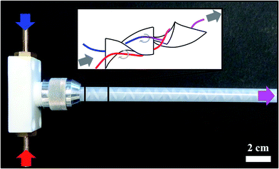 | ||
| Fig. 1 Photograph of the static mixer used in this work along with a schematic depiction of the spiral mixing elements. | ||
A whitish, homogeneous LDH suspension left the static mixer. In case 1, case 2 and case 3 (see below), the product was collected in a beaker and in case 4 (see below and see Fig. 2), the product directly entered a semi-continuous tubular centrifuge (CEPA type Z11) at a flow rate of 16.7 l h−1.
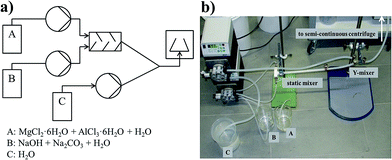 | ||
| Fig. 2 (a) Schematic process flowsheet of the continuous LDH synthesis with (b) the corresponding photograph of the setup. | ||
In all cases, washing steps were included to obtain a clean product, however in a different manner, as described below. The pH and conductivity values of LDH were measured during all the washing experiments.
In case 2, 5 ml of the collected LDH reaction product suspension was diluted with 20 ml of deionised water (immediate dilution factor 4) and centrifuged once, making use of a conventional lab centrifuge (Z513 K, HERMLE) for 10 min at a rotation speed of 2500 rpm.
In case 3 washing experiments were carried out using a semi-continuous tubular centrifuge. Here, 500 ml of collected LDH reaction product suspension was pumped with a flow rate of 16.3 l h−1 undiluted (case 3a), or diluted (case 3b) with 2000 ml of deionized H2O (i.e., immediate dilution factor of 4), into the semi-continuous tubular centrifuge, which rotated at a speed of 25![[thin space (1/6-em)]](https://www.rsc.org/images/entities/char_2009.gif) 000 rpm. The resulting LDH gel was harvested after centrifugation and redispersed in deionized H2O.
000 rpm. The resulting LDH gel was harvested after centrifugation and redispersed in deionized H2O.
In case 4 the LDH suspension with a flow rate of 3.4 l h−1 was pumped together with a constant flow of deionized H2O (flow rate 13 l h−1). In other words the LDH suspension was (cumulatively) diluted by a factor of 4 and pumped (flow rate 16.3 l h−1) directly into the semi-continuous tubular centrifuge rotating at a speed of 25![[thin space (1/6-em)]](https://www.rsc.org/images/entities/char_2009.gif) 000 rpm (see Fig. 2). The resulting continuously produced LDH gel was harvested after centrifugation and redispersed in deionized H2O.
000 rpm (see Fig. 2). The resulting continuously produced LDH gel was harvested after centrifugation and redispersed in deionized H2O.
The high speed rotor (Fig. 3a), with a maximum speed of 60![[thin space (1/6-em)]](https://www.rsc.org/images/entities/char_2009.gif) 000 rpm, can achieve a relative centrifugal force (RCF) up to 80
000 rpm, can achieve a relative centrifugal force (RCF) up to 80![[thin space (1/6-em)]](https://www.rsc.org/images/entities/char_2009.gif) 000 g-forces. The suspension is injected at the rotors bottom via a nozzle (Pos. 1), entering immediately the rotors accelerator (Pos. 2). Within a split second, the liquid is accelerated to nearly full rotor speed. As a result of high g-force, the liquid attaches to the rotor's wall in a nearly cylindrical shape (rotation paraboloid, Pos. 3), flowing to the head of the rotor towards the weir (Pos. 5), while the particles are sedimenting (Pos. 4) in accordance to Stokes' law. By sticking to the wall of the rotor, the particles remain inside, while the liquid leaves the rotor via the weir and the collection trays (Pos. 6).
000 g-forces. The suspension is injected at the rotors bottom via a nozzle (Pos. 1), entering immediately the rotors accelerator (Pos. 2). Within a split second, the liquid is accelerated to nearly full rotor speed. As a result of high g-force, the liquid attaches to the rotor's wall in a nearly cylindrical shape (rotation paraboloid, Pos. 3), flowing to the head of the rotor towards the weir (Pos. 5), while the particles are sedimenting (Pos. 4) in accordance to Stokes' law. By sticking to the wall of the rotor, the particles remain inside, while the liquid leaves the rotor via the weir and the collection trays (Pos. 6).
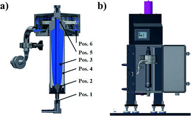 | ||
| Fig. 3 (a) Working principle and (b) sketch of the tubular centrifuge used for down-stream processing. | ||
The working principle of the centrifuge is depicted in Fig. 3a, a technical drawing of the centrifuge is shown in Fig. 3b.
2.2. Variation of reaction conditions via the continuous synthesis process to control the morphology of the nano-LDH
Temperature variation. All precipitation experiments were carried out at room temperature (25 °C). To exclude the influence of temperature variations during precipitation, the synthesis was carried out once, at 60 °C as well.
Concentration variation. Six different LDH precipitants with different reactant concentrations were synthesized via continuous precipitation. The used concentrations of the reactants are listed in Table 1.
N.B. The concentration of the particles in dispersion was set equal in both cases.
Every dispersion was aged at 80 °C for one week.
2.3. Analytical instrumentation
The pH value and conductivity measurements of all LDH suspensions were carried out with a pH and conductivity electrode (METTLER TOLEDO). The structure and morphology of the LDH particles was observed with a scanning electron microscope (SEM, Zeiss Supra 25 SEM) at 3 keV (field emission) and with a JEOL JEM2010 microscope. The size distribution of particles in dispersion was determined via Fraunhofer diffraction (Microtrac S 350, Bluewave) and dynamic light scattering (ALV CGS-3 Multi Detection Goniometry System) respectively. The crystal structure of LDH was investigated using X-ray diffraction (XRD, PANanalytical 943006003002 Empyrean Series). The XRD patterns were recorded, using Cu Kα radiation (λ = 0.15406 nm) in a range between 5 and 80 2θ with a step size of 0.00164 2θ and a count time of 60 s.3. Results and discussion
As stated in the introduction, we hereby for the first time report on setting up a continuous synthesis process of nano-LDH ensuring steady-state synthesis conditions and to directly obtain a cleaned product via down-stream treatment. Establishing this setup is a precondition to eventually be able to independently vary the reactants concentrations during precipitation while at the same time ensuring constant reaction conditions and an immediately quenched product that does not react or age further due to being collected in a container in a non-washed state before batch centrifugation.We found that the continuous precipitation and cleaning one-go/on the flow process paves the way to adjust the synthesis parameters in a way that the final morphology of the nano-LDH particles can be controlled. This will be reported in the second part of the Results and discussion section.
3.1. Establishing the continuous synthesis and washing process for MgAl LDH
Fig. 2 in the experimental section depicts the setup for the continuous precipitation of LDH which directly enter the tubular centrifuge for solid liquid separation and washing of the product.Via the static mixer approach, the precipitation reaction can be adjusted by independently varying the conditions in the reaction solutions A and B. However, to guarantee steady and constant conditions and exclude any change of the product after it left the static mixer, the precipitation product should be directly washed without being first collected in a batch container. Therefore, initial focus had to be put to the down-stream cleaning of the precipitation product continuously in one-go. Therefore, we investigated the potential of an innovative, scalable approach using a prototype semi-continuous tubular centrifuge in combination with integrated washing steps and compared its performance to a conventional lab-scale centrifuge-washing approach. The efficiency of the different washing procedures (cases 1–4, see Experimental section) was quantitatively evaluated, firstly by comparing the resulting pH and secondly by the conductivity drop in the samples after washing with the initial values, i.e., of an unwashed product (Fig. 4a). Moreover, in all cases, the samples were dried and the intensity ratio of the (003) X-ray diffraction peak of LDH to the (002) NaCl peak in each sample were compared (Fig. 4b). The NaCl peak occurrence was attributed to a residual salt by-product and thus being related to a quality measure of the washing procedure.
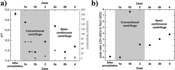 | ||
| Fig. 4 (a) Resulting pH and conductivity values for the cases 1–4. (b). Resulting intensity ratios of LDH (003) to NaCl (002) XRD peaks. | ||
From Fig. 4, it can be seen that the pH and conductivity values hardly drop when the particles are only separated once from the by-products with a batch lab centrifuge (case 1a) but drastically drop when the sample is cleaned in six tedious consecutive washing steps with the lab centrifuge (case 1b). The initial and final XRD-ratios of LDH (003) to NaCl (002) also suggest hardly any cleaning effect for one centrifuge pass but a drastic cleaning effect yielding a nearly NaCl free product after six rounds.
To find out whether it is simply the absolute amount of washing water used that counts to clean the particles, the same dilution factor (deionized water to synthesis product) as cumulatively used in case 1b was set for a single centrifugation pass with a standard laboratory batch centrifuge (case 2). As can be seen from Fig. 4, the product cleanness is quite good but still inferior with respect to cases 1b, particularly with respect to the measure for cleanness from XRD.
In cases 3 and 4, the capabilities of the semi-continuous tubular centrifuge with respect to cleaning an LDH product were exploited.
Case 3a resembles case 1a (only one centrifugation pass). From the cleanness indicators (Fig. 4) it can be seen that without introducing any washing water, the results are pretty similar but slightly better compared to the results, obtained with the batch centrifuge. Case 3b resembles case 2, as also here, a pre-dilution prior to centrifugation was conducted. Again, the purity results are quite comparable to (slightly better than) the batch mode.
To design the process in a more elegant way in order to yield a continuous flow production of clean LDH starting from the reaction and ending with harvesting the final product, case 4 was considered. Here, an additional stream of washing water mixes with the undiluted LDH reaction product directly coming from the static mixer right before entering the centrifuge (see Fig. 2). To compare the efficiency of this approach to case 3, the same amount of water for dilution was used for the same amount of LDH. As can be seen from Fig. 4, the cleanness of the product is nearly equal to case 3 which shows that a fully continuous synthesis and washing cascade can be established.
From these results, it can be concluded, that a continuous synthesis and washing procedure using a tubular centrifuge in a process setup as developed and demonstrated in case 4 is a feasible approach towards producing nano-LDH under steady state conditions, at constant quality and in an acceptably clean form. Also, the potential of product yield already becomes obvious for the small static mixer used in this work: Fig. 5 shows the harvested product of 144 g nano-LDH gel. It was obtained in the cylinder of the centrifuge after 2.5 l of a nano-LDH suspension of a concentration of 30 mg ml−1 passed through the centrifuge at a flow rate of 16.3 l h−1 at a centrifugal rotation speed of 25![[thin space (1/6-em)]](https://www.rsc.org/images/entities/char_2009.gif) 000 rpm for 10 minutes, only.
000 rpm for 10 minutes, only.
 | ||
| Fig. 5 144 g of nano-LDH, harvested from the cylinder (a) of the semi-continuous centrifuge keeping the cylinder body shape as a rigid gel (b). (c) SEM image of the LDH nanoparticles. | ||
The gel can be simply harvested from the cylinder (Fig. 5a) keeping the cylinder body shape as a rigid gel (Fig. 5b) which is composed of the LDH nanoparticles (Fig. 5c).
The obtained gel can be easily redispersed by gentle ultrasonication to the primary particle size. Fig. 6a shows a histogram depicting the particle size distribution (45 ± 20 nm) of a typical sample of nano LDH particles (sample obtained from standard synthesis protocol; see Experimental section 2.1.1), which was obtained from counting 150 particles from SEM images. Fig. 6c shows the size distribution (measured with DLS) of the particles after the gel, harvested from the centrifuge, was redispersed in deionised water. It can be seen that the hydrodynamic diameter of these redispersed particles quite well corresponds to the size of the primary particles as determined from SEM images.
Compared to Fig. 6b, which shows the size distribution of the particles in dispersion right after precipitation before washing (measured with Fraunhofer diffraction), it becomes obvious that the continuous washing process is very effective, as the large agglomerates that occur due to salt presence right after precipitation, could be completely redispersed to the primary particles.
3.2. Varying the reaction conditions via the continuous synthesis process to control the morphology of the nano-LDH
Having established a continuous flow process from reactant reaction to the final clean product with constant conditions throughout all steps and the immediate quenching of the precipitated product, it was possible to study different precipitation conditions with respect to their influence on the LDH nanoparticle morphology. Precipitation syntheses were conducted at 25 °C, however, they were also repeated with precursor solutions priorly heated to 60 °C to ensure that there was no temperature influence on the results.The process established, allows the independent and arbitrary variation of salt concentration (N.B. the ratio of Mg![[thin space (1/6-em)]](https://www.rsc.org/images/entities/char_2009.gif) :
:![[thin space (1/6-em)]](https://www.rsc.org/images/entities/char_2009.gif) Al was always kept constant at 2
Al was always kept constant at 2![[thin space (1/6-em)]](https://www.rsc.org/images/entities/char_2009.gif) :
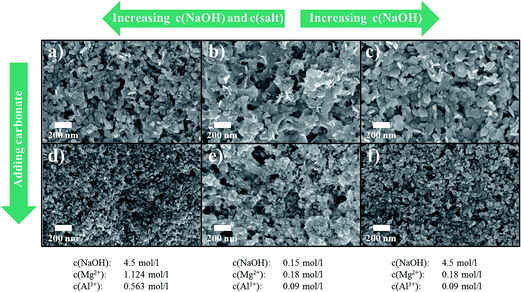
:![[thin space (1/6-em)]](https://www.rsc.org/images/entities/char_2009.gif) 1) and NaOH concentration. This is a crucial difference compared to a batch approach where the conditions change all the time when reactants are added to the batch-vessel (even though the ratio of reactants may stay the same, the overall concentrations in the batch reactor change continuously). Fig. 7 shows SEM images and Fig. 8 the respective XRDs of products, synthesised under different conditions, namely either at high salt and high NaOH concentration (Fig. 7a), at low salt and NaOH concentration (Fig. 7b) or at low salt and high NaOH concentration (Fig. 7c). The 4th case, low NaOH and high salt concentration, did not lead to any precipitation, as expected, for the pH was not high enough in that case.
1) and NaOH concentration. This is a crucial difference compared to a batch approach where the conditions change all the time when reactants are added to the batch-vessel (even though the ratio of reactants may stay the same, the overall concentrations in the batch reactor change continuously). Fig. 7 shows SEM images and Fig. 8 the respective XRDs of products, synthesised under different conditions, namely either at high salt and high NaOH concentration (Fig. 7a), at low salt and NaOH concentration (Fig. 7b) or at low salt and high NaOH concentration (Fig. 7c). The 4th case, low NaOH and high salt concentration, did not lead to any precipitation, as expected, for the pH was not high enough in that case.
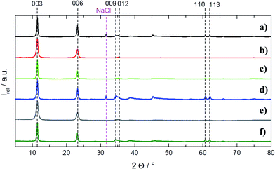 | ||
| Fig. 8 X-ray diffractograms of the samples, depicted in SEM in Fig. 7. The numbering (a–f) corresponds to the equivalent samples as they are depicted in Fig. 7. All XRDs are normalized in intensity with respect to the (003) peak. | ||
It can be seen from the experiments that higher concentrations of both, salt and NaOH, yields slightly more round particles in this continuous process in comparison to the other cases. This can potentially be explained by assuming that a high supersaturation (Fig. 7a) yields a kinetically driven particle formation. The thermodynamically favoured shape of LDH are platelets, i.e., a high aspect ratio of diameter to thickness. However, under a kinetic regime, the precipitation is probably driven by an isotropic growth. The more pronounced growth in c-axis yields for instance a somewhat more pronounced (113) peak in the respective XRD (see Fig. 8a).
Interestingly, repeating the same precipitation conditions but with a deliberate addition of carbonate during precipitation, more spherically shaped particles form in all cases (Fig. 7d–f). As carbonate ideally fits in the interlayers of MgAl (2![[thin space (1/6-em)]](https://www.rsc.org/images/entities/char_2009.gif) :
:![[thin space (1/6-em)]](https://www.rsc.org/images/entities/char_2009.gif) 1) LDH,1,29,30 it probably supports the stacking of Mg and Al along the c-direction of the crystal, i.e., as there is an anion in the interlayers that helps the cations to arrange above it, the growth along the c-direction is supported. The XRDs in Fig. 8d and f also support this assumption as the (113) peak, indicating a proper repetition of the ordering of the cations in the stacked layers, is properly pronounced. However, it also becomes obvious that too low NaOH concentration, i.e., too low pH, hinders the proper crystallization of the structure (XRD Fig. 8e: absence of (113)).
1) LDH,1,29,30 it probably supports the stacking of Mg and Al along the c-direction of the crystal, i.e., as there is an anion in the interlayers that helps the cations to arrange above it, the growth along the c-direction is supported. The XRDs in Fig. 8d and f also support this assumption as the (113) peak, indicating a proper repetition of the ordering of the cations in the stacked layers, is properly pronounced. However, it also becomes obvious that too low NaOH concentration, i.e., too low pH, hinders the proper crystallization of the structure (XRD Fig. 8e: absence of (113)).
It is known from literature that post-treatment of precipitated and washed LDH as aqueous dispersion at elevated temperature for several days leads to recrystallization and therefore a re-ordering of atoms in the LDH crystalline lattice.30
Of course, it depends on the application that is aimed at to choose whether this step is desired/necessary or not. Conducting this step on our samples, we found that the as-precipitated morphology of the LDH, to a certain extent also determines the morphology after recrystallization. This might be highly interesting for applications where the shape of the particles is the most important factor. For instance, more round (spherical) particles might be easier to process in dispersion as they contribute less to a viscosity increase compared to platelets. This might be for instance desired when polymer–LDH composites for flame retardant applications need to be processed.
Platelets with sharp edges, however, are highly anisotropic and might be desired for instance as horizontally aligned fillers in moisture-barrier-coatings.
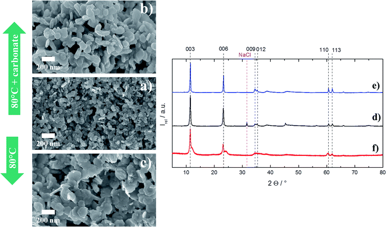
Fig. 9 shows the rather spherically shaped particles that have been obtained from precipitation at very high salt and NaOH concentration in presence of carbonate. It can be seen that the recrystallization (80 °C for 1 week) in either pure deionized water, or in water which contained dissolved carbonate, transformed the shape of the particles to a somewhat more platelet-like. However, the transformation is not very well pronounced and there are no remarkable changes in the XRD either.
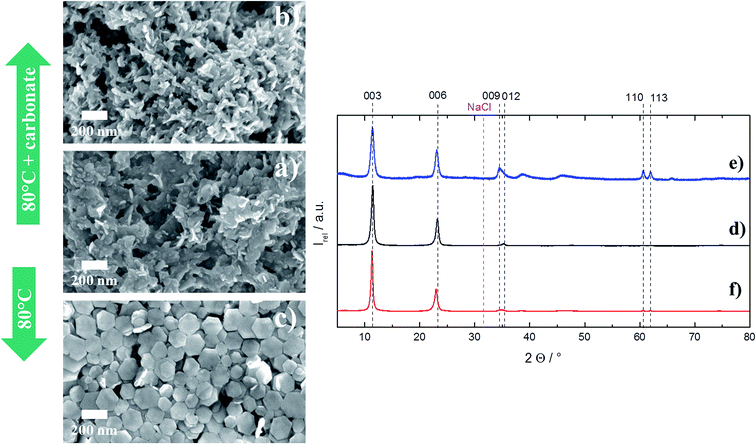
Much more remarkable is the recrystallization behaviour for the particles that have been precipitated at low salt and low NaOH concentration with no carbonate present, i.e. the other extreme compared to the above case (Fig. 10a).
After recrystallization with dissolved carbonate in an aqueous dispersion, a somewhat platelet-like morphology is obtained (Fig. 10b). Without any addition of extra carbonate during recrystallization, perfect hexagonal platelets with very sharp edges form (Fig. 10c). Interestingly, the ordering of the MgAl ions in the stacked layers is poor (XRD, Fig. 10f). That might be explained by a dominated growth in the lateral direction but hardly any growth along the c-direction of the crystal, which again can be attributed to missing carbonate that would be needed for an ordered setup of stacked Mg and Al ions in the subsequent layers.
Thus, depending on the synthesis conditions, two extremes in morphology can be achieved: rather round (spherical) LDH nanoparticles for precipitation conditions of high salt, high NaOH and carbonate presence without recrystallization (see Fig. 7d) and very well defined hexagonal platelets with sharp edges, if precipitation takes place at low salt and NaOH concentration without carbonate presence and a follow-up thermal treatment at 80 °C in deionized, pure water is conducted (see Fig. 10c). These two extremes in morphology also become obvious from TEM images which are depicted in Fig. 11.
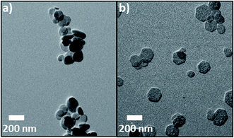 | ||
| Fig. 11 Two distinct morphologies of nano-LDH can be obtained with the process reported herein: (a) rather round shaped particles and (b) well-defined hexagonal platelets with sharp edges. | ||
4. Conclusion
It can be concluded that a combination of continuous precipitation of LDH in static mixers, followed by a down-stream separation and washing in a semi-continuous tubular centrifuge in one go is ideal to obtain LDH at nano size and ensure steady state conditions and an immediately “quenched” precipitation result. By that, it is possible to freely vary the precipitation parameters during synthesis. It was found that the morphology of the particles can be controlled via these parameters to be either round or very well pronounced as hexagonal platelets. The latter can be achieved, with the addition of a recrystallization step after very specific precipitation conditions that need to be carefully chosen beforehand.Acknowledgements
We thank Dr Maurice Mourad very much for the fruitful discussions on the manuscript and his valuable recommendations. We thank Dr Alexander Reinholdt for taking the TEM images. Pavan Muralidhar (Ulm University) is acknowledged for proofreading the manuscript. This project has received funding from the European Union's Horizon 2020 research and innovation programme under grant agreement No. 645993.References
- V. Rives and M. Angeles Ulibarri, Coord. Chem. Rev., 1999, 181(1), 61 CrossRef CAS.
- K. Kuzawa, Y.-J. Jung, Y. Kiso, T. Yamada, M. Nagai and T.-G. Lee, Chemosphere, 2006, 62(1), 45 CrossRef CAS PubMed.
- P. Koilraj and S. Kannan, J. Colloid Interface Sci., 2010, 341(2), 289 CrossRef CAS PubMed.
- H. He, H. Kang, S. Ma, Y. Bai and X. Yang, J. Colloid Interface Sci., 2010, 343(1), 225 CrossRef CAS PubMed.
- R. Chitrakar, S. Tezuka, J. Hosokawa, Y. Makita, A. Sonoda, K. Ooi and T. Hirotsu, J. Colloid Interface Sci., 2010, 349(1), 314 CrossRef CAS PubMed.
- N. Baliarsingh, K. M. Parida and G. C. Pradhan, RSC Adv., 2013, 3(46), 23865 RSC.
- K. Mandel, A. Drenkova-Tuhtan, F. Hutter, C. Gellermann, H. Steinmetz and G. Sextl, J. Mater. Chem. A, 2013, 1(5), 1840 CAS.
- A. Drenkova-Tuhtan, K. Mandel, A. Paulus, C. Meyer, F. Hutter, C. Gellermann, G. Sextl, M. Franzreb and H. Steinmetz, Water Res., 2013, 47(15), 5670 CrossRef CAS PubMed.
- A. Drenkova-Tuhtan, M. Schneider, K. Mandel, C. Meyer, C. Gellermann, G. Sextl and H. Steinmetz, Colloid Surf., A, 2016, 488, 145 CrossRef CAS.
- Q. Wang, Y. Gao, J. Luo, Z. Zhong, A. Borgna, Z. Guo and D. O'Hare, RSC Adv., 2013, 3(10), 3414 RSC.
- Z. Yong and A. E. Rodrigues, Energy Convers. Manage., 2002, 43(14), 1865 CrossRef CAS.
- Q. Wang, Z. Wu, H. H. Tay, L. Chen, Y. Liu, J. Chang, Z. Zhong, J. Luo and A. Borgna, Catal. Today, 2011, 164(1), 198 CrossRef CAS.
- Q. Wang, H. H. Tay, Z. Zhong, J. Luo and A. Borgna, Energy Environ. Sci., 2012, 5(6), 7526 CAS.
- Q. Wang, J. Luo, Z. Zhong and A. Borgna, Energy Environ. Sci., 2011, 4(1), 42 CAS.
- S. Choi, J. H. Drese and C. W. Jones, ChemSusChem, 2009, 2(9), 796 CrossRef CAS PubMed.
- A. C. S. Alcântara, P. Aranda, M. Darder and E. Ruiz-Hitzky, J. Mater. Chem., 2010, 20(42), 9495 RSC.
- V. Ambrogi, G. Fardella, G. Grandolini and L. Perioli, Int. J. Pharm., 2001, 220(1–2), 23 CrossRef CAS PubMed.
- C. R. Gordijo, C. A. Barbosa, A. M. Da Costa Ferreira, V. R. Constantino and D. de Oliveira Silva, J. Pharm. Sci., 2005, 94(5), 1135 CrossRef CAS PubMed.
- B. Li, J. He, D. G. Evans and X. Duan, Int. J. Pharm., 2004, 287(1–2), 89 CrossRef CAS PubMed.
- M. Del Arco, E. Cebadera, S. Gutiérrez, C. Martín, M. J. Montero, V. Rives, J. Rocha and M. A. Sevilla, J. Pharm. Sci., 2004, 93(6), 1649 CrossRef CAS PubMed.
- C. Ribeiro, G. G. C. Arizaga, F. Wypych and M.-R. Sierakowski, Int. J. Pharm., 2009, 367(1–2), 204 CrossRef CAS PubMed.
- J. Wang, L. Wang, X. Chen, Y. Lu and W. Yang, J. Solid State Electrochem., 2015, 19(7), 1933 CrossRef CAS.
- Y. Gao, J. Wu, Q. Wang, C. A. Wilkie and D. O'Hare, J. Mater. Chem. A, 2014, 2(29), 10996 CAS.
- Z. Matusinovic and C. A. Wilkie, J. Mater. Chem., 2012, 22(36), 18701 RSC.
- Y. Feng, P. Tang, J. Xi, Y. Jiang and D. Li, Recent Pat. Nanotechnol., 2012, 6(3), 231 CrossRef CAS PubMed.
- X. Guo, F. Zhang, D. G. Evans and X. Duan, Chem. Commun., 2010, 46(29), 5197 RSC.
- Z. Chang, D. G. Evans, X. Duan, C. Vial, J. Ghanbaja, V. Prevot, M. de Roy and C. Forano, J. Solid State Chem., 2005, 178(9), 2766 CrossRef CAS.
- Q. Wang, S. V. Y. Tang, E. Lester and D. O'Hare, Nanoscale, 2013, 5(1), 114 RSC.
- T. Sato, H. Fujita, T. Endo and M. Shimada, React. Solids, 1988, 5, 219 CrossRef CAS.
- T. Stanimirova and G. Kirov, Appl. Clay Sci., 2003, 22(6), 295 CrossRef CAS.
| This journal is © The Royal Society of Chemistry 2016 |


