
 Open Access Article
 This Open Access Article is licensed under a Creative Commons Attribution-Non Commercial 3.0 Unported Licence
Structure determination of organic aging products in lithium-ion battery electrolytes with gas chromatography chemical ionization mass spectrometry (GC-CI-MS)†
Martin
Grützke
,
Waldemar
Weber
,
Martin
Winter
and
Sascha
Nowak
*
University of Münster, MEET Battery Research Center, Institute of Physical Chemistry, Corrensstrasse 46, 48149 Münster, Germany. E-mail: sascha.nowak@uni-muenster.de; Fax: +49 251 83 36032; Tel: +49 251 83 36735
First published on 10th June 2016
Abstract
For Gas Chromatography Chemical Ionization Mass Spectrometry (GC-CI-MS) method development, a standard lithium-ion battery (LIB) electrolyte was thermally aged at 95 °C for a faster generation of decomposition products. Interestingly, phosphorous containing aging products were preferably formed in the first hours. Furthermore, the organic containing aging products without phosphorous are formed after longer times. Since, these compounds are very similar in structure, molecular mass and consequently in their fragmentation during electron ionization (EI) experiments, chemical ionization was applied to identify the structure of the LIB electrolyte aging products. Herein, the results of the structure determination of organic LIB electrolyte aging products with GC-CI-MS are presented. Furthermore, formation of the identified species and relative concentrations over a time period of 22 days were determined by using an internal standard.
1. Introduction
Lithium-ion batteries (LIBs) are the foundation of modern consumer electronics and portable devices. Furthermore, these energy storage systems are the most promising technology for electric and hybrid electric vehicles. Unfortunately, the lifetime of LIBs is limited due to electrochemical, thermal and calendric aging.1 State of the art electrolytes for LIBs usually consist of LiPF6 as a conducting salt dissolved in a mixture of different linear and cyclic organic carbonates, e.g. ethyl methyl carbonate (EMC) and ethylene carbonate (EC).20 Despite the chemical and thermal instability in organic carbonates towards the P–F bond, LiPF6 is the most commercial applied conducting salt today.2,3 In comparison to other applied salts, lithium hexafluorophosphate still has several advantages like high solubility in organic carbonates, high electrochemical stability and excellent solid electrolyte interphase (SEI) forming capabilities.4–6 However, due to its thermal instability, hexafluorophosphate undergoes the decomposition to highly reactive PF5. As a consequence, numerous decomposition products are formed in LIB electrolytes and are an ongoing subject of investigations with different methods. The variety of decomposition products ranges from HF,7–10,25 inorganic and organic phosphates (OPs),11–19,26 CO2,21,22 over dicarboxylates,23,24 diols8 and alkyl fluorides.9,12,21 Furthermore, the applied methods and corresponding reaction mechanisms are intensively discussed in the literature.13–18,27–40One particular interesting group is the group of ethylene bridged carbonates and oligomeric alkoxy ethylene glycols. However, the clear identification of these compounds only with gas chromatography hyphenated to mass spectrometry (GC-MS) is challenging due to many compounds with identical molecular masses and very similar spectra obtained with electron ionization (EI). Structure determination has been performed by Gireaud et al.27 and Gachot et al.28 However, both used electrospray ionization (ESI)-HRMS based techniques. Within this work it was demonstrated, that sophisticated HRMS experiments are not mandatory and structure determination can be carried out by performing GC-MS with chemical ionization experiments without the need of another technique. To proof this approach, a standard electrolyte was thermally aged at 95 °C for a faster generation of decomposition products as sample for GC-CI-MS method development. The thermal electrolyte aging leads to the same aging products as electrochemical aging and can therefore carried out in this manner.8,13,14,27,28,30,35,37 Besides dimethyl-2,5-dioxahexane dicarboxylate (DMDOHC), ethyl methyl-2,5-dioxahexane dicarboxylate (EMDOHC) and diethyl-2,5-dioxahexane dicarboxylate (DEDOHC), clear structure determination of several other LIB electrolyte aging products was achieved with GC-CI-MS. Interestingly, phosphorous containing aging products were preferably formed in the first hours. Nevertheless, the results of their structure determination after aging of 48 hours have recently been published by Weber et al.15 Organic containing aging products without phosphorous are formed after longer times of thermal treatment. Herein, the results of the structure determination of organic LIB electrolyte aging products with GC-CI-MS for the same sample after aging of several weeks are presented. Furthermore, formation of the identified species and relative concentrations over a time period of 22 days were determined by using an internal standard (IS). The identified compounds which are presented in this work are the result of aging reactions of the different constituents of the electrolyte solvent with each other.
2. Experimental
2.1 Chemicals and materials
LP50 (EMC/EC, 1 mol L−1 LiPF6, battery grade) from BASF and dichloromethane (99.9%) from VWR were used. Tris(2,2,2-trifluoroethyl) phosphate (pure according to NMR) which was used as IS was synthesized in the working group of Prof. Dr Gerd-Volker Röschenthaler at the Jacobs University of Bremen. The GC was run with helium (purity 6.0) as carrier gas and NH3 (purity 3.8) for CI experiments, both purchased from Westfalen Gas.2.2 Sample preparation
2 mL of the LP50 electrolyte were thermally aged for 22 days at 95 °C in 10 mL aluminum vials with butyl/PTFE caps. After certain times, 25 μL of the sample were transferred into a 2 mL PP Safe-Lock tube, spiked with 5 μL IS and diluted with 1 mL dichloromethane. After centrifugation at 8500 rpm for 5 minutes, the clear solution was investigated with GC-MS without the centrifuged solid LiPF6. Independent samples were used for each data point in the time depending investigations.2.3 GC-CI-MS setup
GC-MS experiments were carried out on a Shimadzu GCMS-QP2010 Ultra equipped with an AOC-5000 Plus autosampler and an OPTIC-4 injection system. GCMS Real Time Analysis and GCMS Postrun Analysis were used for setup control and data analysis. The OPTIC-4 injector was controlled and monitored with the Evolution Workstation software. EI, PCI and NCI were measured with a combined ion source. NH3 (introduced with 3 bar) was used for CI experiments. 1 μL of the diluted samples was injected at an injection temperature of 230 °C onto a Restek Rxi-5ms column (30 m × 0.25 mm × 0.25 μm) with a deactivated guard-column (5 m × 0.25 mm). The system was run with helium as carrier gas with a column flow of 1 mL min−1, a split of 1![[thin space (1/6-em)]](https://www.rsc.org/images/entities/char_2009.gif) :10 and the following column oven program: starting with 40 °C for 1 min, the temperature was increased with a rate of 3 °C min−1 to 60 °C and then with 30 °C min−1 to 230 °C. It was measured in a range of m/z = 30–400 with an event time of 0.1 s at an interface temperature of 250 °C, an ion source temperature of 200 °C, a filament voltage of 70 V and a detector voltage which was chosen relative to the current tuning result. An additional injector and column with a flow of 0.6 mL min−1 was connected via a T-fitting with the used column to the same MS-detector. Thus, the absolute column flow at the MS entrance was 1.6 mL min−1.
:10 and the following column oven program: starting with 40 °C for 1 min, the temperature was increased with a rate of 3 °C min−1 to 60 °C and then with 30 °C min−1 to 230 °C. It was measured in a range of m/z = 30–400 with an event time of 0.1 s at an interface temperature of 250 °C, an ion source temperature of 200 °C, a filament voltage of 70 V and a detector voltage which was chosen relative to the current tuning result. An additional injector and column with a flow of 0.6 mL min−1 was connected via a T-fitting with the used column to the same MS-detector. Thus, the absolute column flow at the MS entrance was 1.6 mL min−1.
For the time depending GC-MS experiments a Perkin Elmer GC-MS Clarus 600 with a polar Restek Stabilwax column (30 m × 0.25 mm × 0.25 μm) was used. TurboMass 5.4.2 and Clarity software were used for setup control and data analysis. The injection temperature was 210 °C. The column flow was 1 mL min−1 with the same split, column and column oven program as just described above. The mass spectrometer was run with a detector voltage of 1.5 kV. Masses were recorded between m/z = 30–350. The following specific fragments were used in SIM mode for relative concentration monitoring over time: IS (115 m/z), 6 (72 m/z), 8 (74 m/z), 11 (104 m/z), 12 (89 m/z), 14 (103 m/z), 15 (91 m/z), 17 (91 m/z), 18 (103 m/z), 22 (103 m/z), 23 (148 m/z), 26 (103 m/z) and 27 (117 m/z).
3. Results and discussion
The thermally aged electrolyte was analyzed with GC-MS. The chromatogram measured with the EI setup is presented in Fig. 1. | ||
| Fig. 1 (a) Chromatogram (GC-MS) of LP50 electrolyte (EMC/EC, 1 mol L−1 LiPF6), which was thermally aged for 22 days at 95 °C in gas-tight aluminum vials. The figures below (b–d) show the enlarged regions of interest, (b–d) enlargement for the regions 0–5 min (b), 10–11 min (c) and 11–12.5 min (d). | ||
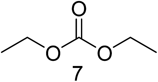
A complex mixture of 28 compounds was separated with the applied method. In most cases, baseline separation could be achieved. Peaks 1, 3, 7 and 13 were assigned to DMC, EMC, DEC and EC. EMC and EC were used in the investigated electrolyte. At a retention time of around 10 minutes, the detector voltage was decreased to 0.7 kV to improve the observability of the following compounds. Thus, the EC peak is not as sharp as in GC standard chromatograms. DMC and DEC are formed during aging in a trans-esterification reaction of EMC.34 For each of these four organic carbonates with different molecular masses, at least one other substance with the same mass could be observed in the thermally aged electrolyte of Fig. 1. Table 1 summarizes this substance group, whose compounds elute within the first six minutes.
| M = 88 | M = 90 | M = 104 | M = 118 |
|---|---|---|---|

|

|
|
|

|

|

|

|
|
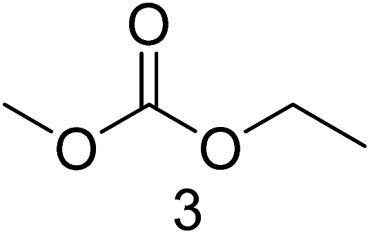
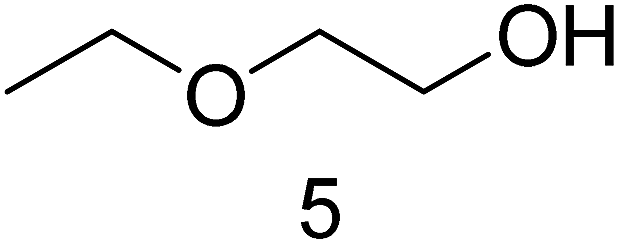
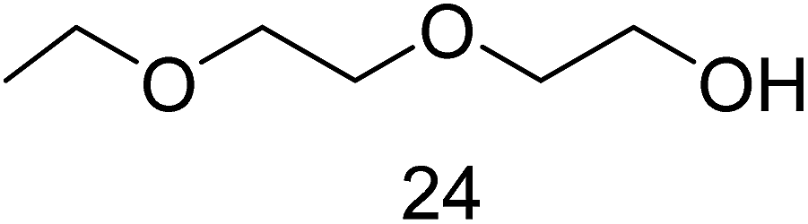
Structure determination for compounds 2, 4, 5 and 8 was achieved by comparison of the measured EI spectra with the NIST 08 library. The EI spectrum of compound 6 did not match with an appropriate EI spectrum of this library. Thus, GC-CI-MS experiments with the same equipment and method were carried out. The (M + H)+ and (M + NH4)+ signals of the PCI spectra for compound 6 resulted in a molecular mass of 104. In combination with the three significant signals in the NCI spectrum (Fig. 2), which are 31 m/z for CH3O−, 45 m/z for CH3CH2O− and 75 m/z for CH3OCH2CH2O−, only the structure of 1-ethoxy-2-methoxy ethane is possible. EMC for example has the same molecular mass of 104 but different negative fragments. The binding energy of the C–O bond in the CO3 structure element is stronger compared to the C–O bond in the R–O–R structure element of compound 6, benefited by mesomeric effects. Thus, the observed significant negative fragments for EMC are 75 m/z for CH3CO3− and 89 m/z for CH3CH2CO3− (Fig. 3). Furthermore, PCI and NCI data for the already identified compounds 2, 4, 5 and 8 confirmed the results which were obtained by comparison of the EI spectra with NIST 08 (all additional EI, PCI and NCI spectra are presented in the ESI Table†).
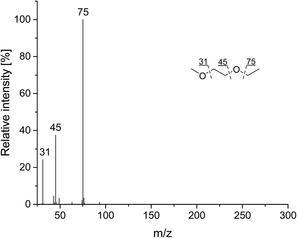 | ||
| Fig. 2 NCI spectrum of 1-ethoxy-2-methoxy ethane (compound 6, Table 1) including the corresponding stable fragments with fragmentation pattern. | ||
 | ||
| Fig. 3 NCI spectrum of EMC (compound 3, Table 1) including the corresponding stable fragments with fragmentation pattern. | ||
Compounds 9, 10, 19 and 20 in the chromatogram of Fig. 1 are fluoro alkyl phosphates. The structures are presented in Fig. 4.
 | ||
| Fig. 4 Structures of detected fluoro alkyl phosphates corresponding to Fig. 1. | ||
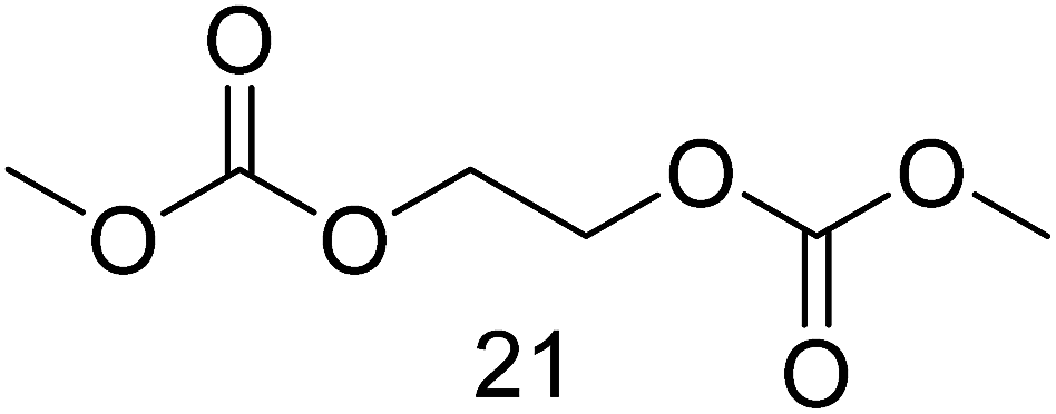
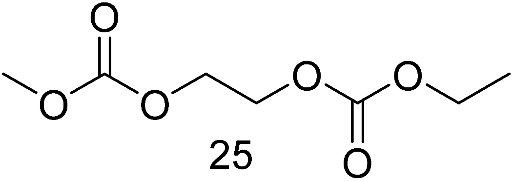
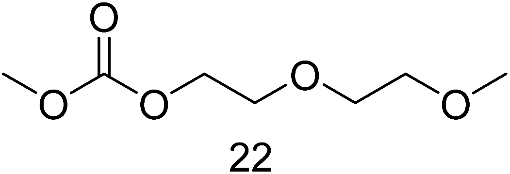
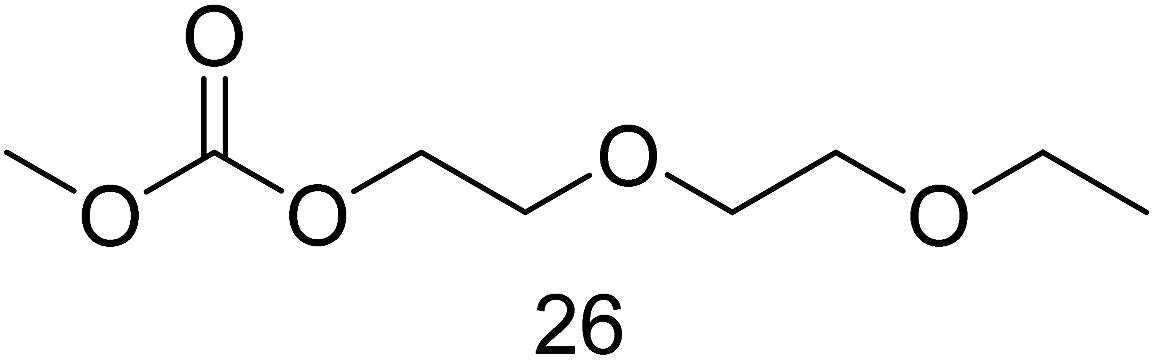
Compounds 12 and 18 were also identified with the NIST 08 library. The remaining analytes of Fig. 1 were studied in the same manner than compound 6 because reference spectra were not available. The combination of EI, PCI and NCI spectra (presented in the ESI Table†) led to the structures presented in Table 2. Very similar EI spectra and many similar molecular masses made it challenging but NCI gave doubtless evidence about the structures due to significant negative fragments as exemplarily described for compound 6. Furthermore, the retention times differ based on the size and the polarity of the compounds. On the applied non-polar column, small analytes elute first. Moreover, compounds with the organic carbonate structure always elute before the ethylene oxide derivatives. A terminal methyl group leads to a shorter retention time than terminal ethyl groups. The same behavior was observed for a terminal methyl group at the carbonate site compared to the ethylene oxide site. The ratios of the (M + H)+ and (M + NH4)+ signals can also be taken into account while determining such structures. A decreasing amount of carbonate functional groups in the compound at the same molecular mass and thus more ethylene oxide groups leads to more (M + H)+ intensity relative to the (M + NH4)+ signal. The same behavior occurs with terminal ethyl groups instead of terminal methyl groups.
| M = 134 | M = 148 | M = 162 | M = 178 | M = 192 |
|---|---|---|---|---|

|

|
|
|
|
|
|
|||

|

|

|
||

|

|

|

|

|
|
The two fragments of 77 m/z and 91 m/z, respectively, could also be determined as clear structure indicators in the EI spectra from the chromatogram in Fig. 1 which contain an organic carbonate functional group with either a terminal methyl or a terminal ethyl group. Wherever possible, formation of the organic aging products was monitored over time. A period of 22 days was investigated. Therefore, an IS [tris(2,2,2-trifluoroethyl) phosphate] was added to the electrolyte solution before each measurement. A separate vial with electrolyte and IS was prepared for each data point. The formed substances can be categorized in three different groups: group one (G1) is consisting of compounds with two organic carbonate functional groups within one molecule. It was not possible to monitor their formation behavior over time due to not completely baseline separated peaks (see compounds 21–28 in Fig. 1). Although, the investigations were carried out with single ion monitoring of compound specific fragments, some peaks are still overlapping due to the almost identical fragmentation of the investigated aging products caused by similar molecular structures. Baseline separation of G1 would have been possible in principal but at the expense of much longer measurement times. However, different equipment (such as 2D GC) which were not available for these experiments would also lead to the intended separation. Additionally, method development with regards to short measurement times at simultaneous baseline separation would be challenging for such approaches as well.
Group two (G2) consists of molecules with a carbonate functional group as well as an ethylene glycol functional group. Their formation behavior over time is presented in Fig. 5a. Fig. 5b depicts the results for the third group (G3) which is composed of substances with oligomeric ethylene glycol chains only. All three groups can be categorized further depending on the substitution pattern of methyl or ethyl groups at their terminals.
 | ||
| Fig. 5 Formation behavior of organic aging products (a: group 2; b: group 3) over time. Peak area ratios are calculated based on tris(2,2,2-trifluoroethyl) phosphate as internal standard. All ratios are normed on the highest value after 22 days for better comparability. Thus, the ratios have to be understood as tendencies and not as absolute values. | ||
Compared to G3, it can be observed that G2 is formed first, starting already after a few days of thermal aging. Especially compounds 11, 14, 15 and 17 are formed quickly. Compared to the other three substances in G2, they show one ethylene glycol group less. The longer the ethylene glycol chain, the more time is needed for their formation. This leads to the conclusion that the longer chained molecules are formed from the shorter ones which is in good agreement to the formation mechanisms stated in literature. Furthermore, G3 compounds which are consisting of ethylene glycol chains only, without organic carbonate functional groups at all, are formed after most of the G2 molecules. The reason is the same as just discussed. For their formation which starts most likely after 13 days, the corresponding compounds from G2 need to be present in the solution in sufficient amounts moreover, it seems that the concentrations for 11, 14, 15 and 17 are running into a limit after 20 days because they are also consumed. The curve shape in Fig. 5a shows a sigmoidal character. Their formation and consumption to longer chained compounds reaches a steady state. Approximately the same amounts are formed and consumed simultaneously.
4. Conclusions
A standard LIB electrolyte (EMC/EC, 1 mol L−1 LiPF6) was thermally aged at 95 °C for 22 days and used for method development to detect organic aging products with GC-CI-MS. A complex chromatogram of 28 compounds was obtained. The compounds are very similar in structure, molecular masses and consequently in their fragmentation during EI experiments. The GC method was optimized regarding separation and time. The majority of the obtained peaks could be baseline separated within a measurement time of 12 minutes. Clear structure determination of every compound could be achieved based on the combination of EI with PCI and NCI spectra. The intensity ratios of (M + H)+ and (M + NH4)+ are furthermore significant structure indicators for this compound family and can be combined with specific fragments of EI, PCI and NCI spectra. After successful identification of the related compounds, the obtained spectra can be used as data base for library search in future aging investigations, which should also include electrochemical experiments to investigate the influence on the occurring reactions. Furthermore, the formation of the aging products was monitored over time. Therefore, samples were investigated in certain time intervals. Relative concentrations were referenced to an IS. Compounds of G2 are formed first compared to G3. Moreover, the shorter molecules of G2 (11, 14, 15 and 17) are already formed in detectable quantities after a few days whereas formation of the other substances in significant amounts takes almost two weeks. Likewise, the longer chained molecules are being formed by the shorter ones which is also proven by the sigmoidal curve shapes.In comparison to organophosphates, formation of the organic aging products takes more time. The relative quantification with the IS led to the conclusion, that G1–G3 are present in much higher concentrations after 22 days compared to the P containing compounds. This behavior should be investigated further during electrochemical aging because some fluoro alkyl phosphates which belong to this substance class are highly toxic41–44 and information about their concentrations in real LIB cells or their preferred formation under certain conditions are therefore required.
Acknowledgements
We kindly thank the Federal Ministry for the Environment, Nature Conservation and Nuclear Safety for funding of the project LithoRec II (project grant number: 16EM1025).References
- J. Vetter, P. Novák, M. R. Wagner, C. Veit, K. C. Möller, J. O. Besenhard, M. Winter, M. Wohlfahrt-Mehrens, C. Vogler and A. Hammouche, J. Power Sources, 2005, 147, 269–281 CrossRef CAS.
- K. Xu, Chem. Rev., 2004, 104, 4303–4418 CrossRef CAS PubMed.
- K. Xu, Chem. Rev., 2014, 114, 115503–115618 CrossRef PubMed.
- V. Aravindan, J. Gnanaraj, S. Madhavi and H.-K. Liu, Chem.–Eur. J., 2011, 17, 14326–14346 CrossRef CAS PubMed.
- M. Ue and S. Mori, J. Electrochem. Soc., 1995, 142, 2577–2581 CrossRef CAS.
- M. Ue, J. Electrochem. Soc., 1994, 141, 3336–3342 CrossRef CAS.
- S. F. Lux, J. Chevalier, I. T. Lucas and R. Kostecki, ECS Electrochem. Lett., 2013, 242, A121–A123 CrossRef.
- L. Terborg, S. Weber, F. Blaske, S. Passerini, M. Winter, U. Karst and S. Nowak, J. Power Sources, 2013, 242, 832–837 CrossRef CAS.
- P. Handel, G. Fauler, K. Kapper, M. Schmuck, C. Stangl, R. Fischer, F. Uhlig and S. Koller, J. Power Sources, 2014, 267, 255–259 CrossRef CAS.
- H. Yang, G. V. Zhuang and P. N. Ross Jr, J. Power Sources, 2006, 161, 573–579 CrossRef CAS.
- C. L. Campion, W. Li, W. B. Euler, B. L. Lucht, B. Ravdel, J. F. DiCarlo, R. Gitzendanner and K. M. Abraham, Electrochem. Solid-State Lett., 2004, 7, A194–A197 CrossRef CAS.
- C. L. Campion, W. Li and B. L. Lucht, J. Electrochem. Soc., 2005, 152, A2327–A2334 CrossRef CAS.
- V. Kraft, M. Grützke, W. Weber, M. Winter and S. Nowak, J. Chromatogr. A, 2014, 1354, 92–100 CrossRef CAS PubMed.
- B. Vortmann, S. Nowak and C. Engelhard, Anal. Chem., 2013, 85, 3433–3438 CrossRef CAS PubMed.
- W. Weber, V. Kraft, M. Grützke, M. Winter and S. Nowak, J. Chromatogr. A, 2015, 1394, 128–136 CrossRef CAS PubMed.
- M. Grützke, V. Kraft, B. Hoffmann, S. Klamor, J. Diekmann, A. Kwade, M. Winter and S. Nowak, J. Power Sources, 2015, 273, 83–88 CrossRef.
- V. Kraft, W. Weber, B. Streipert, R. Wagner, C. Schultz, M. Winter and S. Nowak, RSC Adv., 2016, 6, 8–17 RSC.
- W. Weber, R. Wagner, B. Streipert, V. Kraft, M. Winter and S. Nowak, J. Power Sources, 2016, 306, 193–199 CrossRef CAS.
- V. Kraft, W. Weber, M. Grützke, M. Winter and S. Nowak, RSC Adv., 2015, 5, 80150–80157 RSC.
- J. Barthel and H. J. Gores, Handbook of Battery Materials, Wiley-VCH, Weinheim, 1999 Search PubMed.
- G. Gachot, P. Ribieère, D. Mathiron, S. Grugeon, M. Armand, J.-B. Leriche, S. Pilard and S. Laruelle, Anal. Chem., 2011, 83, 478–485 CrossRef CAS PubMed.
- B. Ravdel, K. M. Abraham, R. Gitzendanner, J. DiCarlo, B. Lucht and C. Campion, J. Power Sources, 2003, 119–121, 805–810 CrossRef CAS.
- M. Grützke, V. Kraft, W. Weber, C. Wendt, A. Friesen, S. Klamor, M. Winter and S. Nowak, J. Supercrit. Fluids, 2014, 94, 216–222 CrossRef.
- M. Grützke, X. Mönnighoff, F. Horsthemke, V. Kraft, M. Winter and S. Nowak, RSC Adv., 2015, 5, 43209–43217 RSC.
- L. Terborg, S. Nowak, S. Passerini, M. Winter, U. Karst, P. R. Haddad and P. N. Nesterenko, Anal. Chim. Acta, 2012, 714, 121–126 CrossRef CAS PubMed.
- M. Grützke, S. Krüger, V. Kraft, B. Vortmann, S. Rothermel, M. Winter and S. Nowak, ChemSusChem, 2015, 8, 3433–3438 CrossRef PubMed.
- L. Gireaud, S. Grugeon, S. Pilard, P. Guenot, J.-M. Tarascon and S. Laruelle, Anal. Chem., 2006, 78, 3688–3698 CrossRef CAS PubMed.
- G. Gachot, S. Grugeon, M. Armand, S. Pilard, P. Guenot, J.-M. Tarascon and S. Laruelle, J. Power Sources, 2008, 178, 409–421 CrossRef CAS.
- S. E. Sloop, J. K. Pugh, S. Wang, J. B. Kerr and K. Kinoshita, Electrochem. Solid-State Lett., 2001, 4, A42–A44 CrossRef CAS.
- V. Kraft, M. Grützke, W. Weber, J. Menzel, S. Wiemers-Meyer, M. Winter and S. Nowak, J. Chromatogr. A, 2015, 1409, 201–209 CrossRef CAS PubMed.
- K. Tasaki, K. Kanda, S. Nakamura and M. Ue, J. Electrochem. Soc., 2003, 150, A1628–A1636 CrossRef CAS.
- M. Broussely, P. Biensan, F. Bonhomme, P. Blanchard, S. Herreyre, K. Nechev and R. J. Staniewicz, J. Power Sources, 2005, 146, 90–96 CrossRef CAS.
- T. Kawamura, S. Okada and J.-I. Yamaki, J. Power Sources, 2006, 156, 547–554 CrossRef CAS.
- H. Yoshida, T. Fukunaga, T. Hazama, M. Terasaki, M. Mizutani and M. Yamachi, J. Power Sources, 1997, 68, 311–315 CrossRef CAS.
- T. Sasaki, T. Abe, Y. Iriyama, M. Inaba and Z. Ogumi, J. Power Sources, 2005, 150, 208–215 CrossRef CAS.
- T. Sasaki, T. Abe, Y. Iriyama, M. Inaba and Z. Ogumi, J. Electrochem. Soc., 2005, 152, A2046–A2050 CrossRef CAS.
- C. Schultz, V. Kraft, M. Pyschik, S. Weber, F. Schappacher, M. Winter and S. Nowak, J. Electrochem. Soc., 2015, 162, A629–A634 CrossRef CAS.
- G. E. Blomgren, J. Power Sources, 1999, 81–82, 112–118 CrossRef CAS.
- U. Heider, R. Oesten and M. Jungnitz, J. Power Sources, 1999, 81–82, 119–122 CrossRef CAS.
- X. Zhang, P. N. Ross, R. Kostecki, F. Kong, S. Sloop, J. B. Kerr, K. Striebel, E. J. Cairns and F. McLarnon, J. Electrochem. Soc., 2001, 148, A463–A470 CrossRef CAS.
- F. M. Raushel, Nature, 2011, 469, 310–311 CrossRef CAS PubMed.
- http://www.lookchem.com, referenced to Journal of Toxicology and Environmental Health, 1989, 26, 437.
- http://www.lookchem.com, referenced to Deutsche Gesundheitswesen, 1960, 15, 2179.
- S. D. Silver, J. Ind. Hyg. Toxicol., 1948, 30, 307–311 CAS.
Footnote |
| † Electronic supplementary information (ESI) available. See DOI: 10.1039/c6ra09323j |
| This journal is © The Royal Society of Chemistry 2016 |