Panchromatic engineering for efficient zinc oxide flexible dye-sensitized solar cells using porphyrin and indoline dyes

Yu-Kai Syua, Yogesh Tingareb, Chen-Yu Yeh*b, Jih-Sheng Yanga and Jih-Jen Wu*a
aDepartment of Chemical Engineering, National Cheng Kung University, Tainan, 701, Taiwan. E-mail: wujj@mail.ncku.edu.tw
bDepartment of Chemistry and Research Center for Sustainable Energy and Nanotechnology, National Chung Hsing University, Taichung, 402, Taiwan. E-mail: cyyeh@dragon.nchu.edu.tw

Received 11th April 2016 , Accepted 11th June 2016

First published on 15th June 2016


Abstract

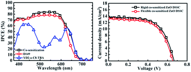
In this work, panchromatic engineering of room temperature (RT) chemically assembled ZnO anodes has been investigated using low acidity porphyrin and indoline dyes, i.e. YD2-o-C8-TBA and D149, for application in flexible dye-sensitized solar cells (DSSCs). The photovoltaic performance of the YD2-o-C8-TBA/D149 co-sensitized ZnO DSSC was optimized using ZnO anodes prepared on indium tin oxide (ITO)-coated glass substrates. The short-circuit current density of the optimized co-sensitized ZnO DSSC is 10% and 75% higher than those of the individual D149-sensitized and YD2-o-C8-TBA-sensitized cells, respectively. Compared to the D149-sensitized cell, the YD2-o-C8-TBA/D149 co-sensitized ZnO DSSC with a wavelength ranging from 475–700 nm exhibited improved photon-to-current conversion efficiencies. The optimized cell efficiency of 5.6% is accounted for by the rigid co-sensitized ZnO DSSC. Due to the RT fabrication of the ZnO anode, a comparable photovoltaic performance is attained with the co-sensitized ZnO DSSC fabricated using the ITO-coated plastic substrates. An efficiency of 5.3% is monitored in the flexible co-sensitized ZnO DSSC.


Introduction

Dye-sensitized solar cells (DSSCs), which feature a low cost and a relatively high efficiency, have attracted considerable interests since a breakthrough of TiO2-based DSSCs reported by O’Regan and Grätzel in 1991.1 Particularly, flexible and light-weight DSSCs are promising solar cells that can meet the requirements of renewable and mobile power sources for portable electronic devices.2 However, the fabrication of high efficiency TiO2-based DSSCs on plastic transparent conducting substrates is still a challenge. Most plastic substrates show limited temperature sustainability up to ∼150 °C whereas for the construction of expedient electron transport pathways, which is crucial for achieving an efficient DSSC, thermal treatment of the TiO2 mesoporous anodes at an elevated temperature is needed.1,3 Due to its high electron mobility and low crystallization temperature, ZnO has been demonstrated to be a very promising candidate for a flexible DSSC anode.3–5 On the other hand, the deterioration of ZnO-based anodes during the dye soaking process resulting from the poor chemical stability of ZnO in acidic dye solution6 limits the performance of ZnO-based DSSCs.

Metal-free organic indoline dyes with relatively lower acidity show a comparatively good match with ZnO.7–11 An efficiency higher than 5% for flexible ZnO-based DSSCs has been achieved using the indoline dye coded D149.4,5 The main absorption of D149 adsorbed on ZnO is in the range of 400–600 nm with a tail extended to ∼650 nm. Although D149 exhibits high extinction coefficients, the performance of the D149-sensitized ZnO solar cells is also restricted by the narrow absorption range.

It is very demanding to synthesize a dye with a broad absorption spectrum and appropriate energy levels for panchromatic DSSCs.12 Substantial efforts have been made to extend the absorption threshold wavelength for the panchromatic engineering of rigid TiO2-based DSSCs through co-sensitization methods in which multi-dyes with complementary absorption spectra are utilized.13–16 Remarkable efficiencies of 11–14% have been achieved through co-sensitized DSSCs.13,15,16 However in co-sensitization, the intermolecular interactions between the dyes may also lead to a decrease in the DSSC efficiency.12

Porphyrin dyes have been widely used in DSSCs due to their strong absorbing bands in a wide wavelength range covering the visible to the near-IR region.13–15,17–21 Except for the region around 500 nm, porphyrin dyes show a strong Soret band (400–450 nm) and a moderate Q band (550–600 nm) with remarkably high molecular absorption coefficients up to 105 M−1 cm−1 in the visible region of 400–700 nm.15 In the case of rigid TiO2-based DSSCs, an efficiency of 11.9% was reported in a zinc porphyrin (YD2-o-C8)-sensitized DSSC with cobalt-based electrolyte.13 The co-sensitization of zinc porphyrin with an organic dye achieved efficiencies of 12.3% and 11.5% using cobalt-based electrolyte13 and iodine electrolyte,15 respectively. Comparatively, very low efficiencies (≤0.5%) were reported for the porphyrin-sensitized ZnO-based DSSCs.22,23 Jensen et al. synthesized 5-(5,15-bis(2,6-di(n-hexoxy)phenyl)porphyrinato zinc(II)-2-yl)-2-carboxypenta-2,4-dienoic acid to sensitize ZnO nanotube electrodes.22 These electrodes showed a 0.5% DSSC efficiency. Sarkar et al. fabricated hematoporphyrin-sensitized ZnO nanorod photoanodes and achieved an efficiency of 0.2% in the hematoporphyrin–ZnO nanohybrid DSSC.23

We have demonstrated a room temperature (RT) chemically assembled ZnO aggregated anode on indium tin oxide (ITO)-coated polyethylene terephthalate (PET) for flexible DSSCs.5 The anode was composed of a drop-cast ZnO nanoparticle (NP) film interconnected by the RT-grown nanostructures after RT chemical bath deposition. With a light-scattering ZnO particle layer prepared on the top using the same approach, an efficiency of 5.16% was achieved in the flexible D149-sensitized ZnO DSSC.5 In this work, co-sensitization of the flexible ZnO anode with D149 and porphyrin dyes was investigated to further improve the performance of the flexible ZnO-based DSSCs. In order to reduce the acidity of the porphyrin dye, YD2-o-C8-TBA dye was prepared by replacing a proton in the carboxyl group of the YD2-o-C8 dye with tetrabutyl ammonium (TBA+). An efficiency larger than 2% was attained in the YD2-o-C8-TBA-sensitized ZnO DSSC. Moreover, an optimized efficiency of 5.62% is measured in the rigid co-sensitized ZnO DSSC. As the ZnO anodes are chemically assembled at RT without high temperature post-treatment and mechanical compression,5 comparable photovoltaic performances are attained in both flexible and rigid co-sensitized ZnO DSSCs. An efficiency of 5.29% is monitored in the flexible co-sensitized ZnO DSSC.

Experimental

The details for the fabrication of the RT chemically assembled ZnO aggregated anodes on ITO–PET and ITO–glass substrates have been described elsewhere.5 In brief, the ZnO anodes were prepared by drop-casting a ZnO NP layer with a particle size of 20 nm on the blocking layer-coated substrates followed by RT chemical bath deposition (RTCBD) of ZnO nanostructures for interconnecting the particles using zinc acetate and NaOH. The light-scattering layer with a particle size of 200–500 nm was further drop-casted on the top of the ZnO anode. Another RTCBD was performed for the inter-necking of the particles and the connection of the light-scattering layer with the underneath NP anode. The morphologies and optical properties of the anodes were examined using scanning electron microscopy (Hitachi SU8010) and a UV-vis-IR spectrophotometer (JASCO V-670), respectively.

Dye D149 adsorption was carried out by immersing the anode in a 0.5 mM acetonitrile/t-butanol (1[thin space (1/6-em)]:[thin space (1/6-em)]1) solution of D149 at RT. Dye solutions with various YD2-o-C8-TBA and chenodeoxycholic acid (CDCA) concentrations were respectively prepared in ethanol and acetonitrile/t-butanol (1[thin space (1/6-em)]:[thin space (1/6-em)]1) solutions. The period and temperature for YD2-o-C8-TBA adsorption were also varied for optimizing the performances of the YD2-o-C8-TBA-sensitized and YD2-o-C8-TBA/D149 co-sensitized ZnO DSSCs.

The sensitized electrode and platinized ITO counter electrode were sandwiched together with 25 μm-thick hot-melt spacers (SX 1170-25, Solaronix SA). There were two liquid electrolyte solutions (named electrolyte I and electrolyte II hereafter) employed for the DSSCs in this work. Electrolyte I consisted of 0.05 M LiI, 0.05 M I2, 1.0 M 1-methyl-3-propylimidazolium iodide (PMII), and 0.5 M 4-tert-butylpyridine (TBP) in an 85[thin space (1/6-em)]:[thin space (1/6-em)]15 volume ratio of acetonitrile and valeronitrile. Electrolyte II was composed of 0.5 M tetrapropylammonium iodide (TPAI) and 50 mM I2 in a 1[thin space (1/6-em)]:[thin space (1/6-em)]4 volume ratio of ethylene carbonate and acetonitrile. The cells are fully sealed with cyanoacrylate glue.

A mask on the ITO substrate side of the photoanode was used to create an exposed area of 0.16 cm2 for all DSSCs. Photovoltaic performances of the DSSCs were monitored under AM 1.5 simulated sunlight at 100 mW cm−2 (300 W, Model 91160A, Oriel). The incident photon-to-current conversion efficiency (IPCE) spectra were acquired using a 500 W xenon light source (Oriel) and a monochromater (Oriel Cornerstone) equipped with a Si (Model 71640, Oriel) detector.

Results and discussion

Fig. 1a and b show the chemical structures of the YD2-o-C8-TBA and D149 dyes, respectively. YD2-o-C8-TBA dye was prepared by replacing a proton in the carboxyl group of the YD2-o-C8 dye with tetrabutyl ammonium. The absorption, fluorescence, and electrochemical data for YD2-o-C8-TBA are listed in Table S1. Energy level diagrams of the YD2-o-C8-TBA and D149 dyes as well as their positions relative to the conduction band edge of ZnO and the I/I3 redox potential are illustrated in Fig. 1c. It reveals the suitable LUMO and HOMO energy levels of YD2-o-C8-TBA and D149, ensuring that photoelectrons transferring from the two dyes to the ZnO anode and dye regeneration by I are energetically favourable.
image file: c6ra09262d-f1.tif
Fig. 1 Chemical structures of (a) YD2-o-C8-TBA and (b) D149. (c) Energy level diagrams of ZnO, YD2-o-C8-TBA, D149, and the I/I3 redox potential. The energy levels of D149 are sourced from ref. 24.

In our previous work, the performance of the D149-sensitized ZnO solar cells has been optimized in terms of the thickness of the RT chemically assembled ZnO aggregated anode. In the absence of the light-scattering layer, an optimized DSSC efficiency of ∼4% is attained in the ZnO solar cell with an anode thickness of ∼5 μm.5 In the present work, the photovoltaic performances of the two single dye-sensitized ZnO solar cells were first examined using the ZnO anodes prepared on ITO–glass substrates with a thickness of 5 μm. The YD2-o-C8-TBA-sensitized ZnO anode was prepared by immersing the anode into an ethanol solution of 0.1 mM YD2-o-C8-TBA and 2.5 mM CDCA at 50 °C for 15 h. Electrolyte I was employed for the YD2-o-C8-TBA-sensitized ZnO solar cell. The D149-sensitized ZnO solar cell was fabricated using electrolyte II and the anode sensitized in the acetonitrile/tert-butanol (volume ratio 1[thin space (1/6-em)]:[thin space (1/6-em)]1) solution of D149 at RT for 40 min.

The photocurrent density (J)–voltage (V) curves of the two individual single dye-sensitized ZnO DSSCs are shown in Fig. 2a. The photovoltaic properties of these cells are listed in Table 1. With the anode thickness of 5 μm, efficiencies of 2.22% and 4.03% are measured in the YD2-o-C8-TBA-sensitized and D149-sensitized ZnO solar cells, respectively. The YD2-o-C8-TBA-sensitized ZnO solar cell demonstrated in this work shows a significantly improved efficiency compared to those previously reported porphyrin-sensitized ZnO-based DSSCs.22,23 The IPCE spectra of the two single dye-sensitized cells are illustrated in Fig. 2b. They reveal that the Jsc of the D149-sensitized cell is mainly contributed to by photons with wavelengths ranging from 400 to 600 nm. In the case of the YD2-o-C8-TBA cell the tail of the IPCE spectrum extends to 700 nm, which is not achievable in the D149 cell. However, the IPCE value in the wavelength range of 475–600 nm is relatively low. As evident in Fig. 2b, the YD2-o-C8-TBA-sensitized and D149-sensitized ZnO solar cells show complementary IPCE spectra. Therefore, it will be interesting to implement the co-sensitization method on the ZnO anodes using YD2-o-C8-TBA and D149 dyes, which might prove to be a potential strategy to enhance the efficiency of the ZnO DSSCs.


image file: c6ra09262d-f2.tif
Fig. 2 (a) JV curves and (b) IPCE spectra of rigid D149-sensitized and YD2-o-C8-TBA-sensitized ZnO DSSCs with an anode thickness of 5 μm.
Table 1 Photovoltaic properties of D149-sensitized, YD2-o-C8-TBA-sensitized and co-sensitized ZnO DSSCs. ZnO anodes were fabricated on ITO/glass substrates without light-scattering layers
Photoanode (dye; thickness) Voc (V) Jsc (mA cm−2) FF η (%)
D149; 5 μm Avg. 0.66 ± 0.01 8.66 ± 0.26 0.70 ± 0.01 4.03 ± 0.18
Best 0.66 8.40 0.72 4.03
YD2-o-C8-TBA; 5 μm Avg. 0.56 ± 0.01 5.69 ± 0.05 0.67 ± 0.01 2.16 ± 0.06
Best 0.58 5.70 0.68 2.22
Co-sensitization; 5 μm Avg. 0.64 ± 0.01 7.49 ± 0.27 0.62 ± 0.02 2.97 ± 0.11
Best 0.64 7.35 0.65 3.03
Co-sensitization; 8 μm Avg. 0.69 ± 0.01 9.49 ± 0.62 0.65 ± 0.03 4.19 ± 0.13
Best 0.70 9.34 0.67 4.36
Co-sensitization; 9 μm Avg. 0.65 ± 0.01 8.09 ± 0.28 0.66 ± 0.01 3.40 ± 0.11
Best 0.64 8.43 0.65 3.50


YD2-o-C8-TBA and D149 dyes were co-adsorbed on the 5 μm-thick ZnO anodes using the step-wise co-sensitization approach. The effects of the sequence of the dye adsorption, the solvent of the dye solution, and the electrolyte on the performance of the co-sensitized cells have been investigated in this work (ESI). We found that the sequence of the dye adsorption plays a crucial role in the feature of the IPCE spectrum. That is, the feature of the IPCE spectrum of the co-sensitized cell is mainly dominated by the latter adsorbed dye, indicating strongly competitive adsorption of the two dyes on the surface of the ZnO anodes using the step-wise co-sensitization process.

In this work, an IPCE linear combination model was proposed to analyze the contributions of photoelectrons generated from the YD2-o-C8-TBA and D149 dyes to the photocurrent of the co-sensitized ZnO DSSC (ESI). As shown in eqn S(1) and S(2) (ESI), the IPCE values at 520 nm and 640 nm (i.e. the complementary wavelengths for D149 and YD2-o-C8-TBA) for the co-sensitized ZnO DSSC with the same anode thickness and electrolyte are assumed to be linear combinations of the IPCE values of the individual dye-sensitized ZnO DSSCs. Simultaneous eqn S(1) and S(2) can be solved to obtain the contribution factors of the YD2-o-C8-TBA dye a and D149 dye b. Since the Jsc of the D149-sensitized ZnO DSSC is significantly higher than that of YD2-o-C8-TBA, the criteria for obtaining a co-sensitized ZnO DSSC with a Jsc superior to those of individual dye-sensitized DSSCs are b > a and a + b > 1.

The contribution factors a and b of the co-sensitized ZnO DSSCs using the 5 μm-thick anode are listed in the ESI. The results confirm that the co-sensitized ZnO DSSCs with a D149-dominated IPCE feature have values of factor b significantly larger than for factor a. However, the aforementioned criteria are not met, indicating that the co-sensitization processes are ineffective to improve the photocurrent of the ZnO DSSC as compared to the D149-sensitized ZnO DSSC. With an anode thickness of 5 μm, the best performance of the co-sensitized ZnO DSSC, as shown in Fig. 3a, was attained by immersing the anode into acetonitrile/tert-butanol (volume ratio 1[thin space (1/6-em)]:[thin space (1/6-em)]1) solutions of YD2-o-C8-TBA and D149 in sequence and using electrolyte II. The photovoltaic properties of this cell are also listed in Table 1. The short-circuit current density (Jsc), open-circuit voltage (Voc), and fill factor (FF) of the co-sensitized ZnO DSSC are all inferior to those of the D149-sensitized one as listed in Table 1. Therefore, with an anode thickness of 5 μm, the efficiency of the ZnO DSSC is not improved by the co-sensitization of YD2-o-C8-TBA with D149 dyes. Nevertheless, compared to the D149-sensitized cell, the threshold of the IPCE spectrum of the co-sensitized cell has extended to 700 nm as shown in Fig. 3b.


image file: c6ra09262d-f3.tif
Fig. 3 (a) JV curves and (b) IPCE spectra of rigid YD2-o-C8-TBA/D149 co-sensitized ZnO DSSCs with various anode thicknesses.

Considering the competitive adsorption of YD2-o-C8-TBA and D149 dyes on the ZnO anodes as well as the complementary IPCE spectra of the two individual dye-sensitized solar cells, the performance of the co-sensitized ZnO solar cell was further optimized in terms of the anode thickness. The YD2-o-C8-TBA and the D149 dyes were sequentially loaded on the RT chemically assembled ZnO aggregated anodes with various thicknesses. The JV curves and photovoltaic properties of the co-sensitized ZnO solar cells with various anode thicknesses are also shown in Fig. 3a and Table 1, which reveal an optimized anode thickness of 8 μm for the co-sensitized ZnO solar cell. As the anode thickness increases from 5 μm to 8 μm, the Jsc and Voc of the co-sensitized ZnO solar cell are significantly improved, resulting in the enhancement of efficiency of the co-sensitized ZnO solar cell. Moreover, as shown in Fig. 3b, the IPCE spectrum of the co-sensitized ZnO solar cell possesses a similar co-sensitized feature with enhanced IPCE values. The contribution factors a and b of the co-sensitized ZnO DSSC with the 8 μm-thick anode were also estimated based on the IPCE linear combination model (ESI). It demonstrates that the co-sensitization result meets the criteria for having a superior Jsc to those of the individual dye-sensitized DSSCs by elongating the anode thickness to 8 μm. However, Fig. 3a and Table 1 show that an inferior photovoltaic performance of the co-sensitized ZnO solar cell is monitored as the thickness of the ZnO anode is subsequently increased to 9 μm.

To further improve the light-harvesting of the co-sensitized ZnO anode, an additional light-scattering layer5 with a thickness of 3 μm was fabricated on the top of the optimized RT chemically assembled ZnO anode, as shown in Fig. 4a. Fig. 4b shows the diffuse reflectance spectra of the ZnO anodes with and without the light-scattering layer. A significant increase in the reflectance values is attained with the addition of the light-scattering layer, indicating the enhanced light-scattering ability in the ZnO anode. The JV curve of the best performing device of the rigid co-sensitized ZnO DSSC with the light-scattering layer is illustrated in Fig. 5a. The photovoltaic properties of the rigid co-sensitized ZnO DSSCs are listed in Table 2. The Jsc of the co-sensitized ZnO DSSC is significantly enhanced with the addition of the light-scattering layer, thus increasing the efficiency of the co-sensitized ZnO DSSCs from 4.36% to 5.62%.


image file: c6ra09262d-f4.tif
Fig. 4 (a) Cross-sectional SEM image of the ZnO anode (8 μm) with a light-scattering layer. (b) Diffuse reflectance spectra of ZnO anodes with and without a light-scattering layer.

image file: c6ra09262d-f5.tif
Fig. 5 (a) JV curves and (b) IPCE spectra of the co-sensitized, YD2-o-C8-TBA-sensitized, and D149-sensitized ZnO DSSCs fabricated using ZnO anodes shown in Fig. 4a. The transmittance spectrum of the ITO–glass substrate is also shown in (b).
Table 2 Photovoltaic properties of D149-sensitized, YD2-o-C8-TBA-sensitized and co-sensitized ZnO DSSCs fabricated using 8 μm-thick ZnO anodes with light-scattering layers
Photoanode (dye; anode substrate) Voc (V) Jsc (mA cm−2) FF η (%)
YD2-o-C8-TBA/D149; ITO/glass Avg. 0.68 ± 0.01 13.40 ± 0.19 0.60 ± 0.02 5.43 ± 0.14
Best 0.67 13.61 0.62 5.62
D149; ITO/glass Avg. 0.66 ± 0.01 12.46 ± 0.2 0.61 ± 0.02 5.04 ± 0.05
Best 0.66 12.43 0.63 5.09
YD2-o-C8-TBA; ITO/glass Avg. 0.63 ± 0.01 7.74 ± 0.05 0.63 ± 0.005 3.07 ± 0.05
Best 0.64 7.79 0.63 3.14
YD2-o-C8-TBA/D149; ITO/PET Avg. 0.65 ± 0.01 13.16 ± 0.06 0.60 ± 0.01 5.14 ± 0.09
Best 0.65 13.22 0.61 5.29


For comparison, the JV curves of the individual D149 and YD2-o-C8-TBA sensitized ZnO solar cells, which were fabricated using the optimized RT chemically assembled ZnO anodes with light-scattering layers, are also shown in Fig. 5a whereas the photovoltaic properties are listed in Table 2. As shown in Fig. 5a and Table 2, the Jsc of the co-sensitized ZnO is ∼10% and ∼75% larger than those of the individual D149-sensitized and YD2-o-C8-TBA-sensitized ZnO cells, respectively. Fig. 5b shows the IPCE spectra of the three ZnO cells. Based on the IPCE linear combination model, the calculation shows that the co-sensitized ZnO DSSC again meets the criteria for obtaining the enhanced Jsc (ESI). In the D149 dye absorption range, the IPCE values of the co-sensitized ZnO cell are all higher than those of the D149-sensitized cell. Especially in the wavelength range of 475–600 nm, the co-sensitized ZnO cell exhibits an IPCE value of ∼85% which is closely approaching the transmittance values of ITO glass. Moreover, at wavelengths ranging from 630 to 700 nm, the IPCE value of the co-sensitized cell is considerably matched with that of the YD2-o-C8-TBA-sensitized cell. The IPCE results indicate that the issue of competitive adsorption of the YD2-o-C8-TBA and D149 dyes on the ZnO anodes can be effectively resolved by elongating the thickness of the ZnO anode and constructing a light-scattering layer. A complementary IPCE spectrum with the threshold extending to 700 nm is therefore attained using the YD2-o-C8-TBA/D149 co-sensitized ZnO anode.

Since the ZnO anode is chemically assembled on the ITO substrate at RT, the fabrication process for the optimized ZnO anode with a light-scattering layer can be directly transferred to the ITO–PET substrates for flexible co-sensitized ZnO solar cells. Fig. 6a shows the JV curve of the best device of the flexible co-sensitized ZnO solar cells. The photovoltaic properties of the flexible co-sensitized ZnO cell are also listed in Table 2. An efficiency of 5.29% is achieved in the flexible co-sensitized ZnO solar cell. As shown in Table 2, an average Jsc larger than 13 mA cm−2 is measured in the flexible ZnO DSSCs. The IPCE spectrum of the flexible co-sensitized ZnO solar cell is shown in Fig. 6b. For comparison, the transmittance spectrum of the ITO–PET substrate is also illustrated in this figure. The feature of the IPCE spectrum of the flexible co-sensitized ZnO solar cell ranging from 600–750 nm is identical to that of the rigid co-sensitized ZnO solar cell. However, in the wavelength range of 400–600 nm, the IPCE values of the flexible ZnO solar cell are slightly less than those of the rigid ZnO solar cell. It is limited by the transmittance of the ITO–PET substrate, which results in the somewhat lower Jsc of the flexible solar cell compared to that of the cell fabricated on the ITO–glass substrate.


image file: c6ra09262d-f6.tif
Fig. 6 (a) JV curves and (b) IPCE spectra of rigid and flexible co-sensitized ZnO solar cells. The transmittance spectrum of the ITO–PET substrate is also shown in (b).

Conclusions

Co-sensitization of the RT chemically assembled ZnO anode with D149 and YD2-o-C8-TBA dyes has been investigated for flexible panchromatic ZnO DSSCs. The photovoltaic performances of the YD2-o-C8-TBA/D149 co-sensitized ZnO DSSCs were optimized using the ZnO anodes prepared on ITO–glass substrates. Due to the significant competitive adsorption of the YD2-o-C8-TBA and D149 dyes on the ZnO anode, the inferior performance was monitored in the co-sensitized solar cell with the 5 μm-thick anode optimized for the D149 dye. Nevertheless, the issue has been surmounted by thickening the ZnO anode and adding the light-scattering layer. The Jsc of the co-sensitized ZnO DSSC is 10% and 75% higher than those of the individual D149-sensitized and YD2-o-C8-TBA-sensitized cells, respectively. Compared to the D149-sensitized cell, photon-to-current conversion efficiencies in the wavelength range from 475–700 nm are improved in the optimized co-sensitized ZnO DSSCs. An efficiency of 5.6% is achieved in the rigid co-sensitized ZnO DSSC. As the ZnO anodes are chemically assembled at RT without high temperature post-treatment and mechanical compression, comparable photovoltaic performances are attained in both flexible and rigid co-sensitized ZnO DSSCs. An efficiency of 5.3% is monitored in the flexible co-sensitized ZnO DSSC.

Acknowledgements

We thank Professor Jen-Sue Chen for technique support. JJW acknowledges financial support from the Headquarters of University Advancement at the National Cheng Kung University sponsored by the Ministry of Education and from Ministry of Science and Technology in Taiwan under Contract No. MOST 103-2221-E-006-245-MY3. CYY also thanks the Ministry of Education and Ministry of Science and Technology of Taiwan for financial support.

Notes and references

  1. B. O’Regan and M. Grätzel, Nature, 1991, 353, 737–740 CrossRef.
  2. H. C. Weerasinghe, F. Huang and Y.-B. Cheng, Nano Energy, 2013, 2, 174–189 CrossRef CAS.
  3. J.-J. Wu, W.-P. Liao and M. Yoshimura, Nano Energy, 2013, 2, 1354–1372 CrossRef CAS.
  4. G.-J. Chang, S.-Y. Lin and J.-J. Wu, Nanoscale, 2014, 6, 1329–1334 RSC.
  5. S.-Y. Lin and J.-J. Wu, Electrochim. Acta, 2015, 152, 61–67 CrossRef CAS.
  6. J.-J. Wu, G.-R. Chen, H.-H. Yang, C.-H. Ku and J.-Y. Lai, Appl. Phys. Lett., 2007, 90, 213109 CrossRef.
  7. T. Yoshida, J. Zhang, D. Komatsu, S. Sawatani, H. Minoura, T. Pauporté, D. Lincot, T. Oekermann, D. Schlettwein, H. Tada, D. Wöhrle, K. Funabiki, M. Matsui, H. Miura and H. Yanagi, Adv. Funct. Mater., 2009, 19, 17–43 CrossRef CAS.
  8. J. A. Anta, E. Guillén and R. Tena-Zaera, J. Phys. Chem. C, 2012, 116, 11413–11425 CrossRef CAS.
  9. C.-T. Wu, W.-P. Liao and J.-J. Wu, J. Mater. Chem., 2011, 21, 2871–2876 RSC.
  10. C.-T. Wu and J.-J. Wu, J. Mater. Chem., 2011, 21, 13605–13610 RSC.
  11. W.-T. Jiang, C.-T. Wu, Y.-H. Sung and J.-J. Wu, ACS Appl. Mater. Interfaces, 2013, 5, 911–917 Search PubMed.
  12. C.-P. Lee, R. Y.-Y. Lin, L.-Y. Lin, C.-T. Li, T.-C. Chu, S.-S. Sun, J. T. Lin and K.-C. Ho, RSC Adv., 2015, 5, 23810–23825 RSC.
  13. A. Yella, H.-W. Lee, H. N. Tsao, C. Yi, A. K. Chandiran, M. K. Nazeeruddin, E. W.-G. Diau, C.-Y. Yeh, S. M. Zakeeruddin and M. Grätzel, Science, 2011, 334, 629–634 CrossRef CAS PubMed.
  14. H.-P. Wu, Z.-W. Ou, T.-Y. Pan, C.-M. Lan, W.-K. Huang, H.-W. Lee, N. M. Reddy, C.-T. Chen, W.-S. Chao, C.-Y. Yeh and E. W.-G. Diau, Energy Environ. Sci., 2012, 5, 9843–9848 Search PubMed.
  15. Y. Xie, Y. Tang, W. Wu, Y. Wang, J. Liu, X. Li, H. Tian and W.-H. Zhu, J. Am. Chem. Soc., 2015, 137, 14055–14058 CrossRef CAS PubMed.
  16. K. Kakiage, Y. Aoyama, T. Yano, K. Oya, J.-i. Fujisawa and M. Hanaya, Chem. Commun., 2015, 51, 15894–15897 RSC.
  17. C.-W. Lee, H.-P. Lu, C.-M. Lan, Y.-L. Huang, Y.-R. Liang, W.-N. Yen, Y.-C. Liu, Y.-S. Lin, E. W.-G. Diau and C.-Y. Yeh, Chem.–Eur. J., 2009, 15, 1403–1412 CrossRef CAS PubMed.
  18. T. Bessho, S. M. Zakeeruddin, C.-Y. Yeh, E. W.-G. Diau and M. Grätzel, Angew. Chem., Int. Ed., 2010, 49, 6646–6649 CrossRef CAS PubMed.
  19. T. Ripolles-Sanchis, B.-C. Guo, H.-P. Wu, T.-Y. Pan, H.-W. Lee, S. R. Raga, F. Fabregat-Santiago, J. Bisquert, C.-Y. Yeh and E. W.-G. Diau, Chem. Commun., 2012, 48, 4368–4370 RSC.
  20. N. Masi Reddy, T.-Y. Pan, Y. Christu Rajan, B.-C. Guo, C.-M. Lan, E. Wei-Guang Diau and C.-Y. Yeh, Phys. Chem. Chem. Phys., 2013, 15, 8409–8415 RSC.
  21. H.-L. Jia, Z.-M. Ju, H.-X. Sun, X.-H. Ju, M.-D. Zhang, X.-F. Zhou and H.-G. Zheng, J. Mater. Chem. A, 2014, 2, 20841–20848 RSC.
  22. R. A. Jensen, H. Van Ryswyk, C. She, J. M. Szarko, L. X. Chen and J. T. Hupp, Langmuir, 2010, 26, 1401–1404 CrossRef CAS PubMed.
  23. S. Sarkar, A. Makhal, T. Bora, K. Lakhsman, A. Singha, J. Dutta and S. K. Pal, ACS Appl. Mater. Interfaces, 2012, 4, 7027–7035 Search PubMed.
  24. W.-P. Liao, S.-C. Hsu, W.-H. Lin and J.-J. Wu, J. Phys. Chem. C, 2012, 116, 15938–15945 CrossRef CAS.

Footnote

Electronic supplementary information (ESI) available: Absorption, fluorescence, and electrochemical data for porphyrin YD2-o-C8-TBA and optimization of YD2-o-C8-TBA/D149 co-sensitized ZnO solar cells based on 5 μm-thick ZnO anodes. See DOI: 10.1039/c6ra09262d

This journal is © The Royal Society of Chemistry 2016
Click here to see how this site uses Cookies. View our privacy policy here.