Structure and electrical properties of lead-free Bi0.5Na0.5TiO3-based ceramics for energy-storage applications

Qi Xuab, Hanxing Liu*a, Lin Zhanga, Juan Xiea, Hua Haoa, Minghe Caoa, Zhonghua Yaoa and Michael T. Lanagan*b
aState Key Laboratory of Advanced Technology for Materials Synthesis and Processing, Wuhan University of Technology, Wuhan 430070, Hubei, China. E-mail: lhxhp@whut.edu.cn
bMaterials Research Institute, Pennsylvania State University, University Park, PA 16802, USA. E-mail: mxl46@psu.edu

Received 5th May 2016 , Accepted 13th June 2016

First published on 15th June 2016


Abstract

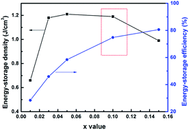
A new energy-storage ceramic system based on (1 − x)(Bi0.5Na0.5TiO3–BaTiO3)–xNaTaO3 ((1 − x)(BNT–BT)–xNT) is reported in this study. XRD refinement indicated a composition induced rhombohedral to tetragonal phase transition. All the samples exhibited a dense microstructure with an average grain size of 1.2–1.9 μm. The introduction of NT greatly improved the temperature stability of the dielectric properties for the BNT–BT system. For compositions x = 0.03–0.15, the working temperature range spanned over 260 °C satisfying TCC150 °C ≤ ±15%. The electric conductivity as a function of frequency followed the double power law. In the temperature region of 325–500 °C, the activation energy of DC conduction ranged from 1.47 eV to 1.71 eV, indicating intrinsic band-type electronic conduction. The optimum energy-storage properties were obtained in 0.90(BNT–BT)–0.10NT with an energy-storage density of 1.2 J cm−3 and energy-storage efficiency of 74.8% at 10 kV mm−1. The results demonstrate that (1 − x)(BNT–BT)–xNT ceramics are promising candidates for high-temperature energy-storage applications.


1. Introduction

Capacitors play an important role in energy-storage systems. Compared to batteries, capacitors possess faster charge–discharge times and higher power density.1,2 However, the energy that capacitor dielectrics can store is much less than fuel cells or lithium ion batteries.3 Thus, the development of new capacitor materials with a high energy-storage capacity is a challenge for researchers. Additionally, since electronic equipment is often exposed to extreme temperatures in industrial applications, such as space exploration and deep oil/gas well drilling,4,5 the temperature reliability of capacitor materials is also very important.

Bi0.5Na0.5TiO3 (BNT) based ceramics have been actively studied for energy-storage application in recent years.6–10 Among the reported systems, (1 − x)Bi0.5Na0.5TiO3xBaTiO3 (BNT–BT) binary solid solution at the morphotropic phase boundary (MPB, 0.06 ≤ x ≤ 0.10)11 is a promising candidate for high-temperature energy-storage capacitors. On the one hand, the existence of double dielectric anomalies over the studied temperature range can help to improve the temperature stability of the dielectric properties. On the other hand, BNT–BT shows large maximum polarization, which is favorable for obtaining high energy-storage density. Modifications of BNT-based high-temperature energy-storage ceramics focus on expanding the temperature range with stable permittivity, as well as improving their energy-storage density and efficiency.

Niobates are the most widely reported members to modify the dielectric and ferroelectric properties of BNT-based ceramics, such as NaNbO3,12,13 KNbO3,14,15 (Li, Ag)NbO3,16 Na0.5K0.5NbO3,17–20 and (Na, Bi)NbO3.21 Tantalum and niobium belong to same family in the periodic table of elements. According to J. König22 and M. Spreitzer,23 tantalate addition can significantly broaden the dielectric anomaly of BNT ceramics. However, the exact dielectric temperature stability has not been reported, neither has the effect of tantalate on the ferroelectric properties.

To explore the potential use of tantalate modified BNT-based ceramics for temperature-stable energy-storage application, a new system based on (1 − x)(0.92Bi0.5Na0.5TiO3–0.08BaTiO3)–xNaTaO3 ((1 − x)(BNT–BT)–xNT) ternary solid solution was prepared in this work. The effects of NT on the structure, dielectric stability, electrical properties, and energy-storage properties of the system were comprehensively investigated.

2. Experimental procedure

(1 − x)(BNT–BT)–xNT (x = 0.01, 0.03, 0.05, 0.10, 0.15) ceramic samples were prepared by traditional solid-state reaction method.8,24–26 First, the raw powders Bi2O3 (purity 99.0%), Na2CO3 (purity 99.8%), TiO2 (purity 98.5%), BaCO3 (purity 99.0%) and Ta2O5 (purity 99.99%) were mixed according to the stoichiometric formula and ball milled with zirconium media in ethanol for 24 h. After drying at 100 °C, the powder mixture was calcined at 800 °C for 2 h and subsequently ball-milled again for 24 h. Then, the powders were pressed into pellets of 12 mm in diameter and 1 mm in thickness under a uniaxial pressure of 200 MPa. The pellets were sintered at 1150 °C for 2 h. To minimize the evaporation of volatile elements, the pellets were embedded in self-source powder during sintering.

Phase structure was determined using X-ray powder diffraction (Cu Kα radiation, PANalytical X'Pert PRO, Eindhoven, the Netherlands) operated at 40 kV and 40 mA. Microstructure was studied by scanning electron microscope (Quanta 450 FEG, FEI, Hillsboro, USA). Electrodes were fabricated with fire-on silver paste at 500 °C for 15 min. Electrical properties measurements were carried out with a precision LCR meter (E4980A, Agilent, Santa Clara, USA) using a customer designed furnace and computer-controlled data collection system. To determine the ferroelectric properties, the sintered samples were polished to a thickness of 0.3 (±0.02) mm and then the test was performed using a ferroelectric material test system (HVI0403-239, Radiant Technology, USA) in a silicone oil bath at 10 Hz.

3. Results and discussion

3.1 Structure characterization

The room temperature XRD patterns of (1 − x)(BNT–BT)–xNT ceramics with 2θ = 20–80° (Fig. 1) show pure perovskite structure for all the samples. The Rietveld refinement was conducted to clarify the phase constitution. In agreement with recent work from G. Viola,27 optimal fits to the XRD patterns were achieved using a combination of the space groups R3c and P4bm. The lattice parameters, atomic positions of the Bi, Na, Ba, Ti, Ta, O atoms, and occupancy have been refined using X'Pert HighScore Plus software. The reliability factor Rwp (the subscript “wp” means “weighted profile”) value in each composition was below 10%, indicating a high credibility of the refinement. The lattice parameters obtained from the Rietveld refinement were listed in Table 1. It is obvious from the refinement results that rhombohedral R3c phase and tetragonal P4bm phase almost equally accounted for fifty percent in the sample x = 0.01. With the increase of NT content, P4bm gradually transformed into a dominating phase. When x = 0.15, P4bm phase fraction reached 79.4%. It is known that rhombohedral R3c is polar phase, tetragonal P4bm is weakly polar phase.28,29 The introduction of NT into BNT–BT system caused polar → weakly polar phase transition. The composition change induced phase constitution transition is also reported in alkalis-substituted BNT-based system27 and in rare earth modified BiFeO3 multiferroics.30
image file: c6ra11744a-f1.tif
Fig. 1 Rietveld refinement patterns of (1 − x)(BNT–BT)–xNT ceramics. The black circles and the red lines represent the observed and refinement data, respectively. The blue lines are the difference between the observed and calculated diffraction patterns, the pink and green bars are Bragg reflections for R3c and P4bm.
Table 1 Calculated lattice parameters of (1 − x)(BNT–BT)–xNT ceramic samples by refinement of room-temperature XRD data
Composition Phase fraction (%) Lattice parameters Rwp
a (Å) c (Å)
x = 0.01 R3c 49.5 5.561 13.619 6.2%
P4bm 50.5 5.522 3.901
x = 0.03 R3c 41.1 5.548 13.623 6.4%
P4bm 58.9 5.519 3.900
x = 0.05 R3c 30.5 5.546 13.626 9.1%
P4bm 69.5 5.519 3.907
x = 0.10 R3c 24.8 5.536 13.642 4.7%
P4bm 75.2 5.524 3.901
x = 0.15 R3c 20.6 5.534 13.624 4.6%
P4bm 79.4 5.521 3.908


Fig. 2 illustrates the SEM images of (1 − x)(BNT–BT)–xNT ceramics thermal etched at 1000 °C for 30 min. All the samples exhibited dense microstructure with no pores. Promoted grain growth can be observed with the addition of NT. The average grain sizes were determined by the linear intercept method to be 1.2, 1.3, 1.3, 1.4, 1.9 μm for x = 0.01, 0.03, 0.05, 0.10, 0.15 respectively. Similar trends have been reported in oxide added and niobate modified BNT–BT ceramics.12,31 As is generally recognized, A-site elements such as bismuth and sodium in BNT-based systems volatilize inevitably due to their low melting points,12,32 leading to the presence of oxygen vacancies, which is beneficial to mass transportation during sintering.31 This is assumed to be responsible for the grain growth in (1 − x)(BNT–BT)–xNT system with the increase of NT content.


image file: c6ra11744a-f2.tif
Fig. 2 SEM images of (1 − x)(BNT–BT)–xNT ceramic samples: (a) x = 0.01, (b) x = 0.03, (c) x = 0.05, (d) x = 0.10, (e) x = 0.15.

3.2 Dielectric properties

The permittivity and dielectric loss as a function of temperature at different frequencies (1 kHz, 10 kHz, 100 kHz) for (1 − x)(BNT–BT)–xNT (x = 0.01–0.15) ceramics were presented in Fig. 3(a)–(e). The dielectric properties of pure BNT–BT without NT addition were reported in ref .12.
image file: c6ra11744a-f3.tif
Fig. 3 (a–e) Dielectric constant and dielectric loss as a function of temperature measured at different frequencies, (f) permittivity gap |εsεm|, Ts, and Tm at 1 kHz of (1 − x)(BNT–BT)–xNT ceramics.

The temperature dependence of permittivity curves were characterized by double dielectric anomalies. As shown in Fig. 3(a), the first dielectric anomaly was located at the temperature of Ts (about 105 °C at 1 kHz), accompanied with obvious frequency dispersion, which is caused by thermal evolution of R3c and P4bm polar nano-regions mixture.28 The second dielectric anomaly was located at the temperature of Tm (around 250 °C at 1 kHz), which is also regarded as the Curie temperature (TC).33,34 It is the temperature at which the permittivity (εm) reaches a maximum value. Tm was identified as the antiferroelectric–paraelectric phase transition point.19,35 However, it has been demonstrated by in situ Transmission Electron Microscopy recently that no structural change can be observed across Tm.29 Instead, the anomaly at Tm is believed to originate from a mixed contribution of R3cP4bm transition and thermal evolution of P4bm polar nano-regions.28 Compared to pure BNT (TC = 320 °C),36 the Curie point of this system was largely reduced by the introduction of BT and NT.

In the temperature-dependent loss tangent curves, a peak in 0–90 °C temperature range can be observed for all compositions, which is often defined as the depolarization temperature (Td) of the system.25 In the range of 150–350 °C, the loss tangent was lower than 0.04. At higher temperature (≥400 °C), the dielectric loss underwent a sharp rise. This is related to the increased conductivity, which will be discussed in the following part.

With the increase of NT addition, Ts continuously decreased while Tm remained unchanged, as shown in Fig. 3(f). The permittivity gap |εsεm| largely reduced from ∼1660 in x = 0.01 to ∼185 in x = 0.10 (Fig. 3(f)), leading to an improvement in the temperature stability of permittivity. We adopted temperature coefficient of capacitance (TCC) to evaluate the temperature stability of dielectric properties for (1 − x)(BNT–BT)–xNT ceramics in this paper, as shown in eqn (1).

 
image file: c6ra11744a-t1.tif(1)
where CT represents the capacitance at any temperature within the measuring range, Cbase temp. is the capacitance at base temperature.

In the study of temperature stable dielectrics, such as XnR (X represents the minimum temperature of −55 °C; n means the maximum temperature, n = 7 for 125 °C and n = 8 for 150 °C; R symbolizes percentage of the capacitance variation limit ±15% in the whole temperature range) multi-layer ceramic capacitor (MLCC) dielectrics and high-temperature capacitor materials, researchers employ different benchmark working temperatures to calculate TCC.37,38 Among them, 25 °C and 150 °C are the most commonly used ones. Therefore, we evaluated the temperature stability of dielectric properties for (1 − x)(BNT–BT)–xNT ceramics in the benchmark of both 25 °C and 150 °C.

Fig. 4 shows the variation of TCC in the range of −55 °C to 400 °C at 1 kHz, the dashed lines indicate the working temperature ranges with TCC ≤ ±15%. It should be noted that the working temperature range of x = 0.01–0.10 was too narrow on the baseline of 25 °C, so the data was omitted in Fig. 4(a). For the composition x = 0.15, the operational temperature range expanded to −6 to 312 °C with moderate permittivity (εr, 25 °C = 1472) and low dielectric loss (tan[thin space (1/6-em)]δ, 25 °C = 0.031), demonstrating a potential in wide-temperature stable capacitor material. Whereas the dielectric stability at the low temperature end (lower than 0 °C) need to be further improved. On the baseline of 150 °C (Fig. 4(b)), compositions with x = 0.03–0.15 all displayed favorable dielectric temperature stability. The working temperature range spanned over 260 °C (Table 2), which is superior to previously reported high-temperature dielectrics.37


image file: c6ra11744a-f4.tif
Fig. 4 TCC of (1 − x)(BNT–BT)–xNT ceramics at 1 kHz: (a) base temperature 25 °C; (b) base temperature 150 °C.
Table 2 Dielectric properties of (1 − x)(BNT–BT)–xNT ceramics at 1 kHz
x εr (25 °C) tan[thin space (1/6-em)]δ (25 °C) Temperature range satisfying |ΔC/C25 °C| ≤ 15% εr (150 °C) tan[thin space (1/6-em)]δ (150 °C) Temperature range satisfying |ΔC/C150 °C| ≤ 15%
0.01 1981 0.062 4758 0.007 94–200 °C
0.03 1767 0.067 3533 0.005 77–356 °C
0.05 1785 0.062 3130 0.004 66–336 °C
0.10 1722 0.048 2226 0.004 36–295 °C
0.15 1472 0.031 −6 to 312 °C 1554 0.004 3–284 °C


3.3 AC conductivity

Fig. 5 shows the frequency dependence of AC conductivity for (1 − x)(BNT–BT)–xNT ceramics at several temperature points between 200 °C and 500 °C. In the lower temperature range (200–375 °C), AC conductivity underwent an exponential growth with frequency in the whole range from 10 Hz to 1 MHz. At higher temperature (400–500 °C), AC conductivity behaved differently. At low frequency, conductivity almost kept constant, while in high frequency region, conductivity increased with frequency. The boundary frequency of these two regions is known as hopping frequency.39,40 With temperature increasing, the hopping frequency shifted towards higher value in all the compositions.
image file: c6ra11744a-f5.tif
Fig. 5 Frequency dependence of AC conductivity for (1 − x)(BNT–BT)–xNT ceramics at several temperature points between 200 °C and 500 °C.

AC conductivity in solid materials can be expressed as:41

 
σac = σ(0) + σ(ω) (2)
where ω is angular frequency; σ(0) is frequency independent DC conductivity part, sometimes it is written as σdc;42 σ(ω) is frequency dependent part. σ(ω) obeys universal dynamic response:43–45 σ(ω) = s, which is also called Jonscher's power law,40,46 0 < s < 1.

However, the AC conductivity data in Fig. 5 did not obey the simple Jonscher's power law, but double power law:47–49

 
σac = σ(0) + A1ωs1 + A2ωs2 (3)
which describes three different contributions to conductivity. (i) σ(0) corresponds to the long range transport of mobile charge carriers, i.e., DC conductivity;50 (ii) A1ωs1 (0 < s1 < 1) characterizes the translational hopping motion (or short range hopping) at low frequency;51 (iii) A2ωs2 (0 < s2 < 2) is associated with localized or reorientational hopping motion.51,52 In ceramic systems with distinct electrical micro-structures, A1ωs1 and A2ωs2 are supposed to be related to grain boundary and grain, respectively.53

Fig. 6 shows the variation of power exponents s1 and s2 with temperature fitted by the double power law. s1 represented the power exponent in 20 Hz to 10 kHz, ranging in 0.4–1.0. s2 characterized the power exponent above 10 kHz, ranging from 0.6 to 1.7. It should be noted that the AC conductivity above 400 °C kept constant in a wide frequency range for all the compositions, so the data above 400 °C was fitted by simple power law instead. Thus only s2 can be observed in Fig. 6 in 400–500 °C. With the increase of temperature, both s1 and s2 gradually reduced. It is known that the power exponents represent the degree of interaction between the mobile ions and the lattice, dependent on intrinsic material characteristics and temperature.54,55 The increased interaction at high temperature was supposed to be responsible for the decrease of s1 and s2.54 Additionally, the exponent s2 in all the samples reached a minimum at ∼400 °C, which was the onset of the sharp rise in temperature-dependent dielectric loss curves (Fig. 3).


image file: c6ra11744a-f6.tif
Fig. 6 (a–e) Temperature dependence of the exponents s1 and s2, (f) comparison of the exponents at 325 °C for (1 − x)(BNT–BT)–xNT ceramics.

Fig. 7(a)–(e) represents the variation of conductivity with inverse of absolute temperature (i.e. ln[thin space (1/6-em)]σac versus 1000/T) at different indicated frequencies for (1 − x)(BNT–BT)–xNT ceramics, in which the DC conductivity values were obtained by the above power law fitting. The conductivities gradually increased with increasing temperature, indicating a thermally activated conduction process.56–58 The activation energy of conduction can be calculated by Arrhenius relationship:41,59–61

 
image file: c6ra11744a-t2.tif(4)
where σ0 is the pre-exponential factor, Ea is the activation energy of conduction, kB is the Boltzmann constant, kB = 1.38 × 10⁻²³ J K−1. The obtained Ea values were listed in Fig. 7(f) and (g). Within the measuring temperature range, the activation energy of conduction (i.e. the slope in Fig. 7(a)–(e)) exhibited different values in the low temperature region (150–300 °C) and the high temperature region (325–500 °C). Within the same temperature region, Ea reduced with frequency, which is also observed in other systems.48,62 As mentioned above, at low frequency, the conductivity is related to the long range transport of mobile charge carriers, corresponding to large Ea. At high frequency, the reorientational hopping motion of the charge carriers is restricted to the neighbouring lattice sites,49 thus corresponding to small Ea value. At a certain frequency for each composition, Ea in the high temperature region was much larger than that in the low temperature region. In 325–500 °C, the activation energy of DC conduction ranged in 1.47–1.71 eV, which is close to the reported data in BNT-based ceramics.36,56,63 Since the band gap of BNT–BT ceramics is around 3.2–3.4 eV,64–66 there could be electronic states near the Fermi-level.61 So, it is supposed that (1 − x)(BNT–BT)–xNT system exhibits intrinsic band-type electronic conduction, which is analogous to that in BNT–BT–CZ,63 BNT–BT–KNN56 and BNT–BT–NBN21 materials.


image file: c6ra11744a-f7.tif
Fig. 7 (a–e) Temperature-dependent variation of conductivity at different indicated frequencies and (f and g) the activation energy of conduction at different temperature range for (1 − x)(BNT–BT)–xNT ceramics.

3.4 Energy-storage properties

Energy-storage parameters were calculated based on the PE loop of the samples. As shown in Fig. 8, the discharge (or recoverable) energy-storage density W was evaluated by integrating the area between the polarization axis and the discharge curve. The area of the PE loop represented the energy loss density WLoss. Due to the existence of WLoss, the energy that can be recovered is smaller than the energy delivered to the capacitor.3 Thus, the energy-storage efficiency η is also an important parameter for energy-storage capacitor dielectrics.
image file: c6ra11744a-f8.tif
Fig. 8 Schematic diagram of energy-storage parameters calculation.

Recoverable energy-storage density:67

 
image file: c6ra11744a-t3.tif(5)

Charge energy-storage density:

 
W′ = W + WLoss (6)

Energy-storage efficiency:

 
image file: c6ra11744a-t4.tif(7)

The PE hysteresis loops of (1 − x)(BNT–BT)–xNT ceramics measured at 10 Hz and room temperature under different electric field were shown in Fig. 9. In all the compositions, the polarization did not saturate within the measured field range. For x = 0.01, the maximum polarization (Pm) increased from 9.3 to 44.8 μC cm−2 with electric field increasing from 2 to 8 kV mm−1. Under 10 kV mm−1, the PE loop of x = 0.01 exhibited typical relaxor ferroelectric characteristics with large Pm (∼50.9 μC cm−2) and medium remnant polarization (Pr ∼ 24.9 μC cm−2). With increase in NT content, the PE loop became more and more slim. When x = 0.15, Pm and Pr reduced to 25.1 μC cm−2 and 2.1 μC cm−2 at 10 kV mm−1, respectively. The variation of polarization as a function of composition was shown in Fig. 10(a). The change of PE loops indicated that the long-range ferroelectric order was disturbed with the introduction of NT. This is caused by the decrease of polar rhombohedral phase proportion and increase of weakly polar tetragonal phase proportion, as certified by XRD analysis.


image file: c6ra11744a-f9.tif
Fig. 9 PE loops and energy-storage densities of (1 − x)(BNT–BT)–xNT ceramics under different electric field.

image file: c6ra11744a-f10.tif
Fig. 10 (a) Pm, Pr, PmPr (b) energy-storage density and energy-storage efficiency of (1 − x)(BNT–BT)–xNT ceramics under 10 kV mm−1.

The insets of Fig. 9 shows the energy-storage densities as a function of electric field. The WE curves underwent a gradual increment in the slope under lower electric field and then maintained linearity to the maximum applied electric field. Fig. 10(b) summarizes the calculated energy-storage density and energy-storage efficiency of all the samples at 10 kV mm−1. For x = 0.01, the energy-storage density was no higher than 0.7 J cm−3 due to the large remnant polarization. With the increase of NT content, W exhibited a great increase, reaching 1.1–1.2 J cm−3 for x = 0.03–0.10. However, further addition of NT reduced the energy-storage density since the maximum polarization sharply dropped. For the energy-storage efficiency, it kept increasing from 28.4% in x = 0.01–80.6% in x = 0.15. By an overall consideration of W and η, the optimum energy-storage properties at 10 kV mm−1 was obtained in 0.90(BNT–BT)–0.10NT with W = 1.2 J cm−3 and η = 74.8%, which is comparable to other reported BNT-based energy-storage ceramics.6,20,68

4. Conclusion

Dense (1 − x)(BNT–BT)–xNT (0.01 ≤ x ≤ 0.15) ceramics were fabricated via high-temperature solid-state reaction method. All the samples exhibited single perovskite structure with no secondary impurity. XRD refinement indicated a composition induced polar rhombohedral phase (space group R3c) → weakly polar tetragonal phase (space group P4bm) transition. With the increase of NT addition, the permittivity gap at the anomaly temperatures |εsεm| largely reduced, leading to favorable dielectric temperature stability. In the compositions of x = 0.03–0.15, the working temperature range spanned over 260 °C satisfying TCC150 °C ≤ ±15%. In the high temperature region (325–500 °C), the activation energy of DC conduction Ea = 1.47–1.71 eV, which was approximately half the band gap of BNT–BT ceramics, indicating intrinsic band-type electronic conduction. The optimum energy-storage properties was obtained in x = 0.10 with W = 1.2 J cm−3 and η = 74.8% at 10 kV mm−1.

Acknowledgements

This work was supported by National Natural Science Foundation of China (No. 51372191), National Key Basic Research Program of China (973 Program) (No. 2015CB654601), International Science and Technology Cooperation Program of China (2011DFA52680), the Fundamental Research Funds for the Central Universities (WUT: 152401002 and 152410002).

References

  1. S. Kwon, W. Hackenberger, E. Alberta, E. Furman and M. Lanagan, IEEE Electr. Insul. Mag., 2011, 27(2), 43–55 CrossRef.
  2. K. Yao, S. Chen, M. Rahimabady, M. S. Mirshekarloo, S. Yu and F. E. H. Tay, et al., IEEE Trans. Ultrason. Ferroelectrics Freq. Contr., 2011, 58(9), 1968–1974 CrossRef PubMed.
  3. T. M. Correia, M. McMillen, M. K. Rokosz, P. M. Weaver, J. M. Gregg and G. Viola, et al., J. Am. Ceram. Soc., 2013, 96(9), 2699–2702 CrossRef CAS.
  4. P. Hagler, P. Henson and R. W. Johnson, IEEE Trans. Ind. Electron., 2011, 58(7), 2673–2682 CrossRef.
  5. R. Dittmer, E.-M. Anton, W. Jo, H. Simons, J. E. Daniels and M. Hoffman, et al., J. Am. Ceram. Soc., 2012, 95(11), 3519–3524 CrossRef CAS.
  6. J. Ye, Y. Liu, Y. Lu, J. Ding, C. Ma and H. Qian, et al., J. Mater. Sci.: Mater. Electron., 2014, 25(10), 4632–4637 CrossRef CAS.
  7. G. Viola, H. Ning, M. J. Reece, R. Wilson, T. Correia and P. Weaver, et al., J. Phys. D: Appl. Phys., 2012, 45(35), 355302 CrossRef.
  8. R. A. Malik, A. Hussain, A. Zaman, A. Maqbool, J. U. Rahman and T. K. Song, et al., RSC Adv., 2015, 5(117), 96953–96964 RSC.
  9. X. Lu, J. Xu, L. Yang, C. Zhou, Y. Zhao and C. Yuan, et al., Journal of Materiomics, 2016, 2(1), 87–93 CrossRef.
  10. Y. Pu, M. Yao, H. Liu and T. Frömling, J. Eur. Ceram. Soc., 2016, 36(10), 2461–2468 CrossRef CAS.
  11. M. Chen, Q. Xu, B. H. Kim, B. K. Ahn, J. H. Ko and W. J. Kang, et al., J. Eur. Ceram. Soc., 2008, 28(4), 843–849 CrossRef CAS.
  12. Q. Xu, T. Li, H. Hao, S. Zhang, Z. Wang and M. Cao, et al., J. Eur. Ceram. Soc., 2015, 35(2), 545–553 CrossRef CAS.
  13. Q. Xu, Z. Song, W. Tang, H. Hao, L. Zhang and M. Appiah, et al., J. Am. Ceram. Soc., 2015, 98(10), 3119–3126 CrossRef CAS.
  14. X. Jiang, B. Wang, L. Luo, W. Li, J. Zhou and H. Chen, J. Solid State Chem., 2014, 213, 72–78 CrossRef CAS.
  15. H. Ni, L. Luo, W. Li, Y. Zhu and H. Luo, J. Alloys Compd., 2011, 509(9), 3958–3962 CrossRef CAS.
  16. L. Wu, N. Liu, F. Zhou, W. Wu, Y. Teng and Y. Li, J. Alloys Compd., 2010, 507(2), 479–483 CrossRef CAS.
  17. J. Ding, Y. Liu, Y. Lu, H. Qian, H. Gao and H. Chen, et al., Mater. Lett., 2014, 114, 107–110 CrossRef CAS.
  18. F. Gao, X. Dong, C. Mao, F. Cao, G. Wang and S. T. Zhang, J. Am. Ceram. Soc., 2011, 94(12), 4162–4164 CrossRef CAS.
  19. F. Gao, X. Dong, C. Mao, W. Liu, H. Zhang and L. Yang, et al., J. Am. Ceram. Soc., 2011, 94(12), 4382–4386 CrossRef CAS.
  20. J. Hao, Z. Xu, R. Chu, W. Li, D. Juan and F. Peng, Solid State Commun., 2015, 204, 19–22 CrossRef CAS.
  21. Q. Xu, M. T. Lanagan, X. Huang, J. Xie, L. Zhang and H. Hao, et al., Ceram. Int., 2016, 42(8), 9728–9736 CrossRef CAS.
  22. J. König, B. Jančar and D. Suvorov, J. Am. Ceram. Soc., 2007, 90(11), 3621–3627 CrossRef.
  23. M. Spreitzer, J. König, B. Jančar and D. Suvorov, EEE Trans. Ultrason. Ferroelectrics Freq. Contr., 2007, 54(12), 2617–2622 CrossRef PubMed.
  24. J. E. Daniels, W. Jo, J. Rödel, V. Honkimäki and J. L. Jones, Acta Mater., 2010, 58(6), 2103–2111 CrossRef CAS.
  25. E.-M. Anton, W. Jo, D. Damjanovic and J. R. Rödel, J. Appl. Phys., 2011, 110(9), 094108 CrossRef.
  26. S.-T. Zhang, A. B. Kounga, E. Aulbach, T. Granzow, W. Jo and H.-J. Kleebe, et al., J. Appl. Phys., 2008, 103(3), 034107 CrossRef.
  27. G. Viola, R. Mkinnon, V. Koval, A. Adomkevicius, S. Dunn and H. Yan, J. Phys. Chem. C, 2014, 118(16), 8564–8570 CrossRef CAS.
  28. W. Jo, S. Schaab, E. Sapper, L. A. Schmitt, H.-J. Kleebe and A. J. Bell, et al., J. Appl. Phys., 2011, 110(7), 074106 CrossRef.
  29. C. Ma, X. Tan and H. J. Kleebe, J. Am. Ceram. Soc., 2011, 94(11), 4040–4044 CrossRef CAS.
  30. V. A. Khomchenko, V. V. Shvartsman, P. Borisov, W. Kleemann, D. A. Kiselev and I. K. Bdikin, et al., Acta Mater., 2009, 57(17), 5137–5145 CrossRef CAS.
  31. Q. Xu, M. Chen, W. Chen, H.-X. Liu, B.-H. Kim and B.-K. Ahn, Acta Mater., 2008, 56(3), 642–650 CrossRef CAS.
  32. M. Zhu, H. Hu, N. Lei, Y. Hou and H. Yan, Appl. Phys. Lett., 2009, 94(18), 182901 CrossRef.
  33. K. Kumar and B. Kumar, Ceram. Int., 2012, 38(2), 1157–1165 CrossRef CAS.
  34. H. Y. Ma, X. M. Chen, J. Wang, K. T. Huo, H. L. Lian and P. Liu, Ceram. Int., 2013, 39(4), 3721–3729 CrossRef CAS.
  35. S.-T. Zhang, A. B. Kounga, E. Aulbach, W. Jo, T. Granzow and H. Ehrenberg, et al., J. Appl. Phys., 2008, 103(3), 034108 CrossRef.
  36. J. East and D. C. Sinclair, J. Mater. Sci. Lett., 1997, 16(6), 422–425 CrossRef CAS.
  37. R. Dittmer, W. Jo, D. Damjanovic and J. R. Rödel, J. Appl. Phys., 2011, 109(3), 034107 CrossRef.
  38. H. Hao, M. Liu, H. Liu, S. Zhang, X. Shu and T. Wang, et al., RSC Adv., 2015, 5(12), 8868–8876 RSC.
  39. R. Rani, S. Sharma, R. Rai and A. L. Kholkin, Solid State Sci., 2013, 17, 46–53 CrossRef CAS.
  40. S. K. Rout, A. Hussian, J. S. Lee, I. W. Kim and S. I. Woo, J. Alloys Compd., 2009, 477(1–2), 706–711 CrossRef CAS.
  41. K. Prasad, K. Kumari Lily, K. P. Chandra, K. L. Yadav and S. Sen, Adv. Appl. Ceram., 2013, 106(5), 241–246 CrossRef.
  42. J. S. Kim, A. Hussain, M.-H. Kim and T. K. Song, J. Korean Phys. Soc., 2012, 61(6), 951–955 CrossRef CAS.
  43. J. R. Macdonald, J. Non-Cryst. Solids, 1997, 210(1), 70–86 CrossRef CAS.
  44. A. K. Jonscher, Nature, 1977, 267(5613), 673–679 CrossRef CAS.
  45. A. K. Jonscher, Nature, 1975, 256(5518), 566–568 CrossRef CAS.
  46. A. K. Roy, A. Singh, K. Kumari, K. Amar Nath, A. Prasad and K. Prasad, ISRN Ceram., 2012, 2012, 1–10 CrossRef.
  47. N. Ortega, A. Kumar, P. Bhattacharya, S. B. Majumder and R. S. Katiyar, Phys. Rev. B: Condens. Matter Mater. Phys., 2008, 77(1), 014111 CrossRef.
  48. A. Roy, K. Prasad and A. Prasad, Process. Appl. Ceram., 2013, 7(2), 81–91 CrossRef CAS.
  49. A. K. Roy, K. Prasad and A. Prasad, ISRN Ceram., 2013, 2013, 1–12 CrossRef.
  50. B. Parija and S. Panigrahi, Ferroelectr., Lett. Sect., 2012, 39(1–3), 38–55 CrossRef CAS.
  51. K. Funke, Prog. Solid State Chem., 1993, 22(2), 111–195 CrossRef CAS.
  52. A. A. A. Youssef, Z. Naturforsch., A: Phys. Sci., 2002, 57(5), 263–269 CrossRef CAS.
  53. S. Kumar and K. B. R. Varma, Curr. Appl. Phys., 2011, 11(2), 203–210 CrossRef.
  54. B. K. Barick, K. K. Mishra, A. K. Arora, R. N. P. Choudhary and D. K. Pradhan, J. Phys. D: Appl. Phys., 2011, 44(35), 355402 CrossRef.
  55. D. P. Almond, A. R. West and R. J. Grant, Solid State Commun., 1982, 44(8), 1277–1280 CrossRef CAS.
  56. J. Zang, M. Li, D. C. Sinclair, W. Jo, J. Rödel and S. Zhang, J. Am. Ceram. Soc., 2014, 97(5), 1523–1529 CrossRef CAS.
  57. Z. Song, S. Zhang, H. Liu, H. Hao, M. Cao and Q. Li, et al., J. Am. Ceram. Soc., 2015, 98(10), 3212–3222 CrossRef CAS.
  58. A. Hussain, J. S. Kim, J. U. Rahman, A. Maqbool, T. K. Song and W. J. Kim, et al., Ferroelectrics, 2014, 464(1), 107–115 CrossRef CAS.
  59. J. Portelles, N. S. Almodovar, J. Fuentes, O. Raymond, J. Heiras and J. M. Siqueiros, J. Appl. Phys., 2008, 104(7), 073511 CrossRef.
  60. M. A. Rafiq, M. E. Costa, A. Tkach and P. M. Vilarinho, Cryst. Growth Des., 2015, 15(3), 1289–1294 Search PubMed.
  61. Q. Xu, M. T. Lanagan, W. Luo, L. Zhang, J. Xie and H. Hao, et al., J. Eur. Ceram. Soc., 2016, 36(10), 2469–2477 CrossRef CAS.
  62. K. S. Rao, K. C. V. Rajulu, B. Tilak and A. Swathi, Nat. Sci., 2010, 2(4), 357–367 CAS.
  63. J. Zang, M. Li, D. C. Sinclair, T. Frömling, W. Jo and J. Rödel, et al., J. Am. Ceram. Soc., 2014, 97(9), 2825–2831 CrossRef CAS.
  64. M. Bousquet, J. R. Ducleère, E. Orhan, A. Boulle, C. Bachelet and C. Champeaux, J. Appl. Phys., 2010, 107(10), 104107 CrossRef.
  65. M. Cernea, A. C. Galca, M. C. Cioangher, C. Dragoi and G. Ioncea, J. Mater. Sci., 2011, 46(17), 5621–5627 CrossRef CAS.
  66. M. Cernea, L. Trupina, C. Dragoi, A.-C. Galca and L. Trinca, J. Mater. Sci., 2012, 47(19), 6966–6971 CrossRef CAS.
  67. N. H. Fletcher, A. D. Hilton and B. W. Ricketts, J. Phys. D: Appl. Phys., 1996, 29(1), 253–258 CrossRef CAS.
  68. M. Yao, Y. Pu, H. Zheng, L. Zhang, M. Chen and Y. Cui, Ceram. Int., 2016, 42(7), 8974–8979 CrossRef CAS.

This journal is © The Royal Society of Chemistry 2016