DOI:
10.1039/C6RA07632G
(Paper)
RSC Adv., 2016,
6, 70832-70841
Effective cementation and removal of arsenic with copper powder in a hydrochloric acid system
Received
23rd March 2016
, Accepted 20th July 2016
First published on 20th July 2016
Abstract
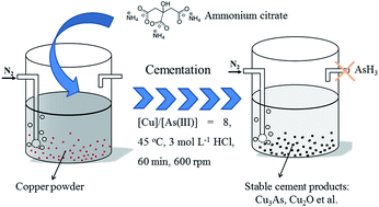
This work investigated the removal and cementation of arsenic from a hydrochloric acid system with copper powder. Thermodynamic analysis and cyclic voltammetry test were conducted to evaluate the feasibility of cementation. The effect of reaction temperature, mole ratio of Cu to As(III), stirring rate, reaction time and HCl concentration on the cementation efficiency of arsenic were investigated systematically. 94.75% of the arsenic could be removed under optimized conditions: mole ratio of Cu/As = 8 at 45 °C for 60 min. The structure and morphologies of the cement products were characterized by X-ray diffraction and scanning electron microscopy, respectively. The results show that the reaction temperature has little influence on the morphology of the cement products which consist of particles with various sizes, but has a great influence on the cementation efficiency. During the cementation process, the rate-controlling mechanisms are changed at different temperatures. It is diffusion controlled at the high temperature region (45–50 °C) with an activation energy of 26.7 kJ mol−1, while it is surface reaction controlled at the lower temperature region (30–45 °C) with an activation energy of 145.7 kJ mol−1. Ammonium citrate can efficiently inhibit the evolution of arsane, while has little influence on the cementation efficiency of arsenic.
1. Introduction
Arsenic is one of the most toxic and carcinogenic chemical elements and is regarded as the first priority issue among toxic substances by the World Health Organization.1–6 Arsenic contamination of water and groundwater has become a major concern on a global scale, especially in developing countries. Based on human health data, a concentration of 10 ppm has been recommended by WHO as a guideline value for drinking water.7,8
Till now, various technologies and approaches have been exploited to remove arsenic, such as ion exchange,9 precipitation,10–13 reverse osmosis,14–16 bioremediation,17 and adsorption,18–23 electrodeposition,24–26 coagulation,27–30 etc. However, they are usually subject to low efficiency, strict operation condition, high cost or expensive materials. Besides, abundant arsenic waste residue may be generated, easy causing secondary pollution.
Cementation is favored by hydrometallurgy researchers and has been extensively used in industry due to the relative simple operation, ease of control, high efficient recovery rate to valuable metals.31–34 Zinc and iron are the most common cementation agent in industry applications owing to their strong reductive ability. Generally, hydrogen will generate in the acid solution system if zinc and iron were used as the cementation agent. This would lead to the produce of arsane if arsenic ions were contained. In addition, copper, which is less active than zinc and iron, is also used as cementation agent for the recovery of antimony35 or noble metals, such rhodium,31 silver,36 gold37 and so on. During the cementation process, copper is first oxidized to cuprous ions, which can further form copper complexes with chloride in HCl solution system,38 leading to the redox potential significantly reduced compared to the standard potential of pure metal ion system.39 This makes it possible to cement other metals with relative negative potential.
In this paper, the arsenic in hydrochloric acid system was cemented and removed by copper powder. Cyclic voltammetry test and thermodynamic analysis are conducted to investigate the cementation process. Batch experiments were carried out to optimize the cementation condition. The structure and morphology of the cement products were characterized by XRD and SEM, and the cementation mechanism was proposed. Furthermore, ammonium citrate tribasic was introduced to prevent the evolution of arsane.
2. Experimental section
2.1 Regents and solutions
Arsenic trichloride (AsCl3) was distilled in laboratory, other reagents are analytical pure and used as received without further purification. All aqueous solutions were freshly prepared with deionized water. The As(III) stock solution (0.15 mol L−1) was prepared by dissolving desired distilled AsCl3 into 3.0 mol L−1 HCl. The working solution containing 0.05 mol L−1 As(III) was prepared by diluting the stock solutions with 3.0 mol L−1 HCl immediately prior to their use.
2.2 Electrochemical analysis
Cyclic voltammetry (CV) measurements were carried out on a CHI630b electrochemical workstation (CH Instrument, Shanghai, China) in a classical three-electrode compartment. A glass carbon (GC) electrode (∼0.6 cm diameter), a saturated calomel electrode (SCE) and a platinum plate with an exposed area of 2.0 cm2 were used as the working, reference and counter electrodes, respectively. The tests were performed at 25 °C with a scan rate of 0.1 V s−1. CV characterization in pure copper and arsenic system contains 0.15 mol L−1 Cu(II) and 0.05 mol L−1 As(III), respectively. While for the copper and arsenic mixture system, 0.15 mol L−1 Cu(II) and 0.05 mol L−1 As(III) are contained.
2.3 Batch cementation experiments
The cementation of As(III) on copper powder was conducted in batch experiments under magnetic stirring and bubbled nitrogen through the solution all the time. All cementation tests were conducted in a cylindrical glass reactor with diameter of 7.5 cm. When the system reached certain temperature (30, 35, 40, 45 and 50 °C), desired dosages of Cu powder (200 mesh) was added into 200 mL of 0.05 mol L−1 As(III) solution. After reaction for 10, 15, 30, 45 and 60 min, appropriate volume solution was withdrawn and analyzed for determining the concentration of residual arsenic and generated copper ions. For the detection of As3+ and Cu+ ions with high concentrations, iodometric was conducted. While the detection of ions with low concentration was performed by inductively coupled plasma-mass spectrometry (ICP-MS, USA, Thermo X Series II).
2.4 Analysis and characterization
Arsenic content measured by iodometric was carried out with the guidance of YS-T461.4-2003 (Chinese industrial standard)40 and performed as followed. 30–45 mL of HCl (37%) was added into a separating funnel with the experimental arsenic solution. TiCl3 (15.0–20.0%, in 30% HCl) was dropped into the separating funnel and gently shaking it to get a light purple solution. Then 1.5 mL TiCl3 was extra added. 25 mL benzene was added into the mixture solution and extracting for 2 min. Transfer the water phase to another separating funnel for the secondary extraction and 20 mL benzene was added. Shake the funnel vigorously and keeping the stopper firmly closed. Collect the upper organic phase and added into the first separating funnel. 10 mL of HCl (37%) was added for extracting the organic phase. Then 25 mL deionized water was added and shaken for back-extraction. Transfer the aqueous phase into a conical flask. NaHCO3 was added into the conical flask until no gas generates and 3 g NaHCO3 was extra added. At this time 10 mL of 0.05 mol L−1 iodine was added. Then freshly prepared Na2S2O3 (0.1 mol L−1) solution was titrated until most of the iodine has reacted (the color of the solution became light yellow). 5 mL of 0.5% starch solution was added and the color of the solution turned to be blue. The titration of Na2S2O3 was continued until blue color disappeared. The amount of arsenic was calculated from the volume of Na2S2O3 used. All titrations were repeated three times.
Copper content measured by iodometric was carried out with the guidance of GB/T 15249.3-2009 (Chinese national standard)41 and performed as followed. 5 mL of HCl (37%) and 5 mL of H2O2 (30%) were added in sequence into 1 mL of experimental copper solution. The mixture solution was heated until ∼2 mL solution remained and cooled down. Then dilute the solution with 30 mL deionized water. Ammonia (1
:
1) was added until white precipitation appeared. Concentrated phosphoric acid was added until all precipitation was dissolved. Then 5 mL phosphoric acid was extra added. Cooling down the solution to room temperature and dilute by 40 mL deionized water. 5 mL of 20% KI solution was added. Then freshly prepared Na2S2O3 (0.1 mol L−1) solution was titrated until most of the iodine has reacted (the color of the solution became light yellow). At this time 10 mL of 20% KSCN was added and keep on titrate with Na2S2O3 solution until the yellow disappeared. Then 5 mL of 0.5% starch solution was added and the color of the solution turned to be blue. The addition of Na2S2O3 was continued until blue color disappeared. The amount of copper was calculated from the volume of Na2S2O3 used. All titrations were repeated three times.
Ignore the change in the solution volume before and after cementation and the component taken away by nitrogen, the cementation efficiency (%) of arsenic on copper was calculated using the following equation:
|
η/% = [(c0 − ct)/c0] × 100%
| (1) |
where
c0 is the initial arsenic concentration (0.05 mol L
−1), and
ct is the arsenic concentration at moment of
t.
N2 was keeping bubbled to flushing out the possible generated arsane remaining in the vessel. A scrubber containing 4 mol L−1 HNO3 solution was used to oxidize the possible generated arsane during cementation. And the contents of arsenic in the tail solutions were analyzed by ICP-MS.
X-ray diffraction (XRD) patterns of the cement product were recorded on a RIGAKU D/Max 2550 PC diffractometer equipped with Cu Kα radiation (λ = 1.54059 Å) at 40 kV and 40 mA. The morphology and composition of the cement product were characterized by scanning electron microscopy (SEM, VEGA3, operated at 15 kV) equipped with energy dispersive X-ray (EDX) microanalysis (Oxford EDS Inca Energy Coater 300, operated at 15 kV).
3. Results and discussion
3.1 Electrochemical measurements and calculations
Fig. 1 shows typical cyclic voltammetry curves derived from different solutions. For the solution containing 0.15 mol L−1 Cu(II), two redox couples (A′/D′) and (B′/C′) are obtained (curve a). The two cathodic peaks exhibited at 0.28 V (A′) and −0.39 V (B′) can be assigned to the reduction of Cu(II) to Cu(I) and Cu(I) to Cu, respectively. Correspondingly, two anodic peaks located at −0.10 V (C′) and 0.38 V (D′) are associated with the transition of Cu to Cu(I) and Cu(I) to Cu(II), respectively. If there was 0.05 mol L−1 As(III) (curve b) in the solution, the cathodic peak located at −0.37 V (G′) is corresponded to the reduction of As(III) to As, and the peak H′ emerged at 0.57 V is attributed to the oxidation of As to As(III).25,42 Whereas, the continuous electrodeposition of arsenic will be hindered due to its poor conductivity.43 Regarding to the solution containing 0.15 mol L−1 Cu(II) and 0.05 mol L−1 As(III) (curve c), all redox peaks appeared in curve a and curve b also emerged. Based on the above analysis, cathodic peak A is corresponded to the reduction of Cu(II) to Cu(I), while it is interesting to find that the current density of the cathodic peak B (Cu(I) to Cu) is remarkable enhanced. Besides, it is shown that the reduction potential of Cu(I) to Cu is adjacent to that of As(III) to As, indicating that a Cu–As alloy can be formed between Cu and As during the reduction process. The significantly enhanced current density and positively moved reduction potential of peak B demonstrate the deposition of Cu and As is much more easier in the mixture solution, leading to the deposition of much more arsenic. During the positive potential sweep, three overlapped anodic peaks, C, E and F emerge in the potential range of −0.2–0.1 V, while only single anodic peak C′ appears in curve a and no redox peak exhibits in curve b in this potential window. All the overlapped anodic peaks are attributed to the oxidation of Cu to Cu(I). And these characteristic oxidation behavior suggests the chemical state of Cu in the products is quite complicated. While the overlapped anodic peaks D and H are assigned to the oxidation of Cu(I) to Cu(II) and the oxidation of arsenic, respectively. Furthermore, it is interesting to find that though comparable current densities can be observed at peaks of F and F′, the current density of peak H is significantly enhanced compared to that of peak H′. This demonstrates that much more arsenic are indeed deposited in the mixture system. Additionally, it is shown that much more positive potential is needed for the oxidation of Cu in the copper and arsenic mixture system. This phenomenon is also in good agreement with the rule that the oxidation of alloy is much more difficult than that of pure metal, confirming the formation of Cu–As alloy.
 |
| Fig. 1 CVs of solutions containing (a) 0.15 mol L−1 Cu(II), (b) 0.05 mol L−1 As(III), (c) 0.05 mol L−1 As(III) and 0.15 mol L−1 Cu(II). All solutions were prepared by 3 mol L−1 HCl. The scan rate was 100 mV s−1. | |
3.2 Thermodynamic analysis
To investigate the cementation process, thermodynamic analysis was performed in hydrochloric acid system containing 0.05 mol L−1 As(III) and copper powder at 25 °C. The initial concentration of cuprous ions in the Cu–HCl system is assumed to be 1.0 × 10⁻⁶ mol L−1, which is commonly taken to describe a species with low limit concentration.44,45 Therefore, a As(III)–Cu(I)–Cl–H2O system will be established. In fact, As(III) mainly exists in the form of HAsO2 and H3AsO3 in weak acidic solutions, while in strong acidic solutions the main specie is AsO+.46 Even in hydrochloric acid system, the main formation of As(III) is arsenic hydrate due to the weak complexation between As(III) and chloride. While Cu(I) are easy to form complex compounds with Cl−. The independent reactions in this system can be expressed as following: |
 | (2) |
|
 | (3) |
|
 | (4) |
All activities were replaced by concentrations during the calculation. In eqn (4), when n = 4, the complex is consisted of Cu2Cl42−. According to the law of simultaneous equilibrium and the law of conservation of mass, the total concentration of As3+, Cl− and Cu+ deduced from the above reactions can be expressed as:
|
 | (5) |
|
 | (6) |
|
 | (7) |
And based on the conservation of charge, the following equation can be obtained:
|
3[As3+]T + [H+] + [Cu+]T = [Cl−]T + [OH−]
| (8) |
In the above equations, [M]T represents the total concentration of M in the solution, [M] is the free ion concentration of M and K is the complex constants. The complex constants of various complexes in the As(III) hydrochloride system are displayed in Table 1.47–50 Because the value of [As3+]T, [Cu+]T, [H+] and [Cl−]T are known, the concentration of other species can be calculated at the assist of the software of Phree QC.
Table 1 Equations and formation constants for As(III) with OH− and Cl− in HCl at 25 °C
log K1,1 |
log K1,2 |
log K1,3 |
log K1,4 |
log K2,1 |
log K2,2 |
log K2,3 |
log K3,1 |
log K3,2 |
log K3,3 |
log K3,4 |
14.33 |
18.73 |
20.60 |
21.20 |
−1.07 |
−4.54 |
−8.74 |
3.50 |
5.38 |
4.80 |
10.3 |
The distribution of As(III) and Cu(I) complex compounds and free Cu+ with the change of HCl concentration are shown in Fig. 2. As shown in Fig. 2a, As(OH)xCly exists only under strong acidic solution due to its weak complexation between As(III) and chloride. If the HCl concentration reaches to 3.0 mol L−1, the main formations of As(III) in solution are AsO+, H3AsO3 and As(OH)2Cl. Different from As(III), the complexation behavior between Cu(I) and chloride ions is strong. As shown in Fig. 2b, CuCl2− is the major component when the concentration of HCl beyond 3 mol L−1. At the same time, the concentration of free Cu+ reduces with the increase of HCl concentration (Fig. 2c).
 |
| Fig. 2 The distribution of free As(III) complex compounds (a), Cu(I) complex compounds (b) and free Cu+ (c) with the change of HCl concentration. ([As3+]T = 0.05 mol L−1, [Cu+]T = 1 × 10⁻⁶ mol L−1, T = 25 °C). | |
The electrochemical reaction of arsenic in the hydrochloride acid system can be given as:
|
AsO+ + 2H+ + 3e → As + H2O
| (9) |
The equilibrium electrode potential of eqn (9) can be expressed based on Nernst equation:
|
 | (10) |
where
EAsO+/As0 and

(
ref. 51) are the equilibrium electrode potential and standard electrode potential, respectively,
R is the universal gas constant (8.314 J mol
−1 K
−1),
T represents the absolute temperature and
F is the Faradic constant (96
![[thin space (1/6-em)]](https://www.rsc.org/images/entities/char_2009.gif)
485.339 C mol
−1).
Electrochemical reactions of the copper and chloride complexes can be express as followed:
|
CuCln1−n + e− = Cu + nCl− (n = 1, 2, 3, 4)
| (11) |
The equilibrium electrode potential of eqn (11) can be expressed based on Nernst equation:
|
 | (12) |
where the standard electrode potential can be written as:
52 |
 | (13) |
Substituting eqn (13) into (12) leading to:
|
 | (14) |
According to Fig. 2a and c, when the HCl concentration is 3 mol L−1 the concentration of AsO+ and Cu+ are 0.0296 and 0.97 × 10⁻¹² mol L−1, respectively. Therefore, the calculated electrode potential of eqn (10) and (14) are 0.243 V and −0.190 V, respectively. The potential difference between arsenic and copper is over 400 mV. This large driving force suggests that the reaction between copper powder and arsenic ions, i.e., cementation of arsenic on copper, is spontaneous in thermodynamic at room temperature. In fact, it has been reported that in strong chloride media, the reduction potential of As(III) is more positive than that of Cu(I) and the As(III) will co-deposit significantly with copper.53
3.3 Batch cementation experiments
3.3.1 Effect of temperature. As shown in Fig. 3a, the reaction temperature has an important influence on the cementation efficiency. This is because the rise of reaction temperature is beneficial to damage the oxide film formed on the copper surface and promotes the ion exchange, leading to the enhanced cementation efficiency. In detail, the cementation efficiency is 20% after reaction for 60 min at 30 °C (curve 1). When temperature increased to 50 °C, the cementation efficiency sharply increases to 97.5%. The concentration of copper ions in the solution performs similar behavior (curve 2).
 |
| Fig. 3 Effects of reaction temperature ((a) Cu/As = 8, 60 min, 600 rpm, 3.0 mol L−1 HCl), the mole ratio of Cu/As ((b) 45 °C, 60 min, 600 rpm, 3.0 mol L−1 HCl), stirring rate ((c) 45 °C, 60 min, Cu/As = 8, 3.0 mol L−1 HCl), and HCl concentration ((d) 45 °C, 60 min, Cu/As = 8, 600 rpm) on the cementation efficiency of arsenic and dissolved copper in the solution. | |
3.3.2 Effect of mole ratio of copper to arsenic. As shown in Fig. 3b, when the cementation was carried out at 45 °C for 60 min and stirring rate of 600 rpm, both the cementation efficiency and copper ions concentration increase first and then reach to a platform with the mole ratio of copper to arsenic. This is because the contact opportunities between the copper powder and arsenic ions are enhanced when the dosage increased, therefore improving the cementation efficiency.54 This result is in agreement with studies on cementation of copper by zinc,55 silver by copper,56 rhodium by copper31 and zinc.32 It should be noted that if the cementation of arsenic on copper is proceeded as followed: As3+ + 3Cu = As + 3Cu+, all arsenic could be recovered when the mole ratio was over 3. However, the cementation efficiency is only 38.25% when the mole ratio is 4, and it increases to 94.75% even though the mole ratio reaches to 8. This is probably attributed to the occurrence of other reaction, such as the chemical dissolution of Cu by HCl, and/or some unreacted copper powder embedded by the cement products.
3.3.3 Effect of stirring rate. Stirring rate is another important parameter during cementation process. This is because higher stirring rate is beneficial to the contact among copper powder and arsenic ions, and therefore enhances the cementation efficiency. As revealed in Fig. 3c, the cementation efficiency of As(III) is obviously improved with the increase of stirring rate (curve 1) when the cementation was performed at 45 °C for 60 min with the mole ratio of copper to arsenic at 8. Similar phenomenon is also observed on the copper concentration (curve 2), however, which reaches to a stable value at 500 rpm. In fact, it is interesting to find that the copper concentration will reach to a stable value not only with the increase of stirring rate (Fig. 3c, curve 2), but also the reaction temperature (Fig. 3a, curve 2) and mole ratio of copper to arsenic (Fig. 3b, curve 2). While the arsenic cementation efficiency continuously increase with the reaction temperature, mole ratio of copper to arsenic and stirring rate due to the enhanced contact opportunity among copper powder and As(III). This phenomenon indicates that the copper powder is preferentially dissolved by HCl and then the reaction between cuprous ions and arsenic occurs. Therefore, even though no obvious increment in the copper concentration is observed, the cementation efficiency of arsenic increases.
3.3.4 Effect of acidity. According to the thermodynamic analysis (Fig. 2), the acidity has important influence on the distribution of Cu(I) and As(III). Fig. 3e reveals that with the increase of HCl concentration, both the cementation efficiency of As(III) and copper concentration increase and perform similar behavior (Fig. 3e). When the HCl concentration reaches to 3 mol L−1, the cementation efficiency reaches to 94.75% and maintained at this level even further increases the HCl concentration to 5 mol L−1.
3.4 Cementation kinetics
As shown in Fig. 4, the cementation efficiency increases at a certain time as the reaction temperature increased. Moreover, it is shown that the influence of reaction time on cementation efficiency is more obvious at high reaction temperature. For instance, when conducted at 30 °C, the cementation efficiency increases from 7.47% to 20% with the cementation time lengthening from 10 min to 60 min. While the efficiency increases from 54.5% to 97.5% at a higher temperature of 50 °C. It should be noted that compared with other common cementation system, the cementation process observed here is relative slow. It is probable that the generated cement product prevents the further dissolution.
 |
| Fig. 4 The variation in cementation efficiency over time at different temperatures. | |
As shown in Fig. 5a, good linear dependence between −ln(1 − η) and cementation time can be found at all temperatures, which indicates that the cementation kinetics follows a first order reaction at a temperature range between 30 and 50 °C. The temperature dependence of the reaction rate constant (k) can be calculated by the Arrhenius equation:
|
k = A exp(−Ea/RT)
| (15) |
where
A represents the frequency factor,
Ea (kJ mol
−1) is the activation energy of the reaction,
R is the universal gas constant and
T is the absolute temperature. The values of
k at different temperatures can be calculated from the slope of the lines shown in
Fig. 5a. Two straight lines are obtained in
Fig. 5b. The first region shows the variation between 30 and 45 °C with slightly increased cementation efficiency and the second region is from 45 to 50 °C with high cementation efficiency. This probably is a result of the change in the reaction mechanism. The activation energy at high temperature region (45–50 °C) is 26.7 kJ mol
−1, indicating a process controlled by diffusion through surface layers. While it is 145.7 kJ mol
−1 at lower temperature region (30–45 °C), suggesting a surface reaction controlled process. Annamalai and Hiskey
57 also observed the two rate controlling mechanisms in their study of copper cementation on pure aluminum. MacKinnon
et al.58 observed similar cementation behavior in their studies of cementation of copper on nickel discs. They obtained an activation energy of 29 kJ mol
−1 for a temperature range of 59–84 °C, and 184.2 kJ mol
−1 for a temperature range of 49–59 °C. Lamya and Lorenzen
59 also found similar cementation behavior and obtained activation energies of 18.2 kJ mol
−1 and 74.6 kJ mol
−1 at the temperature range of 70–80 °C and 50–70 °C, respectively during the study of copper cementation of Ni–Cu matte.
 |
| Fig. 5 The plot of −ln(1 − η) vs. time (a) and Arrhenius plot of ln k vs. 1000/T (b) for the cementation of arsenic on copper powder. | |
3.5 Cementation mechanism and characterization of the cement products
XRD characterization were used to identify the structure of the cement products. As showed in Fig. 6, diffraction peaks located at 28.04, 29.66 and 47.49° corresponding to the (002), (102) and (203) planes of elementary As (JCPDS: 26-0116) are observed. This suggests arsane may generate simultaneously because the formation of elementary As generally accompanies with the evolution of arsane in acid system. And diffraction peaks at 13.83, 27.86, 46.31 and 49.31° can be attributed to As2O3 (JCPDS: 36-1490), which is generated due to the hydrolysis reaction occurred on the adsorbed AsO+. The weak diffraction peaks at 32.50 and 42.40° can be ascribed to Cu2O (JCPDS: 65-3288), which maybe generated during the filtration and preparation of the solids for XRD analysis. Besides, characteristic peaks at 43.41 and 50.56° can be assigned to Cu (JCPDS: 65-9743), indicating there are some unreacted copper powder and the cementation reaction is not thorough. Other diffraction peaks can be attributed to Cu3As (JCPDS: 65-3629), which is the earliest produced and used copper alloy.60,61 Due to its high stability, Cu3As can efficiently avoid the secondary pollution. Additionally, the Cu3As solid solution alloy is responsible to the positive shift of all anodic peaks in Fig. 1, and whose generation process can be expressed as: |
AsO+ + 6Cu + 2H+ = Cu3As + H2O + 3Cu+
| (16) |
 |
| Fig. 6 XRD patterns of the cementation products generated from optimized cementation conditions: 45 °C, 60 min, Cu/As = 8, 600 rpm, 3.0 mol L−1 HCl. | |
AsO+ is firstly reduced to elementary As which possesses high energy state and further reacts with copper powder to form Cu3As. Therefore, reaction (16) can be divided into the following two sub-reactions:
|
AsO+ + 2H+ + 3e = As + H2O
| (16a) |
|
As + 6Cu = Cu3As + 3Cu+ + 3e
| (16b) |
The equilibrium electrode potential of As3+/Cu3As can be given as:
|
 | (17) |
where,

(
ref. 62) and

,
51 the standard potential of the redox couple AsO
+/Cu
3As is calculated to be 0.296 V, which is much more positive than that of AsO
+/As. That's to say, the formation of Cu
3As solid solution is thermodynamic preferential compared to the formation of elementary arsenic.
Due to the strong complexation behavior between Cu(I) and Cl−, the high activity coefficient of Cl− will lead to the low concentration of free Cu+ in the electrolyte (Fig. 2c). Therefore, the equilibrium potential of CuCli1−i/Cu will reduced accordingly, which will increase the potential difference and promote the cementation process.
Cement products and un-reacted copper powder were filtered quickly once the cementation process was completed. Colorless transparent crystal would generated when the filtrate was cooled down rapidly. After washed by diluted HCl and ethanol for several times, these collected crystals were dried at vacuum and white powder was obtained. XRD pattern shows this recrystallized powder is composed of CuCl. This demonstrates that the copper would lose one electron and form Cu+ during the cementation of arsenic in HCl system. In fact, when 5.1 g copper powder is added into 3.0 M HCl and stirred at 45 °C for 30 min (600 rpm), 0.28 mmol L−1 of copper is detected in the solution, indicating the dissolution of copper or copper oxide on the surface. Moreover, the presence of As(III) in this HCl system will promote this dissolution process according to reaction (16), which will make the cementation process continuously and generation of CuCl.
The morphologies of the cement products collected at different temperatures were characterized by SEM. As shown in Fig. 7, all the cement products are consisted of particles whose sizes are in the range of a few micrometers. In spite of this, with the increase of reaction temperature, the particle turns to be larger and merges with others. This is probably because that the cementation process is promoted at high temperature, leading to the quick deposition of Cu3As. Furthermore, the atomic ratio of Cu to As declines with the increase of temperature and generally tends to be 3 due to the continuous consumption of copper and generation of elementary As during cementation (Table 2). At the very beginning, the elementary As deposited onto the surface of Cu will not only act as the nucleus for further deposition of As, but also will react with copper to form Cu–As alloy, which is confirmed by XRD (Fig. 6). The lowest atomic ratio of Cu to As is achieved at 50 °C.
 |
| Fig. 7 SEM images of cementation products generated at various temperatures: 30 °C (a), 35 °C (b), 45 °C (c), and 50 °C (d). The inset in (c) shows the high-magnification image. Cementation condition: 60 min, Cu/As = 8, 600 rpm, 3.0 mol L−1 HCl. | |
Table 2 EDX results for the cementation products generated at various temperatures
Temperature/°C |
Cu/at% |
As/at% |
Cu/As |
30 |
78.2 |
2.07 |
37.78 |
35 |
77.82 |
2.81 |
27.69 |
45 |
68.99 |
10.08 |
3.12 |
50 |
52.77 |
18.22 |
2.90 |
3.6 Detection of arsane during the cementation process
It is important to determine whether toxic arsane will generate or not during the cementation process. Experiment was performed at 45 °C for 60 min in a solution containing 0.05 mol L−1 As3+ and 5.1 g copper powder (the mole ratio of copper to arsenic is to be 8) with a magnetic stirring speed at 600 rpm. Blank measurement was also conducted at the same conditions but without addition of copper powder. Unfortunately, ICP-MS test results indicate that the mass of arsenic in the tail gas adsorbed solution is 0.13 mg when copper powder is added, while it is 0.012 mg for the blank measurement. This indicates that arsane will generate at the present cementation condition.
Our previous research indicates that during the electrodeposition of arsenic, the evolution of arsane is closely related to the reduction of H+ and the preformed elementary As. But the addition of ammonium citrate would remarkably reduce the activity of the electrodeposited elementary As, then obviously inhibit the evolution of arsane.25 In the present work, elementary As is detected in the cement product (Fig. 6). This may be responsible for the generation of arsane. Based on this, ammonium citrate was also introduced into the cementation system to inhibit the evolution of arsane.
Quantitative measurements reveal that the detected arsenic is only 0.017 mg which is comparable to that of the blank measurement (0.012 mg) if 3.0 g L−1 ammonium citrate is added. Further increase the ammonium citrate concentration has little influence on the generation of arsane (0.020 and 0.017 mg arsane were detected when 4.0 and 5.0 g L−1 ammonium citrate were introduced). It is believed that the nascent hydrogen (H*) adsorbed on the copper powder takes part in the evolution of arsane, which can be expressed as:25,42,63
There are two reasons for the suppression of arsane evolution by adding ammonium citrate. One is ascribed to the reduced activity of the elementary As, the other one is due to much less elementary As generated.
XRD characterization reveals that the composition of the cement product is similar with that before the addition of ammonium citrate (Fig. 8a). Even so, it is shown that the diffraction intensities of Cu2O and Cu are obviously enhanced after the addition of ammonium citrate, suggesting the unreacted copper increased. Additionally, it is interesting to find that the diffraction intensity of elementary As is not obviously reduced. While as mentioned previously, the content of arsane in the tail gas is remarkably reduced compared to that before the addition of ammonium citrate. This indicates although the content is not reduced, the surface activity of the elementary As is significantly declined, leading to the further reaction with nascent hydrogen difficult. Therefore, the evolution of arsane is inhibited.
 |
| Fig. 8 XRD spectra (a) and SEM image (b) of the cementation product generated when 3.0 g L−1 ammonium citrate was added into the system. Cementation condition: 45 °C, 60 min, Cu/As = 8, 600 rpm, 3.0 mol L−1 HCl. | |
The influence of ammonium citrate on the cementation efficiency of arsenic was further investigated. Results show the cementation efficiency is only slightly reduced and still as high as 88.0%, indicating the addition of ammonium citrate is an efficient strategy to remove arsenic via cementation with copper powder but no producing toxic arsane. SEM image indicates that ammonium citrate has little influence on the morphology of the cement product (Fig. 8b). This suggests the ammonium citrate may not participate in the cementation process and only change the surface state of the cement product leading to the suppression in the arsane evolution. And the exact effect is still under investigation.
4. Conclusion
Thermodynamic analysis and CV test results show that the cementation was spontaneous. Batch cementation experiments reveal that the reaction temperature has great influence on the cementation efficiency of arsenic but has little influence on the morphology of the cement product, which is consisted of spherical particles with various sizes. Two different rate-controlling mechanisms are found during the cementation process. At high temperature region (45–50 °C), it is diffusion controlled whose activation energy is 26.7 kJ mol−1, while at lower temperature region (30–45 °C), it is surface reaction controlled which has a activation energy of 145.7 kJ mol−1. During the cementation process, AsO+ firstly reacts with copper powder to form Cu3As, which will further react with AsO+ to produce elementary As and Cu2O. The cement products is very stable and can efficiently avoid the secondary pollution. ICP-MS analysis based on the tail solution reveals that the generation of arsane can be efficiently inhibited by the addition of ammonium citrate, which has little influence on the cementation efficiency on arsenic.
Acknowledgements
This work was financially supported by National Natural Science Foundation of China (No. 51374185) and the Natural Science Foundation of Zhejiang Province (No. Y5100261 and Q15B030008) and Natural Science Foundation of Zhejiang University of Technology (No. 2014XZ008).
References
- M. Berg, H. C. Tran, T. C. Nguyen, H. V. Pham, R. Schertenleib and W. Giger, Environ. Sci. Technol., 2001, 35, 2621–2626 CrossRef CAS PubMed.
- L. Q. Ma, K. M. Komar, C. Tu, W. H. Zhang, Y. Cai and E. D. Kennelley, Nature, 2001, 409, 579 CrossRef CAS PubMed.
- D. Mohan and C. U. Pittman Jr, J. Hazard. Mater., 2007, 142, 1–53 CrossRef CAS PubMed.
- H. J. Zhu, Y. F. Jia, X. Wu and H. Wang, J. Hazard. Mater., 2009, 172, 1591–1596 CrossRef CAS PubMed.
- V. Chandra, J. Park, Y. Chun, J. W. Lee, I. C. Hwang and K. S. Kim, ACS Nano, 2010, 4, 3979–3986 CrossRef CAS PubMed.
- L. Yu, Y. Ma, C. N. Ong, J. Xie and Y. Liu, RSC Adv., 2015, 5, 64983–64990 RSC.
- D. Mohan and C. U. Pittman Jr, J. Hazard. Mater., 2007, 142, 1–53 CrossRef CAS PubMed.
- M. Martinez-Cabanas, L. Carro, M. Lopez-Garcia, R. Herrero, J. L. Barriada and M. E. Sastre de Vicente, Chem. Eng. J., 2015, 279, 1–8 CrossRef CAS.
- S. Siva, S. Sudharsan and R. S. Kannan, RSC Adv., 2015, 5, 79665–79678 RSC.
- S. R. Kanel, B. Manning, L. Charlet and H. Choi, Environ. Sci. Technol., 2005, 39, 1291–1298 CrossRef CAS PubMed.
- S. R. Kanel, J. M. Greneche and H. Choi, Environ. Sci. Technol., 2006, 40, 2045–2050 CrossRef CAS PubMed.
- Q. Guo and J. Tian, Chem. Eng. J., 2013, 231, 121–131 CrossRef CAS.
- S. Guo, W. Sun, W. Yang, Q. Li and J. K. Shang, RSC Adv., 2015, 5, 53280–53288 RSC.
- R. Y. Ning, Desalination, 2002, 143, 237–241 CrossRef CAS.
- D. Van Thanh, C. Y. Tang, M. Reinhard and J. O. Leckie, Water Res., 2012, 46, 5217–5223 CrossRef PubMed.
- R. Shang, A. R. D. Verliefde, J. Hu, Z. Zeng, J. Lu, A. J. B. Kemperman, H. Deng, K. Nijmeijer, S. G. J. Heijman and L. C. Rietveld, Water Res., 2014, 48, 498–507 CrossRef CAS PubMed.
- P. Kumari, P. Sharma, S. Srivastava and M. M. Srivastava, J. Ind. Microbiol. Biotechnol., 2005, 32, 521–526 CrossRef CAS PubMed.
- Y. Kim, C. Kim, I. Choi, S. Rengaraj and J. Yi, Environ. Sci. Technol., 2004, 38, 924–931 CrossRef CAS PubMed.
- S. Bang, G. P. Korfiatis and X. Meng, J. Hazard. Mater., 2005, 121, 61–67 CrossRef CAS PubMed.
- K. Zhang, V. Dwivedi, C. Y. Chi and J. S. Wu, J. Hazard. Mater., 2010, 182, 162–168 CrossRef CAS PubMed.
- N. Horzum, M. M. Demir, M. Nairat and T. Shahwan, RSC Adv., 2013, 3, 7828–7837 RSC.
- J. Zhu, Z. Lou, Y. Liu, R. Fu, S. A. Baig and X. Xu, RSC Adv., 2015, 5, 67951–67961 RSC.
- S. Wang, B. Gao, Y. Li, A.
R. Zimmerman and X. Cao, RSC Adv., 2016, 6, 17792–17799 RSC.
- J. M. Bisang, F. Bogado, M. O. Rivera and O. L. Dorbessan, J. Appl. Electrochem., 2004, 34, 375–381 CrossRef CAS.
- H. Cao, H. Shan, H. Ruan and G. Zheng, Electrochem. Commun., 2012, 23, 44–47 CrossRef CAS.
- H. Shan, H. Cao, Y. Zhang, H. Ruan and G. Zheng, J. Electrochem. Soc., 2013, 160, E121–E124 CrossRef CAS.
- T. A. Kurniawan, G. Y. S. Chan, W. H. Lo and S. Babel, Chem. Eng. J., 2006, 118, 83–98 CrossRef CAS.
- N. Balasubramanian, T. Kojima and C. Srinivasakannan, Chem. Eng. J., 2009, 155, 76–82 CrossRef CAS.
- D. Lakshmanan, D. A. Clifford and G. Samanta, Water Res., 2010, 44, 5641–5652 CrossRef CAS PubMed.
- N. Tian, X. Tian, L. Ma, C. Yang, Y. Wang, Z. Wang and L. Zhang, RSC Adv., 2015, 5, 25236–25243 RSC.
- S. Aktas, Int. J. Miner. Process., 2012, 114, 100–105 CrossRef.
- S. Aktas, Hydrometallurgy, 2011, 106, 71–75 CrossRef CAS.
- W. L. Choo and M. I. Jeffrey, Hydrometallurgy, 2004, 71, 351–362 CrossRef CAS.
- C. A. Fleming, Hydrometallurgy, 1992, 30, 127–162 CrossRef CAS.
- L. K. Wu, Y. Y. Li, H. Z. Cao and G. Q. Zheng, J. Hazard. Mater., 2015, 299, 520–528 CrossRef CAS PubMed.
- G. D. Sulka and M. Jaskuła, Hydrometallurgy, 2004, 72, 93–110 CrossRef CAS.
- S. Syed, Hydrometallurgy, 2012, 115–116, 30–51 CrossRef CAS.
- D. W. Suggs and A. J. Bard, J. Am. Chem. Soc., 1994, 116, 10725–10733 CrossRef CAS.
- O. E. Barcia, O. R. Mattos, N. Pebere and B. Tribollet, J. Electrochem. Soc., 1993, 140, 2825–2832 CrossRef CAS.
- Chemical analysis of lead and zinc bulk concentrates The iodometric method for determination of arsenic, YS-T461.4-2003 2003.
- Methods for chemical analysis of crude gold-part 3: determination of copper content-iodometric method, GB/T 15249.3-2009, 2009.
- F. Brusciotti and P. Duby, Electrochim. Acta, 2007, 52, 6644–6649 CrossRef CAS.
- I. A. Menzies and L. W. Owen, Electrochim. Acta, 1966, 11, 251–265 CrossRef.
- E. McCafferty, Introduction to Corrosion Science, Springer, 2010 Search PubMed.
- T. Havlik, Hydrometallurgy Principles and Applications, Woodhead Publishing, 2008 Search PubMed.
- L. Iberhan and M. Wiśniewski, Hydrometallurgy, 2002, 63, 23–30 CrossRef CAS.
- J. A. Dean and N. A. Lange, Lange's Handbook of Chemistry, McGraw-Hill, 1999 Search PubMed.
- R. M. Smith and A. E. Martell, Critical Stability Constants: Inorganic Complexes, Plenum Press, New York, 1976 Search PubMed.
- G. Senanayake and D. M. Muir, Metall. Trans. B, 1988, 19, 37–45 CrossRef.
- J. J. Fritz, J. Phys. Chem., 1980, 84, 2241–2246 CrossRef CAS.
- A. J. Bard, R. Parsons and J. Jordan, Standard Potentials in Aqueous Solution, Taylor & Francis, 1985 Search PubMed.
- L. Li, G. Li, Y. Zhang, Y. Yang and L. Zhang, J. Phys. Chem. B, 2004, 108, 19380–19383 CrossRef CAS.
- D. M. Muir, Basic
principles of chloride hydrometallurgy, in Chloride Metallurgy 2002: Practice and Theory of Chloride/Metal Interaction, CIM, Montreal, Canada, 2002, pp. 759–791 Search PubMed.
- F. Farahmand, D. Moradkhani, M. Sadegh Safarzadeh and F. Rashchi, Hydrometallurgy, 2009, 98, 81–85 CrossRef CAS.
- I. M. Ahmed, Y. A. El-Nadi and J. A. Daoud, Hydrometallurgy, 2011, 110, 62–66 CrossRef CAS.
- S. Aktas, Can. Metall. Q., 2008, 47, 37–44 CrossRef CAS.
- V. Annamalai and J. B. Hiskey, Miner. Eng., 1978, 30, 650–659 CAS.
- D. J. MacKinnon, T. R. Ingraham and R. Kerby, Can. Metall. Q., 1971, 10, 165–169 CrossRef CAS.
- R. Lamya and L. Lorenzen, J. South. Afr. Inst. Min. Metall., 2005, 105, 21–28 CAS.
- H. Lechtman and S. Klein, J. Archaeol. Sci., 1999, 26, 497–526 CrossRef.
- I. De Ryck, A. Adriaens and F. Adams, J. Cult. Herit., 2005, 6, 261–268 CrossRef.
- I. Barin, Thermochemical data of pure substances, Wiley VCH, New York, 1997 Search PubMed.
- D. Bejan and N. J. Bunce, J. Appl. Electrochem., 2003, 33, 483–489 CrossRef CAS.
|
This journal is © The Royal Society of Chemistry 2016 |
Click here to see how this site uses Cookies. View our privacy policy here.