High performance asymmetric supercapacitor based on CoAl-LDH/GF and activated carbon from expanded graphite

Tshifhiwa M. Masikhwaa, Moshawe J. Maditoa, Damilola Y. Momodua, Julien K. Dangbegnona, Ouanassa Guellatib, Aicha Haratb, Mohamed Gueriouneb, Farshad Barzegara and Ncholu Manyala*a
aDepartment of Physics, Institute of Applied Materials, SARCHI Chair in Carbon Technology and Materials, University of Pretoria, Pretoria 0028, South Africa. E-mail: ncholu.manyala@up.ac.za; Fax: +27 12 420 2516; Tel: +27 12 420 3549
bLEREC Laboratory, Department of Physics, Badji Mokhtar University of Annaba, Annaba 23000, BP. 12, Algeria

Received 21st March 2016 , Accepted 2nd May 2016

First published on 4th May 2016


Abstract

An asymmetric supercapacitor fabricated with a CoAl-layered double hydroxide/graphene foam (LDH/GF) composite as the positive electrode and activated carbon derived from expanded graphite (AEG) as the negative electrode in aqueous 6 M KOH electrolyte is reported. This CoAl-LDH/GF//AEG cell achieved a specific capacitance of 101.4 F g−1 at a current density of 0.5 A g−1 with a maximum energy density as high as 28 W h kg−1 and a power density of 1420 W kg−1. Furthermore, the supercapacitor also exhibited an excellent cycling stability with ∼100% capacitance retention after 5000 charging–discharging cycles at a current density of 2 A g−1. The results obtained show the potential use of the CoAl-LDH/GF//AEG material as a suitable electrode for enhanced energy storage in supercapacitors.

Introduction

Electrochemical capacitors (ECs), also called supercapacitors or ultracapacitors, have attracted much attention in the automotive and consumer electronics industry due to their high power density and long cycle life.1–4 Recent efforts have been focused on supercapacitors due to their characteristic high specific power density, fast charge–discharge rates, longer cycle life, lower maintenance cost, safe operation, and environmental friendliness.5,6 Such exciting properties make them suitable for a variety of applications such as in portable electronics, mobile communications, hybrid electric vehicles, memory backup systems, and military devices, where high power density, excellent reversibility and long cycle life are very much desirable.7–12 Supercapacitors can be divided into three types depending on the charge storage mechanism namely; electrical double-layer capacitors (EDLCs), faradaic capacitors and hybrid capacitor systems. EDLCs store the charge electrostatically through the reversible adsorption of the electrolyte ions onto active materials. Faradaic capacitance arises from redox reaction at the electrode surfaces and hybrid capacitors combine the properties of the materials making up the two electrodes of different charge storage behaviour with one electrode being an EDLC and the other a faradaic material.13,14 Based on the above classification by storage mechanism, common electrode materials for supercapacitors include carbon-based materials, transition metal oxide/hydroxides and conducting polymers.15 Carbon materials with unchanged physicochemical properties, low cost, good conductivity, and tuneable porous network, can provide a long cycle life but relatively low energy densities which are required for most important EDLCs applications. In contrast, faradic based on metal oxides/hydroxides and conducting polymer materials show higher capacitance than EDLCs due to their fast, reversible electrosorption and redox processes occurring at or near the solid electrode surface but are plagued with relatively low mechanical and cyclic stability. Thus, increasing research efforts have been focused on combining the unique merits of different capacitive materials in order to get devices with higher energy density along with an enhanced cyclic stability.16

Different scholars have explored numerous routes aimed at obtaining reliable materials for supercapacitors with improved performance. Carbon-based materials, (such as carbon nanotubes, carbon nanofibers and graphene) have been intensively studied in recent times as possible electrode materials for energy storage17–21 due to their unique structural and morphological properties amongst other properties mentioned earlier. They have also been used with other faradic type materials as a means of improving device performance.22–24

Several faradic two dimensional (2D) materials like the transition metal oxides,22,25,26 metal hydroxides,23,27 layered double hydroxides (LDHs)28–30 and metal chalcogenides24,31,32 have been developed for energy storage applications. The morphology of these materials alongside their redox capability makes them ideal candidates for adoption in asymmetric ECs.

LDHs have been reported as an interesting and promising electrode materials for supercapacitor application due to their unique structural property, high specific capacitance, effective utilization of transition metal atoms, facile synthesis route and low synthesis cost.33,34 However, the poor electric conductivity of LDHs affects their charge transfer ability resulting in a poor charge and discharge capability that affects their electrochemical performance when used as electrode materials.28,35,36 It has been established that modifying the LDH with carbon materials to prepare composites is one of the most effective strategies to increase the conductivity as well as the electrochemical properties of LDH.28,37–39 Carbon materials provide interconnecting meso-structured supports that can facilitate good nanoparticle dispersion and electron transport. For example Luojiang et al.28 reported a facile synthesis of porous CoAl-layered double hydroxide/graphene composite with enhanced capacitive performance for supercapacitors. Shu et al.37 also reported the immobilization of Co–Al layered double hydroxides on graphene oxide nanosheets, explaining the growth mechanism and final application as electrodes for electrochemical capacitors. Lei et al.38 also reported a layered assembly of graphene oxide and Co–Al layered double hydroxide nanosheets as electrode materials for supercapacitor in which they showed an improved electrochemical performance as a result of the incorporation of graphene oxide nanosheets. In another report, Johong et al.39 also provided a complete study of microwave-assisted synthesis of CoAl-layered double hydroxide/graphene oxide composite and its application in a supercapacitor which shows fabrication of graphene oxide and CoAl-LDH enhanced their contact area and functional electron transport between active materials and charge collector.

Furthermore, there are also detailed reports on the use of some other forms of carbon like activated carbon,40–42 carbon aerogel43,44 as suitable negative electrodes in asymmetric supercapacitor due to their high electrical conductivity, high surface area, high porosity and controllable pore structure. The asymmetric supercapacitor combines the properties from the faradic material cathode with that of the electric double layer anode to increase the overall cell voltage and thereby improve the energy density more effectively by providing a wider operating potential window.

Although numerous scientists have done detailed work involving the use of carbon materials in facilitating the electrochemical performance, very little studies have demonstrated the advantage of using different forms of carbon in improving both the conductivity of the faradic material as well as improving the overall device operating voltage. The present work therefore reports on the synthesis of CoAl-LDH and CoAl-LDH/graphene foam (GF) composite by a facile and environmentally friendly hydrothermal technique. The GF material was added to improve on the electrochemical performance of the pristine CoAl-LDH material. The composite exhibited a specific capacitance of 775.6 F g−1 at a current density of 0.5 A g−1 in KOH electrolyte as compared to a specific capacitance of 647.5 F g−1 for the CoAl LDH alone. To evaluate the practical application of the as-synthesized CoAL-LDH/GF composite, an asymmetric supercapacitor device was fabricated. The CoAl-LDH/GF//AEG asymmetric cell was found to perform reversibly at an extended and high cell voltage of 1.4 V in 6 M KOH. The CoAl-LDH/GF//AEG asymmetric exhibited a specific capacitance of 101.4 F g−1 at 0.5 A g−1 with a maximum energy density as high as 28 W h kg−1 and a power density of 1419.7 W kg−1. Lastly, the supercapacitor also exhibited an excellent cycling stability with an approximately 100% capacitance retention after 5000 charge–discharge cycles at a current density of 2 A g−1.

Experimental

Materials

Cobalt chloride hexahydrate (CoCl2·6H2O, purity > 99.99%), aluminium chloride hexahydrate (AlCl3·6H2O, purity ≥ 99.99%), hydrochloric acid (HCl, purity ≥ 32%) and polyvinyl alcohol (PVA, 99+% hydrolyzed) were purchased from Sigma-Aldrich. Nickel foam was purchased from (Alantum, Munich, Germany), graphite sample (grade ES 250 B5) was purchased from Qingdao Kropfmuehl Graphite, potassium hydroxide (KOH, purity ≥ 85%) and urea (purity ≥ 98%) were purchased from Merck (South Africa).

Synthesis of Co-Al LDH

CoCl2·6H2O (1.09 g), AlCl3·6H2O (1.2 g) and urea (1.2 g) were added to 40 mL of water and stirred for 10 minutes. The mixture was then carefully transferred into a sealed Teflon-lined stainless-steel autoclave and kept at a temperature of 120 °C for 18 h. After cooling to room temperature, the pinkish product was repeatedly washed with deionized water and ethanol several times to remove any unreacted precursor and residual. Thereafter, drying was done at 60 °C for 6 h to obtain the final product.

Synthesis of CoAl-LDH/GF

Graphene foam (GF) used for the production of the composite materials was prepared as reported in our earlier work.45 Briefly, nickel foam (NF) template with an areal density of 420 g m−2 was placed in a quartz tube for the CVD growth of graphene. The nickel foam was first annealed at 1000 °C in the presence of Ar and H2 gases for 60 minutes. Subsequently, CH4 gas (acting as a carbon source) was introduced into the reaction chamber at 968 °C with the flow rate of the gases Ar[thin space (1/6-em)]:[thin space (1/6-em)]H2[thin space (1/6-em)]:[thin space (1/6-em)]CH4 set at 300[thin space (1/6-em)]:[thin space (1/6-em)]200[thin space (1/6-em)]:[thin space (1/6-em)]10 SCCM respectively. After 60 minutes growth time, the samples were quickly cooled by manually pushing the quartz tube to a lower temperature region. In order to get the graphene foam, the samples were further dipped in 3.0 M HCl and placed on a hot plate at 60 °C to ensure complete etching of the nickel supporting structure. After complete etching of the nickel, the remaining graphene foam was washed several times with deionized water and dried in an oven to obtain the final GF product.

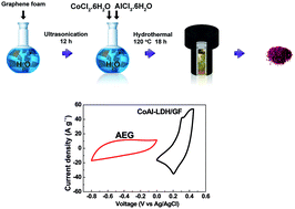
The CoAl-LDH/GF composite was prepared using a hydrothermal reduction technique as shown in Scheme 1. Typically, 25 mg of the as-synthesized graphene foam (GF) was dispersed in 40 mL of water by ultrasonication for 12 h at room temperature. Then CoCl2·6H2O (1.09 g), AlCl3·6H2O (1.2 g) and urea (1.2 g) was added to the pre-sonicated GF solution and the entire mixture was stirred for 10 min. The resulting mixture was then transferred to a Teflon-lined stainless steel autoclave and kept at 120 °C for 18 h. After naturally cooling to room temperature the product CoAl-LDH/GF composite was washed with deionized water and ethanol, and dried at 60 °C for 6 h.


image file: c6ra07419g-s1.tif
Scheme 1 Preparation of CoAl-LDH/GF.

Synthesis of activated carbon from expanded graphite (AEG)

Activated carbon from expanded graphite designated as AEG used for the production of asymmetric device was prepared as reported in our earlier work.46 Briefly expanded graphite and polyvinylpyrrolidonel (PVP) were used as starting material for the production of a hydrogel, which was then used to produce the AEG after the activation process. The activated material was neutralized with 1 M HCl, washed with deionised water and dried at 60 °C for 12 h.

Structure and morphology characterization

Here the characterization was done only for CoAl-LDH and the CoAl-LDH/GF composite since for the AEG sample, all these had already been done and reported in ref. 46 of our earlier work using the same sample. X-ray diffraction (XRD) patterns were collected using an XPERT-PRO diffractometer (PANalytical BV, Netherlands) with theta/2 theta geometry, operating with a cobalt tube at 50 kV and 30 mA. Fourier transform infrared (FTIR) spectra were recorded using a Bruker Vertex 77 v FTIR spectrometer. The morphology was studied using the high-resolution Zeiss Ultra plus 55 field emission scanning electron microscope (FE-SEM) operated at 2.0 kV. Transmission electron microscopy (TEM) micro-images, selected area electron diffraction (SAED) observations and energy dispersive X-ray (EDX) patterns were carried out with a (HRTEM) (Joel JEM-2100F Field Emission Electron Microscope, with a maximum analytical resolution of 200 kV and a probe size under 0.5 nm). The surface area was calculated by the Brunauer–Emmett–Teller (BET) method from the adsorption branch in the relative pressure range (P/P0) of 0.01–1. The pore size distribution of the synthesized materials was studied using Barrett–Joyner–Halenda (BJH) method from the desorption branch of the isotherm nitrogen adsorption–desorption isotherms were measured at −196 °C using a Micromeritics ASAP 2020. All the samples were degassed at 180 °C for more than 12 h under vacuum conditions.

Electrode preparation and electrochemical characterization

The electrochemical measurements were carried out in both three and two electrodes configurations using a Biologic VMP-300 potentiostat (Knoxville TN 37930, USA) controlled by the EC-Lab® V10.37 software. The electrochemical measurements for CoAl-LDH, CoAl-LDH/GF and AEG were performed in a three-electrode configuration using a 6 M KOH electrolyte. The as prepared electrodes served as the working electrodes, Ag/AgCl (3 M KCl) served as the reference electrode and glassy carbon plate as the counter electrode. The AEG and polyvinylidene fluoride (PVDF) binder were mixed in a weight ratio of 9[thin space (1/6-em)]:[thin space (1/6-em)]1 which was homogenized and dispersed in N-methylpyrrolidone (NMP) solution to obtain the slurry, while for the other electrode materials (CoAl-LDH and CoAl-LDH/G), carbon black (CB) (to improve the conductivity) and polyvinylidene fluoride (PVDF) binder were mixed in a weight ratio of 8[thin space (1/6-em)]:[thin space (1/6-em)]1[thin space (1/6-em)]:[thin space (1/6-em)]1 and dispersed in N-methylpyrrolidone (NMP) solution to obtain a slurry. Both slurries from negative and positive electrodes were then uniformly coated on a nickel foam current collector and dried at 60 °C in an oven for 8 h.

The electrochemical test of the asymmetric cell was carried out in a two-electrode cell configuration by means of coin-type cells using a glass micro fiber filter paper as the separator in a 6 M KOH aqueous electrolyte solution with CoAl-LDH/GF and AEG as cathode and anode respectively.

Results and discussion

Fig. 1(a) shows the XRD patterns of the CoAl-LDH and CoAl-LDH/GF composite. The wavelength used for the XRD analysis was the 1.7890 Å line of a Co-Kα source. All diffraction peaks designated in the figure correspond to the pure hydrotalcite structure (JCPDS: 38-0487) with the characteristics peaks of (003), (006), (012), (015) and (018) planes.47,48 The XRD data suggest that CoAl-LDH preferentially grows in the (003) crystallographic direction.
image file: c6ra07419g-f1.tif
Fig. 1 (a) XRD patterns and (b) FTIR spectra of CoAl-LDH and CoAl-LDH/GF composite respectively.

The interlayer spacing between the CoAl-LDH sheets was calculated to be 0.748 nm (d003) indicating the presence of CO32− ions and water molecules occupying the interlayer spaces.49 The XRD peak of graphene was barely identifiable in the CoAl-LDH/GF as shown in the figure because the CoAl-LDH/GF crystals deposited on graphene can prevent graphene from stacking into multilayers leading to lesser crystalline intensity peak of graphene.28 As a result, the weak graphene peak was enshrouded by the stronger CoAl-LDH peaks.

Fig. 1(b) shows the FTIR spectra of CoAl-LDH and CoAl-LDH/GF composite. The absorption peak at wavelength of 3421.6 cm−1 corresponds to the O–H stretching vibration of the interlayer water molecules,48 but the CoAl-LDH/GF composite does not show this absorption peak and that suggest that a presence of graphene in CoAl-LDH breaks the hydrogen bonding that carries the interlayer water molecules. The peaks at 1343.14 and 781.4 cm−1 are due to the ν3 vibration and the bending modes of CO32−.28 The peak below 800 cm−1 is associated with the metal–oxygen (M–O) stretching and bending modes.28,37

The morphology of the material significantly influences the suitability of the material for supercapacitor application. Fig. 2 shows the FESEM microstructures of the as-prepared samples. The morphology of the CoAl-LDH Fig. 2(a) and (b) indicates that the product is formed and mainly composed of thin irregular hexagonal flakes for low and high magnifications respectively. However, in the presence of graphene foam, numerous CoAl-LDH nanosheets were observed to be densely anchored onto graphene as shown in Fig. 2(c) and (d) at low and high magnifications respectively. CoAl-LDH is well dispersed in the graphene matrix which is essential for providing the necessary surface required for efficient charge transport and storage.


image file: c6ra07419g-f2.tif
Fig. 2 Low and high magnification SEM images of (a and b) CoAl-LDH and (c and d) CoAl-LDH/GF respectively.

Fig. 3(a) shows the TEM image of a typical nanosized CoAl-LDH. It can be clearly observed that the LDH samples are nearly hexagonal platelets with a lateral size. The TEM micrograph in Fig. 3(b) shows that the same CoAl-LDH sheets are well dispersed on the surface of graphene sheets. The crystallinity of the as-synthesized CoAl-LDH was further confirmed by selected-area electron diffraction (SAED) pattern as shown in Fig. 3(c), which shows the very high degree of crystallinity of the platelets with a net hexagonal symmetry revealing crystallographic nature of the sample. The corresponding EDX pattern in Fig. 3(d) confirms that a CoAl-LDH/GF composite is composed of three main elements of aluminium, cobalt and carbon atoms in the sample. The element Cu recorded in the spectra is depicted due to the copper grid sample holder for microscopy analysis.


image file: c6ra07419g-f3.tif
Fig. 3 TEM images of (a) CoAl-LDH, and (b) CoAl-LDH/GF, (c) SAED of CoAl-LDH and (d) EDX pattern of CoAl-LDH/GF respectively.

A large surface area and favourable pore size distribution are known to be important factors to advance electrode materials for supercapacitor. The nitrogen adsorption–desorption isotherm of the CoAl-LDH and CoAl-LDH/GF composite show a type III behaviour with a very small H3 hysteresis loops indicating the existence of non-rigid aggregates of plate-like particles or assemblages of slit-shaped pores with no saturation (Fig. 4(a)). Corresponding specific surface areas (SSAs) of. 20.7 m2 g−1 and 187 m2 g−1 were recorded for the CoAl-LDH and CoAl-LDH/GF composite samples respectively. Fig. 4(b) shows the pore size distribution plot in which a concentration of pore volume ranging from 2–4 nm is observed. This suggests that the pores present in these materials are mainly mesopores. The BET results obtained for the CoAl-LDH/GF composite indicates that the sample possesses a larger SSA and micropore/mesopores volume than CoAl-LDH alone. It is clear that CoAl-LDH/GF composite will facilitate the electrolyte ion diffusion, improve the ion transport and provide more electroactive sites for fast energy storage. These features in effect will lead to a correspondingly higher electrochemical performance for the CoAl-LDH/GF.


image file: c6ra07419g-f4.tif
Fig. 4 (a) N2 absorption/desorption isotherms and (b) pore size distribution of CoAl-LDH and CoAl-LDH/GF composite respectively.

Electrochemical performance of CoAl-LDH and AEG

To evaluate the potential applications of the electrode materials for supercapacitor applications, the individual electrochemical properties of the CoAl-LDH, CoAl-LDH/GF composite and the AEG samples were first studied in a three-electrode system using 6 M KOH electrolyte. Cyclic voltammetry (CV), chronopotentiometry (CD) and electrochemical impedance spectroscopy (EIS) measurements were carried out for all samples. Fig. 5(a) shows the CV curves obtained in a three-electrode cell for the CoAl-LDH and CoAl-LDH/GF composite at scan rate of 50 mV s−1 in a potential range of 0.0 to 0.45 V. For the CoAl-LDH and CoAl-LDH/GF samples, two redox peaks corresponding to anodic and cathodic peaks at ∼0.20 V and ∼0.30 V vs. Ag/AgCl are clearly observed showing that the measured capacitance can be attributed to a redox charge storage mechanism. Therefore, the pair of redox peaks were due to the faradic reaction of Co(II)/Co(III) (eqn (1)) and Co(III)/Co(IV) (eqn (2)) respectively.50 The COAl-LDH is denoted as LDH-Co (OH)2 since the Al in this material is an electrochemically inert element.50,51 The anodic/cathodic peaks show the faradic reaction of electrode occurred during the charge–discharge process which is, as a result of the redox reaction and can be written as follows:
 
LDH-Co(OH)2 + OH ↔ LDH-CoOOH + H2O + e (1)
 
LDH-CoOOH + OH ↔ LDH-CoO2 + H2O + e (2)

image file: c6ra07419g-f5.tif
Fig. 5 (a) Cyclic voltammetry comparison at scan rate of 50 mV s−1 and (b) cyclic voltammetry at scan rates of 5–100 mV s−1; (c) galvanostatic charge–discharge comparison at current density of 1 A g−1, (d) galvanostatic charge–discharge at current densities of 1–10 A g−1 and (e) specific capacitance versus current densities of the of CoAl-LDH, CoAl-LDH/GF composite and AEG respectively.

The CoAl-LDH/GF composite also shows similar peaks which have shifted from the initial values when compared to the pure CoAl-LDH sample. This is attributed to the presence of the GF which might induce a shift in the peak positions. Also, the composite displays a better capacitive behaviour as observed by the higher current response. Fig. 5(b) shows the CV curves of the AEG electrodes at various scan rates ranging from 5 to 100 mV s−1. These CV curves display relatively rectangular shapes without redox peaks which are the typical characteristic of electric double-layer capacitive sample behaviour.9 Fig. 5(c) illustrates the overlaid galvanostatic charge–discharge (GCD) curves of the CoAl-LDH and the CoAl-LDH/GF composite at a current density of 1 A g−1 within a potential range of 0–0.45 V respectively. Each discharge curve includes two clear voltage steps: a fast potential drop from 0.40–0.30 V and a voltage plateau from 0.30–0.12 V. The voltage plateau at around 0.3 V suggests a typical faradic characteristic which is in good agreement with the CV curves reported in Fig. 5(a). It can also be clearly seen that the integral area of the cyclic voltammogram and discharge time of the CoAl-LDH/GF composite are large and longer respectively as compared to pristine sample which is the indication of the higher specific capacitance. Fig. 5(d) shows the galvanostatic charge/discharge curves of the AEG electrode at different current densities within a potential range of −0.8 to 0 V. As can be seen from the figure, the shapes of the charge–discharge curves are all nearly symmetrical with a triangular shape which shows a typical electric double-layer capacitive behavior. This is also in agreement with the results from the CV curves in Fig. 5(b). The AEG electrode has a small amount of internal resistance (IR) voltage drop at a current density of 1 A g−1, which is revealed by a rapid potential drop at the very beginning of the discharge process. Based on the galvanostatic charge–discharge (CD) curves, the specific capacitance of the electrode materials was evaluated from the galvanostatic charge–discharge (GCD) curves using eqn (3):

 
image file: c6ra07419g-t1.tif(3)
where I is the discharge current (A), t is the discharge time (s), m is the mass of active material (g), Δv is the potential range of discharge (V), and Cs is the specific capacitance (F g−1).

The specific capacitances of the CoAl-LDH, CoAl-LDH/GF composite and the AEG were calculated at different current densities and the plot of the specific capacitance (F g−1) as a function of current density (A g−1) is shown in Fig. 5(e). The specific capacitance of pristine CoAl-LDH is lower than those of the CoAl-LDH/GF composite. An enhancement in the specific capacitance of the CoAl-LDH/GF composite is due to the addition of porous and conducting graphene foam to the CoAl-LDH matrix which provides an improved electron transfer rate and better structural support for the growth of CoAl-LDH flakes on the graphene sheets. The observed capacitive characteristic observed in the AEG sample is attributed to the presence of the microporous structure in carbon which facilitates rapid electrolyte transfer and relatively high degree of graphitization that provide good electrical conductivity to the electrode.52

Electrochemical properties of the asymmetric supercapacitor

To further assess the practical prospective application of the CoAl-LDH/GF composite with AEG in supercapacitors, an asymmetric device was assembled in which the positive electrode comprised of the CoAl-LDH/GF composite material and the AEG material was used as the negative electrode.

In order to obtain the optimal performance of the asymmetric full cell supercapacitor, the charge balance between the two electrodes should follow the relationship: Q+ = Q, where Q+ and Q are the charges stored in the positive and negative electrodes respectively. The charge stored by each electrode can be expressed as:53

 
Q = Cs × m × ΔU (4)
where Cs is the specific capacitance of the active material, m is the mass of each active material and ΔU is the potential range during the charge–discharge process.

In order to get Q+ = Q, the mass balancing between the negative and positive electrode could also be expressed as follows:

 
image file: c6ra07419g-t2.tif(5)

For making two electrode cells, according to eqn (5), the mass ratio of the CoAl-LDH/GF (positive electrode) to the negative electrode was about 2.3[thin space (1/6-em)]:[thin space (1/6-em)]3.4. Fig. 6(a) shows the CV of the CoAl-LDH/GF and the AEG electrodes at a scan rate of 50 mV s−1 in a three electrode system. From Fig. 6(a), it is expected that the operating cell voltage could be extended up to about 1.4 V if the CoAl-LDH/GF electrode as a cathode and the AEG electrode as an anode are assembled into asymmetric devices in a 6 M KOH electrolyte solution. Fig. 6(b) shows the CV curves of the CoAl-LDH/GF//AEG asymmetric device measured at different scan rates from 5–100 mV s−1. It indicates that the CV curves at different scan rates show an electric double layer capacitance and faradic behaviour which is a typical characteristic of hybrid asymmetric supercapacitors. The charge–discharge curves of the asymmetric supercapacitor at various current densities are shown in Fig. 6(c). It can be seen that the shapes of the charge–discharge curves show non-linearity indicating some contribution from the redox reaction of the CoAl-LDH/GF composite which is in good agreement with the CV curves reported in Fig. 6(b). The specific capacitance of the CoAl-LDH/GF//AEG can also be calculated from eqn (2). The specific capacitance of the asymmetric device decreases from 101 F g−1 to 42 F g−1 with an increase in current density from 0.5 to 5 A g−1 as shown in Fig. 6(d). The Ragone plot for energy density and power density presents two key parameters to characterize the performance of electrochemical supercapacitors. The corresponding energy and power densities of EC can be calculated from the specific capacitance, Cs according to the following equations:

 
image file: c6ra07419g-t3.tif(6)
 
image file: c6ra07419g-t4.tif(7)
where Ed is the average energy density (W h kg−1), Cs is the specific capacitance based on the electroactive material (F g−1), ΔU is the potential window, Pd is the average power density (W kg−1) and t is the discharge time (seconds).


image file: c6ra07419g-f6.tif
Fig. 6 (a) Cyclic voltammetry of CoAl-LDH/GF and AEG electrodes at scan rates of 50 mV s−1 for three-electrode setup; asymmetric CoAl-LDH/GF//AEG device (b) cyclic voltammetry at scan rates of 5–100 mV s−1, (c) galvanostatic charge–discharge at current densities of 0.5–5 A g−1 and (d) the specific capacitance as function of the current density, (e) Ragone plot and (f) cycle stability at a constant current density of 0.5 A g−1 (inset shows charge–discharge curves after 200 circles) respectively.

The Ragone plot showing relationship between energy and power densities of the asymmetric device is shown in Fig. 6(e). The maximum energy density of the device was recorded as 28 W h kg−1 with a corresponding power density of 1420 W kg−1 at a current density of 0.5 A g−1 as shown in Fig. 6(e). The energy density in aqueous electrolyte solution is higher than reported asymmetric supercapacitor, such as NixCo1−x LDH-ZTO//AC (23.7 W h kg−1 and 284.2 W kg−1 at 0.5 g−1),54 CoMn-LDH/Ni foam//AC (energy density of 4.4 W h kg−1 corresponding power density of 2500 W kg−1 at 0.5 A g−1)55 and NiCo2O4-rGO//AC (23.32 W h kg−1 and 324.9 W kg−1 at 0.5 g−1)56 but comparable or smaller than those reported for RGO/CoAl-LDH//AC (energy density of 35.5 W h kg−1 corresponding power density of 8.75 kW kg−1 at 1 A g−1)57 and Ni–Al LDH/CNTs//AC (energy density of 52 W h kg−1 at 1 A g−1).58 However, our electrode material presents a higher and better stability compared to RGO/LDH//AC (90% after 6000 cycles at 4 A g−1) and Ni–Al LDH/CNTs//AC (70.3% after 2000 cycles) materials. The latter already deteriorate after 500 cycles. The long-term stability of the CoAl-LDH/GF//AEG asymmetric device was studied by continuous galvanostatic charge–discharge cycling at a current density of 0.5 A g−1 for 5000 cycles as shown in Fig. 6(f). The capacitance retention of the CoAl-LDH/GF//AEG asymmetric devices after 5000 cycles is 100%, indicating that the device shows good electrochemical stability. The electrode materials are selectively etched in the presence of KOH alkali solution and further activated electrochemically in the cycling process which aids in improving their wettability and these changes allow the trapped electrolyte ions to diffuse out.59

In order to investigate the impedance behaviour at the electrode/electrolyte interface in detail, EIS measurements were employed at an open circuit potential to further evaluate the electrochemical behaviour of the asymmetric device at a frequency range of 10 mHz to 100 kHz. The Nyquist plot for the asymmetric CoAl-LDH/GF//AEG device is shown in Fig. 7(a), with an intercept to x-axis of 0.89 Ω which corresponds to the solution resistance (RS) and was calculated to be 1.2 Ω from the fit to the data using the circuit shown in the inset to the figure. In the circuit the equivalent series resistance, RS is in series with the constant phase element (Q1) representing double layer capacitance, which occur in the interface between material and the electrolyte, and Q1 is connected in parallel with the charge transfer resistant RCT. The leakage current RL is connected in parallel to Q2 element representing double-layer capacitance.


image file: c6ra07419g-f7.tif
Fig. 7 (a) EIS plot and fitting curve for the asymmetric cell, (b) EIS before and after cycling and (c) the real and imaginary part of the cells capacitance against frequency of asymmetric cell of CoAl-LDH/GF//AEG respectively.

Fig. 7(b) shows the Nyquist plots for the CoAl-LDH/GF//AEG asymmetric devices before and after continuous cycling. From the x-axis intercept, RS values of 0.89 Ω and 2.32 Ω were obtained before and after cycling. After 5000 cycles, the electrode shows a larger transfer resistance due to the decomposition of the electrolyte and decrease of electrical conductivity.60

The real (C′(ω)) and imaginary (C′′(ω)) capacitances as a function of frequency are shown in Fig. 7(c). The capacitance of 0.016 F (from topmost part of the C′) was observed which represents the deliverable capacitance as a function of frequency. Furthermore, it is observed that the imaginary capacitance passes through a maximum frequency f0 (0.24 Hz), which is the transition frequency between a pure resistive behaviour and pure capacitive behaviour, and is related to the relaxation time image file: c6ra07419g-t5.tif. This time signifies that the cell could reach its maximum capacitance at a very fast recharging time of 4.3 s. The fast frequency response of 0.24 Hz was attributed to the porous structure of the electrode material which delivers full accessibility to the ions from the electrolyte leading to faster diffusion rates.

Conclusions

In summary, the CoAl-LDH/GF//AEG was investigated as a suitable material for an asymmetric supercapacitor cell based on AEG material as negative electrodes and CoAl-LDH/GF composite as positive electrode. The asymmetrical device exhibited high specific capacitance of 101.4 F g−1 at a current density of 0.5 A g−1 with a maximum energy density of 28 W h kg−1 and a corresponding power density of 1420 W kg−1 in aqueous electrolyte. In addition, an excellent stability with ∼100% capacitance retention with no capacitance loss after 5000 cycles at a current density of 2 A g−1 is attained within an extended operating voltage of about 1.4 V in 6 M KOH aqueous electrolyte. These results demonstrate an optimized hybrid structure applicable in high performance supercapacitors. Finally, these findings offer a suitable and effective way to assemble asymmetric hybrid supercapacitors based on CoAl-LDH/GF composite and AEG with high energy density while sustaining the high power density property of supercapacitor.

Acknowledgements

This work is based on the research supported by the South African Research Chairs Initiative of the Department of Science and Technology and National Research Foundation of South Africa (Grant No. 97994). Any opinion, finding, and conclusion or recommendation expressed in this material are that of the author(s), and the NRF does not accept any liability in this regard. T. M. Masikhwa and M. J. Madito acknowledges the financial support from University of Pretoria and NRF for funding their Ph.D. studies.

References

  1. L. L. Zhang and X. S. Zhao, Chem. Soc. Rev., 2009, 38, 2520–2531 RSC.
  2. H. Wang, Y. Wang, Z. Hu and X. Wang, ACS Appl. Mater. Interfaces, 2012, 4, 6827–6834 CAS.
  3. L. Mei, T. Yang, C. Xu, M. Zhang, L. Chen, Q. Li and T. Wang, Nano Energy, 2014, 3, 36–45 CrossRef CAS.
  4. H. Du, L. Jiao, K. Cao, Y. Wang and H. Yuan, ACS Appl. Mater. Interfaces, 2013, 5, 6643–6648 CAS.
  5. H. Chen, J. Jiang, L. Zhang, H. Wan, T. Qi and D. Xia, Nanoscale, 2013, 5, 8879–8883 RSC.
  6. M. Huang, F. Li, Y. X. Zhang, B. Li and X. Gao, Ceram. Int., 2014, 40, 5533–5538 CrossRef CAS.
  7. J. Zhang, X. Wang, J. Ma, S. Liu and X. Yi, Electrochim. Acta, 2013, 104, 110–116 CrossRef CAS.
  8. W. Lu, P. Soukiassian and J. Boeckl, MRS Bull., 2012, 37, 1119–1124 CrossRef CAS.
  9. G. Wang, L. Zhang and J. Zhang, Chem. Soc. Rev., 2012, 41, 797 RSC.
  10. Z. Gao, W. Yang, J. Wang, B. Wang, Z. Li, Q. Liu, M. Zhang and L. Liu, Energy Fuels, 2012, 27, 568–575 CrossRef.
  11. L. Huang, D. Chen, Y. Ding, S. Feng, Z. L. Wang and M. Liu, Nano Lett., 2013, 13, 3135–3139 CrossRef CAS PubMed.
  12. Q. Chen, H. Li, C. Cai, S. Yang, K. Huang, X. Wei and J. Zhong, RSC Adv., 2013, 3, 22922–22926 RSC.
  13. Y. Li, X. Zhao, P. Yu and Q. Zhang, Langmuir, 2012, 29, 493–500 CrossRef PubMed.
  14. Y. Zhang, H. Feng, X. Wu, L. Wang, A. Zhang, T. Xia, H. Dong, X. Li and L. Zhang, Int. J. Hydrogen Energy, 2009, 34, 4889–4899 CrossRef CAS.
  15. E. Frackowiak, Phys. Chem. Chem. Phys., 2007, 9, 1774–1785 RSC.
  16. L. L. Zhang, R. Zhou and X. S. Zhao, J. Mater. Chem., 2010, 20, 5983 RSC.
  17. J. P. C. Trigueiro, R. L. Lavall and G. G. Silva, Electrochim. Acta, 2016, 187, 312–322 CrossRef CAS.
  18. Y. Jiang, J. Yan, X. Wu, D. Shan, Q. Zhou, L. Jiang, D. Yang and Z. Fan, J. Power Sources, 2016, 307, 190–198 CrossRef CAS.
  19. J. Chen, Y. Cui, X. Wang, M. Zhi, M. Lavorgna, A. P. Baker and J. Wu, Electrochim. Acta, 2016, 188, 704–709 CrossRef CAS.
  20. K. S. Novoselov, V. I. Fal, L. Colombo, P. R. Gellert, M. G. Schwab and K. Kim, et al., Nature, 2012, 490, 192–200 CrossRef CAS PubMed.
  21. A. K. Geim and K. S. Novoselov, Nat. Mater., 2007, 6, 183–191 CrossRef CAS PubMed.
  22. S. Bag and C. R. Raj, J. Mater. Chem. A, 2016, 4, 587–595 CAS.
  23. S. Gao, Y. Sun, F. Lei, L. Liang, J. Liu, W. Bi, B. Pan and Y. Xie, Angew. Chem., Int. Ed., 2014, 53, 12789–12793 CrossRef CAS PubMed.
  24. J. Feng, X. Sun, C. Wu, L. Peng, C. Lin, S. Hu, J. Yang and Y. Xie, J. Am. Chem. Soc., 2011, 133, 17832–17838 CrossRef CAS PubMed.
  25. S. Liu, K. S. Hui, K. N. Hui, V. V Jadhav, Q. X. Xia, J. M. Yun, Y. R. Cho, R. S. Mane and K. H. Kim, Electrochim. Acta, 2016, 188, 898–908 CrossRef CAS.
  26. Y. Juan, Y. Chang, X. Fan, S. Liang, S. Li, H. Huang, Z. Ling, C. Hao and Q. Jieshan, Energy Environ. Sci., 2016, 9, 1299–1307 Search PubMed.
  27. Y. Zhu, C. Cao, S. Tao, W. Chu, Z. Wu and Y. Li, Sci. Rep., 2014, 4, 5787 CrossRef CAS PubMed.
  28. L. Zhang, K. N. Hui, K. San Hui and H. Lee, Electrochim. Acta, 2015, 186, 522–529 CrossRef CAS.
  29. Y. Wimalasiri, R. Fan, X. S. Zhao and L. Zou, Electrochim. Acta, 2014, 134, 127–135 CrossRef CAS.
  30. F. Lai, Y. Huang, Y.-E. Miao and T. Liu, Electrochim. Acta, 2015, 174, 456–463 CrossRef CAS.
  31. K. Krishnamoorthy, G. K. Veerasubramani, S. Radhakrishnan and S. J. Kim, Mater. Res. Bull., 2014, 50, 499–502 CrossRef CAS.
  32. J. H. Han, S. Lee and J. Cheon, Chem. Soc. Rev., 2013, 42, 2581–2591 RSC.
  33. W. Yang, Z. Gao, J. Wang, J. Ma, M. Zhang and L. Liu, ACS Appl. Mater. Interfaces, 2013, 5, 5443–5454 CAS.
  34. A. Zhang, C. Wang, Q. Xu, H. Liu, Y. Wang and Y. Xia, RSC Adv., 2015, 5, 26017–26026 RSC.
  35. Y. Lin, L. Ruiyi, L. Zaijun, L. Junkang, F. Yinjun, W. Guangli and G. Zhiguo, Electrochim. Acta, 2013, 95, 146–154 CrossRef.
  36. L. Zhang, J. Wang, J. Zhu, X. Zhang, K. San Hui and K. N. Hui, J. Mater. Chem. A, 2013, 1, 9046–9053 CAS.
  37. S. Huang, G.-N. Zhu, C. Zhang, W. W. Tjiu, Y.-Y. Xia and T. Liu, ACS Appl. Mater. Interfaces, 2012, 4, 2242–2249 CAS.
  38. L. Wang, D. Wang, X. Y. Dong, Z. J. Zhang, X. F. Pei, X. J. Chen, B. Chen and J. Jin, Chem. Commun., 2011, 47, 3556–3558 RSC.
  39. J. Fang, M. Li, Q. Li, W. Zhang, Q. Shou, F. Liu, X. Zhang and J. Cheng, Electrochim. Acta, 2012, 85, 248–255 CrossRef CAS.
  40. Z. Lin, X. Yan, J. Lang, R. Wang and L.-B. Kong, J. Power Sources, 2015, 279, 358–364 CrossRef CAS.
  41. S. Yang, K. Cheng, K. Ye, Y. Li, J. Qu, J. Yin, G. Wang and D. Cao, J. Electroanal. Chem., 2015, 741, 93–99 CrossRef CAS.
  42. J. Huang, P. Xu, D. Cao, X. Zhou, S. Yang, Y. Li and G. Wang, J. Power Sources, 2014, 246, 371–376 CrossRef CAS.
  43. W. Liu, X. Li, M. Zhu and X. He, J. Power Sources, 2015, 282, 179–186 CrossRef CAS.
  44. Z. Yu, M. McInnis, J. Calderon, S. Seal, L. Zhai and J. Thomas, Nano Energy, 2015, 11, 611–620 CrossRef CAS.
  45. D. Y. Momodu, F. Barzegar, B. Abdulhakeem, J. Dangbegnon, T. Masikhwa, J. Madito, N. Manyala, A. Bello, J. Dangbegnon, T. Masikhwa, J. Madito and N. Manyala, Electrochim. Acta, 2015, 151, 591–598 CrossRef CAS.
  46. F. Barzegar, A. Bello, D. Momodu, M. J. Madito, J. Dangbegnon and N. Manyala, J. Power Sources, 2016, 309, 245–253 CrossRef CAS.
  47. L.-H. Su and X.-G. Zhang, J. Power Sources, 2007, 172, 999–1006 CrossRef CAS.
  48. W. Lin, W. Yu, Z. Hu, W. Ouyang, X. Shao, R. Li and D. S. Yuan, Electrochim. Acta, 2014, 143, 331–339 CrossRef CAS.
  49. L. Zhang, X. Zhang, L. Shen, B. Gao, L. Hao, X. Lu, F. Zhang, B. Ding and C. Yuan, J. Power Sources, 2012, 199, 395–401 CrossRef CAS.
  50. J. Han, Y. Dou, J. Zhao, M. Wei, D. G. Evans and X. Duan, Small, 2013, 9, 98–106 CrossRef CAS PubMed.
  51. E. Scavetta, B. Ballarin, M. Gazzano and D. Tonelli, Electrochim. Acta, 2009, 54, 1027–1033 CrossRef CAS.
  52. K. Wang, N. Zhao, S. Lei, R. Yan, X. Tian, J. Wang, Y. Song, D. Xu, Q. Guo and L. Liu, Electrochim. Acta, 2015, 166, 1–11 CrossRef CAS.
  53. A. Bello, F. Barzegar, D. Momodu, J. Dangbegnon, F. Taghizadeh, M. Fabiane and N. Manyala, J. Power Sources, 2015, 273, 305–311 CrossRef CAS.
  54. X. Wang, A. Sumboja, M. Lin, J. Yan and P. S. Lee, Nanoscale, 2012, 4, 7266–7272 RSC.
  55. A. D. Jagadale, G. Guan, X. Li, X. Du, X. Ma, X. Hao and A. Abudula, J. Power Sources, 2016, 306, 526–534 CrossRef CAS.
  56. X. Wang, W. S. Liu, X. Lu and P. S. Lee, J. Mater. Chem., 2012, 22, 23114–23119 RSC.
  57. W. Zhang, C. Ma, J. Fang, J. Cheng, X. Zhang, S. Dong and L. Zhang, RSC Adv., 2013, 3, 2483–2490 RSC.
  58. M. Li, F. Liu, J. P. Cheng, J. Ying and X. B. Zhang, J. Alloys Compd., 2015, 635, 225–232 CrossRef CAS.
  59. J. Yang, C. Yu, X. Fan and J. Qiu, Adv. Energy Mater., 2014, 4(18) DOI:10.1002/aenm.201400761.
  60. G. Huang, S. Xu, S. Lu, L. Li and H. Sun, ACS Appl. Mater. Interfaces, 2014, 6, 7236–7243 CAS.

This journal is © The Royal Society of Chemistry 2016