Photocatalytic activity of an electrophoretically deposited composite titanium dioxide membrane using carbon cloth as a conducting substrate

Boor Singh Lalia, Corrado Garlisi, Giovanni Palmisano* and Raed Hashaikeh*
Institute Center for Water and Environment (iWater), Masdar Institute of Science and Technology, P.O. Box 54224, Abu Dhabi, United Arab Emirates. E-mail: rhashaikeh@masdar.ac.ae; gpalmisano@masdar.ac.ae

Received 21st March 2016 , Accepted 27th June 2016

First published on 29th June 2016


Abstract

This is the first report where a polymer, namely poly(vinylidene fluoride-co-hexafluoropropylene) (PVDF–HFP), has been used as a binder together with the electrophoretic deposition process. PVDF–HFP provided mechanical stability and membrane flexibility and, at the same time, eliminated the leaching of the electrophoretically deposited TiO2 particles in the solution during the water treatment process. Electrophoretic deposition of TiO2 particles containing different weight percentages of PVDF–HFP were conducted and the required concentration of PVDF–HFP in the solution to prevent the leaching of TiO2 was established. The obtained material finds applications in photocatalytic water treatment, as investigated under simulated solar light in aqueous solutions using 4-nitrophenol, caffeine, acetaminophen and uracil as target molecules. Results indicated the complete removal of 4-nitrophenol after 24 hours, a degradation percentage above 80% of acetaminophen and uracil and 60% for caffeine. Photodegradation of pre-adsorbed methylene blue (MB) both under simulated solar radiation and visible light was successfully achieved in dry conditions as confirmed by diffusion reflectance spectra.

1. Introduction

Industrial development in the recent decades has led to water pollution problems becoming more and more severe. Membrane separation technology is one of the viable solutions to waste water treatment compared to the traditional chemical treatment. Titanium dioxide has attracted the scientific community because of its photocatalytic activity to decompose organic chemicals and kill bacteria.1–3 Many organic pollutants in wastewater such as alcohols, phenols, dyes, and carboxylic acids can be photodegraded by TiO2 nanoparticles under UV or visible light irradiation.4 Due to the small particle sizes of the TiO2, one major issue is to remove the titanium dioxide from the solution after its use and recycle it.

To solve this issue, TiO2 particles have been embedded in various polymer matrices/inorganic materials to fabricate free standing photocatalytic membranes. Damodar et al. prepared TiO2 entrapped PVDF membrane and studied its antibacterial and photocatalytic properties.5 Dzinun et al. immobilized the TiO2 particles in PVDF hollow fiber membranes and used it for removing nonylphenol in water.6 Zeng et al. prepared TiO2/cellulose composite films by a sol–gel method, where tetrabutyl titanate, precursor of TiO2 particles, was adsorbed on the hydroxylated cellulose followed by the hydrolysis to embed nanoparticles in the cellulose matrix.7

In another approach, Balasubramanian et al. immobilized sol–gel derived TiO2 particles on stainless steel substrates and used them to degrade the 4-chlorobenzoic acid as a model organic compound.8 Khataee et al. immobilized TiO2 nanoparticles on glass substrates and studied the photodegradation of textile dyes on TiO2 nanoparticles.9 In these approaches, the control of thickness of the TiO2 layer on the substrate is limited. At the same time, the exposed surface area of the TiO2 is reduced due to the encapsulation of the substrate to the TiO2 particles as a result of the fabrication process, thus limiting the global activity of the photocatalyst. Combining the photocatalytic functionality with the membrane technology is attractive, however existing fabrication processes produce membranes with embedded particles and the photocatalytic activity of these particles is reduced by the partial exposure to light radiation.

In this work, we propose the use of electrophoretic deposition of TiO2 particles on the surface of carbon cloth to fabricate flexible TiO2-functionalized membranes. The electrophoretic deposition technique has been used before to form thin films of metal oxides in applications such as lithium batteries, dye sensitized solar cells and sensors.1–3,10 To the best of our knowledge, this is the first study dealing with fabrication of flexible and mechanically stable TiO2-functionalized membranes electrophoretically deposited on carbon cloth.

The photocatalytic activity of the fabricated membranes was assessed by means of oxidation runs in liquid phase under solar simulated solar light using caffeine, paracetamol, 4-nitrophenol and uracil as target pollutants. Caffeine (CF) is a purine-based alkaloid extensively consumed either for beverages or medical purposes and personal care products. It is introduced constantly into the natural watercourses through anthropogenic sources and tends to persist in water due to its high solubility and low volatility.11,12 Paracetamol (PAM) is a widespread pharmaceutical product owing to its use as antipyretic and analgesic drug. PAM is ubiquitous in the natural environment and easily accumulates in waters, wastewaters, and drinking water all over the word.13 4-Nitrophenol (4NP) is applied in agriculture, pharmaceuticals and dyes. It is difficult to purify 4NP-contaminated water because of its significant stability to chemical and biological abatement. It takes long time to perform its degradation in ground water and deep soil,14 and it is one of the 114 organic pollutants listed by EPA in USA, with maximum allowed concentration of 20 ppb.15 The reactivity towards biomolecules was also investigated through the photo-oxidation of uracil (UR) that is one of the fundamental components of RNA, in which it forms base pairs with adenine. As a pyrimidine derivatives, UR is present in continental water and can be used for drug delivery and as a pharmaceutical.16 The photocatalytic properties of the membranes were also investigated in dry conditions by the photodegradation of methylene blue (MB) under both simulated solar and visible radiation. This compound is extensively used in textile industry for dyeing cotton wool, and silk.17 MB can cause several problems when it is discharged in the environment due to its harmful effects on human beings and aquatic life since the colored wastewater prevents light penetration.18

It is worth stressing that the radiation used during the runs was provided by either solar simulator or visible lamp in the attempt to induce photochemical reaction in a sustainable way. Indeed, visible radiation constitutes the most abundant part of solar light and the only existing radiation indoors.

2. Experimental

2.1 Materials

Titanium dioxide anatase, iodine, acetone, 4-nitrophenol, uracil, and methylene blue were purchased from Sigma-Aldrich and used as received. Carbon cloth, which was used as substrate, was procured from MTI (USA).

2.2 Membrane fabrication

Composite membranes containing TiO2 nanoparticles deposited on carbon cloth were prepared using the electrophoretic deposition technique, using PVDF–HFP as polymeric binder. For simplicity reasons, the prepared samples will be referred as TiO2/PVDF–HFP membranes. A macroporous carbon cloth was used as cathode material and aluminum foil used as an anode. In the first solution, a dispersion of anatase titanium dioxide (TiO2) was prepared in acetone using iodine as a charging solution. For the preparation of the dispersion, first 80 mg of iodine was dissolved in 100 mL acetone and then 1 g of anatase powder was added to the solution, an ultrasound treatment following for 10 minutes by using a probe sonicator (Hielscher, UP400S, 400 W, 24 kHz) at 50% amplitude and 0.5 cycle to obtain a homogeneous suspension. A second solution containing different weight percent of PVDF–HFP, varying from 10 to 30 wt%, was added in the first solution for the electrophoresis process. A dc potential of 100 V was applied between the carbon cloth as anode and aluminum foil as cathode dipped in the solution using dc power supply (Thermo Scientific, EC 200XL). The potential was applied for 10 minutes and a current of ∼100 mA flowed through the electrophoretic cell. After the deposition, TiO2-coated carbon cloth was removed from the cell and dried at room temperature to achieve acetone evaporation. Then, TiO2/PVDF–HFP coated membrane was placed in an oven at 160 °C to bind the PVDF–HFP coated TiO2 particles.

2.3 Characterization

The electrophoretically deposited TiO2 and TiO2/PVDF–HFP membranes were examined by scanning electron microscopy. A Nova Nanos SEM by FEI (Hillsboro, OR, USA) operating at 10–30 kV was employed in this study. The deposition of a titanium dioxide film was observed by the SEM imaging technique. Distribution of the constitutive elements of the membrane was investigated using a distribution mapping technique by energy dispersive X-ray spectroscope (EDS) combined with SEM. X-ray energies corresponding to titanium, carbon and fluorine were collected as the SEM scanned the electron beam over the membrane cross-section. Z-Potential of the TiO2/PVDF–HFP membrane in a KCl electrolyte solution was measured using an electrokinetic analyzer for solid surfaces analysis (SurPASS™, Anton Paar). A Capillary Flow Porometer (PMI, Ithaca, USA) was used to calculate the mean pore size and pore size distribution of the membranes, and a detailed procedure can be found elsewhere.19 The wet/dry flow method was used during the measurements, a low surface tension wetting liquid (Galwick™) was used to wet the sample first and then placed in a sealed chamber connected to a pressure controlled dry air cylinder. The pressure of the gas increased stepwise on one side of the membrane and the gas flow through the membrane was recorded on the other side of the membrane. There was no flow at the beginning because all the pores were blocked by the wetting liquid. When the pressure reached a sufficient value to remove the liquid from the largest pores, the flow started to increase from its 0 value and it could be recorded. By further increasing the gas pressure, smaller pores became unblocked and the gas flow rate increased until the whole sample became dry. The cumulative pressure needed for gas flow through the wet sample was used to calculate pore diameters.

Tensile testing of the membranes were studied by Instron (Model No. 5982), equipped with a load cell of 5 kN at a strain rate of 1 mm min−1. The dog-bone shaped specimens, having lengths of 65 mm, were cut from the samples. Three samples for each composition were tested to ensure the reproducibility of the test results. XRD analysis of the samples were conducted on PANalytical, Empyrean using 45 kV potential and 40 mA current in the 10–70° (2-theta) range.

The photocatalytic activity of the TiO2/PVDF–HFP membrane was assessed using CF, PAM, 4NP and UR as a target pollutants in water with a concentration of 1 ppm. A continuously stirred cylindrical beaker (volume: 400 mL; diameter: 7.5 cm) containing 250 mL aqueous solution was used as the photoreactor. This latter was equipped with a 0.8 mm thick Teflon plate having a diameter of 7.2 cm and located at 2.5 cm above the bottom of the beaker. During the test, membranes were placed on the above cited Teflon holder provided with 2 mm holes in order to keep the reacting mixture stirred as uniform as possible and to allow oxygen to be properly sparged in the solution (Fig. 1). The photoreactor was irradiated from the top by using a solar simulator (LOT Quantum Design LS0606), equipped with a 1000 W Xenon short arc lamp and an AM1.5 G filter. The average values of the radiation were 9.2 and 740 W m−2 in the ranges 315–400 and 450–950 nm, respectively, measured with a Delta Ohm 9721 radiometer and the matching probes. All the experiments were carried out at room temperature. Before the photocatalytic reaction, the solution was bubbled with O2 and magnetically stirred in the dark for 15 min in order to establish adsorption/desorption equilibrium. During the runs, oxygen was continuously bubbled in the solution and samples were withdrawn at scheduled time intervals (2, 5, 9, 24 hours). After immediate filtration through a PVDF membrane with pore size 0.2 μm they were analyzed.


image file: c6ra07390e-f1.tif
Fig. 1 Scheme (left) and picture (right) of the photoreaction system used during the reactivity tests.

Quantitative determination of the compounds present in the reacting solution were performed by means of a Thermo Scientific HPLC (Dionex UltiMate 3000 Photodiode Array Detector), equipped with a Acclaim-120C18 Reversed-phase LC column working at 25 °C. The injection volume was 10 μL. Table 1 summarizes mobile phases, detection wavelengths and flow rates used for the different chemical compounds.

Table 1 Mobile phases, detection wavelengths and flow rates used over the different runs
Target pollutants Mobile phase (isocratic) Detection wavelength (nm) Flow rate (mL min−1)
Water (%v/v) Acetonitrile (%v/v) Methanol (%v/v) 40 mM KH2PO4 (%v/v) 2 M NH4Ac (%v/v)
CF 10 90 273 0.2
PAM 10 90 245 0.2
4NP 33 33 34 315 0.2
UR 30 69 1 254 0.4


Photocatalytic properties were also evaluated in the oxidation of MB pre-adsorbed on the membranes. The latter were dipped for 12 h in an aqueous solution of 0.6 g L−1 MB to produce saturated adsorption on the membrane surface. After that, the sample was irradiated by simulated solar light with the same average values of radiation used in liquid-phase tests. Runs were also performed under visible LED source with the following characteristic: power absorption: 33 W, emission range: 408–765 nm, radiation intensity reaching the films: 410 W m−2 (measured in the 450–950 nm range). A UV/vis spectrophotometer (Shimadzu UV-2600) was used to determine the discoloration over time by exploring the change in the diffuse reflectance of the membrane around the wavelength of 665 nm, which is the maximum of optical absorption from MB in the visible region.

3. Results and discussion

Electrophoretic deposition of titanium dioxide on the carbon cloth is illustrated in Fig. 2. The solution contains 30 wt% PVDF–HFP polymer used as binder for the membrane. However, the amount of PVDF–HFP in the TiO2 membrane was evaluated by using thermo-gravimetric analysis (TGA) and results are shown in Fig. 2b. When a dc potential is applied between the two electrodes, the charged TiO2 particles are transported through the polymeric solution, thus resulting in the formation of very thin layer of PVDF–HFP on the surface of the titania particles deposited on the carbon cloth. After the deposition process, the samples were heated up to 160 °C, above the melting point of PVDF–HFP, so that the thin layer on the particles binds together and provides the mechanical stability to the membranes.
image file: c6ra07390e-f2.tif
Fig. 2 (a) Illustration showing electrophoretic deposition process used for fabrication of TiO2/PVDF–HFP carbon cloth and (b) thermo-gravimetric (TGA) analysis of deposited membranes.

TGA results reveal that PVDF–HFP contents in the electrophoretically deposited membrane was 8.5 wt%.

Fig. 3a shows the SEM image of the carbon cloth used as substrate to electrophoretic deposition process. Fig. 3b represents the SEM image of pristine TiO2 particles deposited on the carbon cloth. It seems to be very thick and found to be brittle in nature as shown in the Fig. 3b. Fig. 3c shows the SEM images of the TiO2/PVDF–HFP deposited on the carbon cloth. Under similar deposition conditions, TiO2/PVDF seems to be deposited on the carbon cloth uniformly.


image file: c6ra07390e-f3.tif
Fig. 3 SEM images of (a) the carbon cloth, (b) pristine TiO2 membrane, (c) TiO2/PVDF–HFP membrane and (d and e) high resolution images of TiO2/PVDF–HFP membrane.

Fig. 3d and e show high resolution images of TiO2/PVDF–HFP membrane. They show that porous layer of PVDF–HFP is present on the surface of TiO2 particles. This porous layer is formed when the TiO2/PVDF–HFP membrane is taken out of the deposition bath and highly volatile acetone evaporate from the membrane leads to the precipitation of polymer by a well-known process called evaporation-induced phase inversion.20

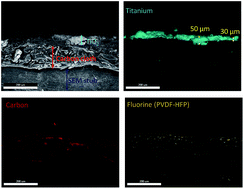
Fig. 4 shows cross-sectional EDS mapping of Ti, C and F. As depicted in Fig. 4b and c the thickness of the TiO2 layer is in the range 30–50 μm whereas the carbon cloth is around 150–170 um. Fluorine, representative of the binder used to prepare the membrane is also present and appears well dispersed on the carbon cloth (Fig. 4d).


image file: c6ra07390e-f4.tif
Fig. 4 Cross-sectional SEM micrograph of TiO2/PVDF–HFP membrane (a) and EDS maps of titanium (b), carbon (c) and fluorine (PVDF–HFP) (d). The scale bar is 200 μm.

X-ray diffraction (XRD) analysis of the starting material, i.e. commercial TiO2 anatase, and as prepared membrane was conducted to check the structural changes, if any, during the electrophoretic deposition process. XRD results are shown in Fig. 5a. The results shows the characteristics peaks of anatase TiO2 phase presented in the diffractogram. It was found that the electrophoretic deposition process does not alter the phase of anatase TiO2 particles.


image file: c6ra07390e-f5.tif
Fig. 5 (a) X-ray diffractogram of as prepared membrane and materials used for the fabrication, (b) tensile stress vs. strain behavior of the TiO2/PVDF–HFP membrane compared with the carbon cloth.

Mechanical behavior of the TiO2/PVDF–HFP membrane was studied by tensile test measurements and results are shown in Fig. 5b. Stress vs. strain behavior of carbon cloth shows that, beyond 0.17 mm mm−1 strain, the curve shows multiple peaks after the first break point. This is due to the fact that carbon cloth is made up of woven carbon fibers as shown in Fig. 3a. When the load is applied, no sudden failure occurs. The strands of the carbon cloth break one by one and during each break one maximum appears in the stress/strain curve. When the load is transferred from the broken strand, the stress will be transferred to the matrix hence the curve shows a sudden drop.

The load will continue to be transferred to the unbroken strands, and by virtue of this another maximum appears in the curve. Same behavior was observed for the TiO2/PVDF–HFP coated carbon cloth. Qualitative analysis of the stress/strain behavior indicates that coating of TiO2/PVDF–HFP on the carbon cloth improves the tensile modulus of the membrane. The tensile strength of the carbon cloth improved from 5.3 MPa to 7.4 MPa. The improvement in mechanical behavior is due to TiO2/PVDF–HFP coating on the fibers and matrix of the carbon cloth.

Leaching out experiments in water were performed by using the pristine TiO2 and TiO2/PVDF–HFP membranes containing 10, 20 and 30 wt% of PVDF–HFP to evaluate the leaching of the TiO2 particles from the membrane. Optical pictures of the samples dipped in water after 24 hours are shown in Fig. 6. Leaching tests on pristine TiO2 membrane dipped in DI water for 24 hours show that TiO2 leaches out quickly on contact with water. However, membrane containing TiO2 and 30 wt% PVDF–HFP was found to be stable in the aqueous conditions. It was noted that a minimum 30 wt% PVDF–HFP is required in the depositing solution to avoid the leaching of TiO2 particles from the membrane. PVDF–HFP is a hydrophobic polymer and by using as a binder it imparts hydrophobicity to the TiO2/PVDF membrane which assist the TiO2 particles to stick together on the membrane.


image file: c6ra07390e-f6.tif
Fig. 6 Stability of TiO2/PVDF–HFP and TiO2 membrane in water.

Pore size distribution (Fig. 7) of the TiO2 membrane with and without PVDF–HFP membrane with different concentration of PVDF was studied. The mean pore size of the TiO2 membrane found to be ∼0.3 microns and of the TiO2/PVDF–HFP was ∼0.28 microns. The pore size distribution revealed that pore size of the TiO2/PVDF–HFP membrane is in the range of microfiltration membrane.


image file: c6ra07390e-f7.tif
Fig. 7 Pore size distribution of the electrophoretically deposited (a) TiO2 pristine membrane and (b) TiO2/PVDF–HFP membrane.

Fig. 8 shows the zeta potential vs. pH curve of the TiO2/PVDF membrane. The IEP (isoelectric point) was at 8.16, which is higher compared to the value of 4.2 reported in literature for anatase (Sigma Aldrich). Notably, the surface of free nanoparticles is charged differently at pH's close to the neutral. This difference may be ascribed to the influence of PVDF–HFP used as binder, determining a positive charge in a more extended pH range.


image file: c6ra07390e-f8.tif
Fig. 8 Zeta potential of the TiO2/PVDF–HFP membrane.

In the evaluation of the photocatalytic properties of the prepared materials, it was preliminary verified that the used compounds were stable in O2-saturated aqueous solution without any applied irradiation. On the contrary, photocatalytic oxidation of CF, PAM, 4NP, and UR under simulated solar light occurs and the resulting degradation is highlighted in Fig. 9. It can be seen from the blank experiment performed on the bare carbon cloth, that all the target molecules, with the exception of uracil, are to some extent degraded in the absence of TiO2 due to a limited photolysis21 or to some photocatalytic activity of the bare carbon cloth. For instance, in the case of 4NP, the conversion is ca. 50% after a reaction time of 24 hours. The reactivity of bare carbon cloth toward the target molecules used can arise from oxygen impurities on the carbon fiber surfaces acting as color centers or, alternatively, from the defect sites, mainly radicals with sp3-hybridized carbon atoms, acting as reaction centers.22 When the TiO2/PVDF–HPF membrane is irradiated, the photogenerated holes electrons can react with surface OH groups to produce extremely reactive radicals such as ˙OH, whereas electrons interact with O2, which is an electron acceptor to produce O2−. These reactive species can oxidize the target molecules to H2O, CO2 and mineral end-products. In any case, the presence of TiO2 improves significantly the photo-oxidation process resulting in the complete abatement of 4NP and 60% and 85% conversion of CF and PAM. With regard to CF, the reaction mechanism involves the breaking of the C4[double bond, length as m-dash]C5 double bound and the consequent reaction with ˙OH to form intermediates species which is rather fast in comparison with the next step involving the complete mineralization of intermediate species such as (N-hydroxymethyl)parabanic acid.23 The presence of reaction intermediates was confirmed by HPLC chromatograms. The photocatalytic oxidation of PAM by TiO2 and UV-vis irradiation is generally a more highly efficient process that involves the formation of p-aminophenol and 4NP24 as intermediates finally converted into CO2. As far as 4NP is concerned, the degradation of phenolic compounds by TiO2 have been investigated extensively.25,26 Nitrophenols normally undergo hydroxylation of the aromatic ring yielding dihydoxynitrobenzene isomers with and the generation of nitrite ions in the early stage of the process followed by the formation of nitrate and ammonium ions.27,28 The higher degradation rates of 4NP may also occur from the good adsorptive capabilities of carbon fiber, albeit not activated, for phenolic compound29 with a consequent facilitation of the photooxidation process. Almost 50% 4NP degradation under UV irradiation has been reported after 8 hours for photocatalytic membranes formed by high surface area TiO2 catalyst, dispersed into polyacrylonitrile.30 However a direct comparison is not possible because of the different kind of applied radiation.


image file: c6ra07390e-f9.tif
Fig. 9 Photolytic (blank) and photocatalytic (TiO2/PVDF–HFP) degradation of caffeine (a), acetaminophen (b), 4-nitrophenol (c) and uracil (d). The blank experiment refers to bare carbon cloth.

As far as UR is concerned, it was degraded by 80% solely thanks to the photo-induced oxidation power TiO2. A modest number of studies have been conducted to determine the reaction mechanism of UR on TiO2 under UV/vis irradiation, that goes through the attack on the C5[double bond, length as m-dash]C6 double bond by ˙OH and subsequent generation of uracil glycol and some isomeric radicals.31

The photocatalytic activity of the TiO2/PVDF–HFP membrane was also explored in dry conditions using preadsorbed MB as a target molecule and monitoring the diffuse reflectance spectra over time (Fig. 10). Runs were carried out both under visible and simulated solar light. After irradiation under visible light for 24 hours, the spectrum reverted back to its original form, indicating that the adsorbed MB molecules were removed. Allegedly the MB degradation takes place through a photosensitized process arising from electron injection into the conduction band of TiO2 following the absorption of visible light from MB. Photodegradation is then supported by a series of oxidizing species such as O2˙.32 Predictably, in the presence of simulated solar light, the kinetic of degradation is much faster resulting in MB removal after only 2 h, due to the direct excitation of TiO2 resulting from ultraviolet radiation present in the solar spectrum. The high efficiency of TiO2/carbon cloth membranes in dye removal has already been reported for rhodamine B photodecomposition under UV light.33 Also here, the excellent adsorption capacity is enhanced by high porosity of the carbon cloth which greatly facilitates the retention and subsequent abatement of pollutants in treatment of wastewater.


image file: c6ra07390e-f10.tif
Fig. 10 Diffusion reflectance spectra of as-prepared TiO2/PVDF–HFP membrane (no MB) and with adsorbed MB over irradiation time. Photocatalytic degradation was performed under visible light (a) and simulated solar light (b).

As shown in Fig. 11, the discoloration of MB after the test was evident leading the membrane to almost recover its original appearance.


image file: c6ra07390e-f11.tif
Fig. 11 TiO2/PVDF–HFP membrane: as-prepared (a), after adsorption of MB (b), after MB degradation (c) in the test performed under visible irradiation.

4. Conclusion

Novel flexible TiO2/PVDF–HFP/carbon membranes were fabricated by the electrophoretic deposition process. The developed process demonstrated that the use of a polymeric binder such as PVDF–HFP can efficiently improve the mechanical stability and flexibility of the fabricated membranes. Pore size measurements indicate that the mean pore size is in the range of ∼0.28 micrometer, which means that the developed membranes can function as microfiltration membranes and at the same time photocatalytic degradation of organic compounds. The coating of TiO2/PVDF–HFP on the carbon cloth improves its mechanical properties and the thickness of the TiO2 layer is around 30–50 μm, as confirmed by the EDS mapping. Photocatalytic properties were explored in liquid phase under simulated solar light and the results were encouraging. 4-Nitrophenol was the target molecule showing the highest degradation rate, total conversion occurred after 24 hours. The conversion for caffeine and paracetamol were 60% and 85% respectively. Uracil was degraded by 80% without any photolysis phenomena or contribution deriving from the bare carbon cloth. Photo-oxidation of pre-adsorbed methylene blue was effectively carried out in dry conditions as confirmed by diffusion reflectance spectra, resulting in its complete degradation after 2 and 24 hours under simulated solar light and visible light, respectively. The novelty of this work is in the technique used for the first time to functionalize carbon cloth with TiO2/PVDF–HFP membrane, in addition to the excellent catalytic activity of the developed membranes. This can be a landmark to develop new class of membrane systems for water treatment applications such as continuous flow membrane reactors.

Acknowledgements

The authors would like to thank Dr Linda Zou for having performed Z-potential measurement.

References

  1. H. Tong, S. Ouyang, Y. Bi, N. Umezawa, M. Oshikiri and J. Ye, Adv. Mater., 2012, 24, 229–251 CrossRef CAS PubMed.
  2. L. Djafer, A. Ayral and A. Ouagued, Sep. Purif. Technol., 2010, 75, 198–203 CrossRef CAS.
  3. S. Anandan, Y. Ikuma and K. Niwa, Solid State Phenom., 2010, 162, 239–260 CrossRef CAS.
  4. R. J. Tayade, R. G. Kulkarni and R. V. Jasra, Ind. Eng. Chem. Res., 2006, 45, 922–927 CrossRef CAS.
  5. R. A. Damodar, S.-J. You and H.-H. Chou, J. Hazard. Mater., 2009, 172, 1321–1328 CrossRef CAS PubMed.
  6. H. Dzinun, M. H. D. Othman, A. F. Ismail, M. H. Puteh, M. A. Rahman and J. Jaafar, Chem. Eng. J., 2015, 269, 255–261 CrossRef CAS.
  7. J. Zeng, S. Liu, J. Cai and L. Zhang, J. Phys. Chem. C, 2010, 114, 7806–7811 CAS.
  8. G. Balasubramanian, D. D. Dionysiou, M. T. Suidan, I. Baudin and J.-M. Laîné, Appl. Catal., B, 2004, 47, 73–84 CrossRef CAS.
  9. A. Khataee, M.-N. Pons and O. Zahraa, J. Hazard. Mater., 2009, 168, 451–457 CrossRef CAS PubMed.
  10. T. Miyasaka and Y. Kijitori, J. Electrochem. Soc., 2004, 151, A1767–A1773 CrossRef CAS.
  11. I. Dalmázio, L. S. Santos, R. P. Lopes, M. N. Eberlin and R. Augusti, Environ. Sci. Technol., 2005, 39, 5982–5988 CrossRef.
  12. R. R. Marques, M. J. Sampaio, P. M. Carrapiço, C. G. Silva, S. Morales-Torres, G. Dražić, J. L. Faria and A. M. Silva, Catal. Today, 2013, 209, 108–115 CrossRef CAS.
  13. M. J. N. Gotostos, C. C. Su, M. D. G. De Luna and M. c. Lu, J. Environ. Sci. Health, Part A: Environ. Sci. Eng., 2014, 49, 892–899 CrossRef CAS PubMed.
  14. G. Palmisano, V. Loddo, H. H. El Nazer, S. Yurdakal, V. Augugliaro, R. Ciriminna and M. Pagliaro, Chem. Eng. J., 2009, 155, 339–346 CrossRef CAS.
  15. D. Chen and A. K. Ray, Water Res., 1998, 32, 3223–3234 CrossRef CAS.
  16. C. Jaussaud, O. Païssé and R. Faure, J. Photochem. Photobiol., A, 2000, 130, 157–162 CrossRef CAS.
  17. M. Berrios, M. Á. Martín and A. Martín, J. Ind. Eng. Chem., 2012, 18, 780–784 CrossRef CAS.
  18. H. Valdés, R. Tardón and C. Zaror, Environ. Technol., 2012, 33, 1895–1903 CrossRef PubMed.
  19. B. S. Lalia, E. Guillen-Burrieza, H. A. Arafat and R. Hashaikeh, J. Membr. Sci., 2013, 428, 104–115 CrossRef CAS.
  20. B. S. Lalia, V. Kochkodan, R. Hashaikeh and N. Hilal, Desalination, 2013, 326, 77–95 CrossRef CAS.
  21. J.-W. Shi, H.-J. Cui, J.-W. Chen, M.-L. Fu, B. Xu, H.-Y. Luo and Z.-L. Ye, J. Colloid Interface Sci., 2012, 388, 201–208 CrossRef CAS PubMed.
  22. Y. Luo, K.-D. Kim, H.-O. Seo, M.-J. Kim, W. S. Tai, K.-H. Lee, D.-C. Lim and Y.-D. Kim, Bull. Korean Chem. Soc., 2010, 31, 1661–1664 CrossRef CAS.
  23. M. Krivec, K. Žagar, L. Suhadolnik, M. Čeh and G. Dražić, ACS Appl. Mater. Interfaces, 2013, 5, 9088–9094 CAS.
  24. E. Moctezuma, E. Leyva, C. A. Aguilar, R. A. Luna and C. Montalvo, J. Hazard. Mater., 2012, 243, 130–138 CrossRef CAS PubMed.
  25. A. Sclafani, L. Palmisano and E. Davi, J. Photochem. Photobiol., A, 1991, 56, 113–123 CrossRef CAS.
  26. N. San, A. Hatipoǧlu, G. Koçtürk and Z. Çınar, J. Photochem. Photobiol., A, 2001, 139, 225–232 CrossRef CAS.
  27. A. Di Paola, V. Augugliaro, L. Palmisano, G. Pantaleo and E. Savinov, J. Photochem. Photobiol., A, 2003, 155, 207–214 CrossRef CAS.
  28. V. Augugliaro, M. López-Mun, L. Palmisano and J. Soria, Appl. Catal., A, 1993, 101, 7–13 CrossRef CAS.
  29. E. Ayranci and O. Duman, J. Hazard. Mater., 2005, 124, 125–132 CrossRef CAS PubMed.
  30. N. Phonthammachai, E. Gulari, A. Jamieson and S. Wongkasemjit, Appl. Organomet. Chem., 2006, 20, 499 CrossRef CAS.
  31. M. Dhananjeyan, R. Annapoorani and R. Renganathan, J. Photochem. Photobiol., A, 1997, 109, 147–153 CrossRef CAS.
  32. J. Zhao, K. Wu, T. Wu, H. Hidaka and N. Serpone, J. Chem. Soc., Faraday Trans., 1998, 94, 673–676 RSC.
  33. L. Yang, Z. Hong, J. Wu and L.-W. Zhu, RSC Adv., 2014, 4, 25556–25561 RSC.

This journal is © The Royal Society of Chemistry 2016
Click here to see how this site uses Cookies. View our privacy policy here.