Diketopyrrolopyrrole-based polymer with a semi-fluorinated side chain for high-performance organic thin-film transistors

Kangjian Miao a, Gil Jo Chaeb, Xiaoxue Wuc, Qinghai Shu*c, Xin Zhua, Bangjin Suna, Jian Fan*a and Shinuk Cho*b
aJiangsu Key Laboratory for Carbon-Based Functional Materials & Devices, Institute of Functional Nano & Soft Materials (FUNSOM), Collaborative Innovation Center of Suzhou Nano Science and Technology, Soochow University, Suzhou, Jiangsu 215123, China. E-mail: jianfan@suda.edu.cn
bDepartment of Physics and EHSRC, University of Ulsan, Ulsan 680-749, Republic of Korea. E-mail: sucho@ulsan.ac.kr
cSchool of Material Science and Engineering, Beijing Institute of Technology, 100081 Beijing, China. E-mail: qhshu121@bit.edu.cn

Received 29th February 2016 , Accepted 11th March 2016

First published on 15th March 2016


Abstract

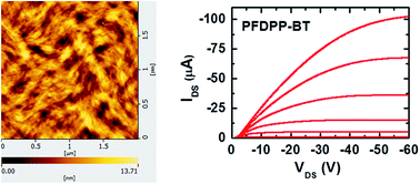
A diketopyrrolopyrrole (DPP) unit with a semi-fluorinated side chain was copolymerized with bithiophenyl (BT) to afford a novel donor–acceptor (D–A) conjugated polymer PFDPP–BT (FDPP refers to the semi-fluorinated DPP unit). The non-fluorinated polymer PDPP–BT was synthesized as the reference polymer to investigate the effect of fluorination of side chains on the morphology of thin films and charge-carrier mobility. Organic thin-film transistors based on these two polymers showed decent device performance. Interestingly, the semiconductor polymer PFDPP–BT exhibited hole mobility about 3 times higher than that of the related PDPP–BT. Atomic force microscopy (AFM) and X-ray diffraction (XRD) measurements demonstrated that the semi-fluorinated side chains had a great effect on the thin film morphology and crystallinity, which led to enhancement in device performance.

Introduction

Since Koezuka and coworkers reported the first organic field-effect transistor (OFET) based on poly-thiophene in 1987,1 there has been a tremendous improvement in terms of the fundamental understanding of the charge injection/transport mechanism, device fabrication and materials development.2–8 During last decade OFETs have attracted much attention because they shows a wide range of applications in active matrix devices and high-speed flexible circuits, such as organic light-emitting diodes (OLEDs), radiofrequency identification tags and flexible electronic sensors.9–11 So far the donor–acceptor conjugated polymer has been the mainstream OFET materials since the intramolecular charge transfer through the donor–acceptor interaction could favor the charge carrier transport. Moreover, the intermolecular donor–acceptor interaction is an important driving force behind the long-range ordering and strong π-stacking of polymeric chain within the thin film.12,13 The donor units applied in the D–A polymers are mainly the furan/thiophene/selenophene derivatives, and the most popular acceptor units such as diketopyrrolopyrrole,14–20 isoindigo,21–23 thienoisoindigo,24–26 benzothiadiazole27,28 and benzobisthiadiazole29,30 have been successfully developed for the optimization of D–A structures.

The development of OFET polymer materials principally involves the design and synthesis of conjugated backbones and the side chains. The conjugated backbones determine the frontier orbital energy levels and π-orbital overlap, and the side chains show an important role in governing the morphology and crystallinity of thin film.17 Side-chain engineering via tuning the branching point away from the polymer backbone will reduce the π-stacking distance and enhance charge carrier transport.31–33 On the other hand, the functionalization of side chain (e.g. siloxane-terminated alkyl chains,22,34,35 oligo(ethylene glycol) chains36 and per-fluorinated/semi-fluorinated chain37–44) has been investigated to demonstrate its diverse and complex effect on the device performance. Particularly, the decoration of organic semiconductors with fluorinated chain leads to the novel supramolecular structures and interesting properties. For example, by the combination of semifluorinated alkyl side chains with polythiophene backbone, Kim et al. demonstrated a thermally reversible soluble–insoluble conjugated polymer with enhanced transistor performance.37 By the introduction of semifluorinated alkyl side chains into naphthalene diimide-based polymers, Cho and coworkers achieved very high electron mobilities up to 6.50 cm2 V−1 s−1 and with a high on–off current ratio of 105.41 The principal chemical and physical features associated with fluorinated chain are: (1) the fluorophilic interaction can promote close packing through fluorocarbon self-segregation. (2) The closely packed fluorinated chain could obstruct the penetration of water and oxygen, thus elongating the device lifetime. (3) The electronic structure at an interface could be tuned by the aligned dipole moment of fluorinated chain.44

Recently great success has been achieved by the introduction of per-fluorinated/semi-fluorinated chain into organic semiconductors. However, the fluorinated OFET materials have not been well studied compared with alkyl chain modified systems.41 So herein we chose DPP as the electron acceptor for the synthesis of D–A polymer PFDPP–BT (Scheme 1), where each DPP unit was modified with a semi-fluorinated chain. Although DPP based polymers for high performance OFETs have been extensively investigated,13–19,28,35,36,45 the fluorinated/semi-fluorinated DPP based polymeric semiconductors has not yet been explored. Thus this study may open doors to a wide range of prospects for high performance OFETs based on the fluorinated DPP polymers. The related non-fluorinated polymer PDPP–BT was also prepared for the comparison study about the effect of semi-fluorinated/non-fluorinated chain on the device performance of these DPP polymers. The charge carrier mobilities in field-effect transistors are found to increase by up to a factor of 3 for PFDPP–BT.


image file: c6ra05318a-s1.tif
Scheme 1 Synthetic routes of PFDPP–BT and PDPP–BT.

The synthesis of PFDPP–BT and PDPP–BT was depicted in Scheme 1. Initially, each DPP unit decorated by two semi-fluorinated chains was designed and synthesized. However the desired D–A polymer showed very poor solubility in common organic solvent. Thus a branched alkyl chain, 4-tetradecyl-octadecane, was introduced to enhance the solubility of resultant polymer. The relative large linear space group C4 of this branched alkyl group would be helpful to reduce the steric hindrance during the stacking of polymeric chain. The branched alkyl chain and fluorinated chain were attached to the DPP unit in two steps (see Experimental section). Then the bromination with N-bromosuccinimide (NBS) in chloroform completes an acceptor monomer. The non-fluorinated DPP monomer was prepared by the similar procedure. PFDPP–BT and PDPP–BT were synthesized via the Stille copolymerization between DPP monomers and 5,5′-bis-trimethylstannanyl-[2,2′]bithiophene. Both PFDPP–BT and PDPP–BT were purified by soxhlet extraction with methanol, hexane, dichloromethane (DCM) and chloroform successively. The chloroform fraction was concentrated and precipitated out by adding a large amount of methanol. The number average molecular weight (Mn) of PFDPP–BT was 20 kDa, with a polydispersity index (PDI) of 1.6, determined by using gel permeation chromatography (GPC) at 150 °C in 1,2,4-trichlorobenzene against polystyrene standards. Surprisingly, PDPP–BT shows very poor solubility in 1,2,4-trichlorobenzene even at high temperature, but is soluble in tetrahydrofuran (THF). So its Mn (92 kDa) and PDI (3.3) were measured in THF at 35 °C. The thermal stability of PFDPP–BT and PDPP–BT were determined by thermogravimetric analysis (TGA, Fig. 1). These polymers exhibited good thermal stability with 5% weight-reduction temperatures (ΔT5%) of 409 °C for PFDPP–BT and 410 °C for PDPP–BT.


image file: c6ra05318a-f1.tif
Fig. 1 Thermal gravimetric analysis (TGA) curves of PFDPP–BT and PDPP–BT.

The 1H, 13C, 19F NMR spectra of precursors and monomers are given in the ESI.

Photophysical and electrochemical properties

The ultraviolet-visible (UV-vis) spectra for PFDPP–BT and PDPP–BT were shown in Fig. 2. Both polymers show intensive absorption in the range of 600–850 nm, which is characteristics of DPP based D–A polymers.14–19 Obviously there is a red-shift in the absorption spectra of the thin films of both polymers relative to those of the solutions, indicating the enhanced π–π stacking at the solid state.46 The red-shift (∼15 nm) in the thin film absorption onset from PFDPP–BT to PDPP–BT could be due to different backbone conformations.
image file: c6ra05318a-f2.tif
Fig. 2 UV-Vis absorption spectra of PFDPP–BT and PDPP–BT in dilute chloroform solution and in the solid state.

The highest occupied molecular orbital (HOMO) energy levels of the polymers were calculated from the onset oxidation potential (Fig. 3).47 The lowest unoccupied molecular orbital (LUMO) energy level was obtained from the difference between the HOMO level and the optical band gap (Table 1). The HOMOs and LUMOs of both polymers are comparable with those of their analogue material, diketopyrrolopyrrole–quaterthiophene copolymer (PDQT).48 So the variation of end group of side chain has negligible impact on the electronic properties of the two polymers, which allow us to study the effects of the solubilizing side groups on the morphology of thin films and charge carrier transport in the FET devices.


image file: c6ra05318a-f3.tif
Fig. 3 Cyclic voltammogram of PFDPP–BT (left) and PDPP–BT (right) on conductive ITO substrate (the potentials are referenced to the Fc+/Fc couple).
Table 1 Properties of PFDPP–BT and PDPP–BT
Polymer ΔT5% λabs (nm) Eoptgb (eV) HOMOc (eV) LUMOd (eV)
Solutiona Film
a Measured in diluted chloroform at room temperature.b Calculated from the absorption edge in the thin film.c Determined from cyclic voltammetry measurement (on conductive ITO substrate).d Calculated from the difference between HOMO level and optical band gap.
PFDPP–BT 409 °C 818, 784 803, 742 1.33 −5.08 −3.75
PDPP–BT 410 °C 812, 757 800, 733 1.31 −5.10 −3.79


Morphology

Tapping mode atomic force microscopy was employed to investigate how semi-fluorinated chain influence the surface morphology of the thin film. DPP based polymer films were prepared on Si substrates. Fig. 4 shows the surface topological images (2 μm × 2 μm) of PFDPP–BT and PDPP–BT as a function of annealing temperature. The as-cast PFDPP–BT film is consisted of fibrillar structures, which are also the main structural features of the films annealed at 100 °C and 200 °C. Importantly, the films show the aggregation of fibrillar structures into large domains (>200 nm), suggesting the presence of long-range order. When the film is annealed at 300 °C, the granular structure appears. The root-mean-square (RMS) values of these films change slightly as the annealing temperature increases from room temperature to 300 °C (2.42 nm for the as-cast, 2.14 nm for 100 °C, 2.32 nm for 200 °C and 2.54 nm for 300 °C). For the non-fluorinated polymer PDPP–BT, the fibrillar structures were also developed at relative low annealing temperature (100 °C and 200 °C), but the aggregation domains is much smaller than that of PFDPP–BT. So the semi-fluorinated chain in PFDPP–BT could play an important role in the thin film morphological behavior, which is consistent with the reported observation that fluorophobic and repulsive interactions between fluorocarbon chains and non-fluorous solvent promote the formation of self-assembled supramolecular architecture.37,38,49
image file: c6ra05318a-f4.tif
Fig. 4 AFM images (size: 2 μm × 2 μm) of PFDPP–BT (a) and PDPP–BT (b) films at different annealing temperature.

XRD analyses

X-ray diffraction analysis revealed very distinctive crystalline peaks, indicative of intermolecular stacking ordering. Fig. 5 showed XRD diffraction patterns obtained from PFDPP–BT and PDPP–BT films spin-coated on OTS-treated substrates. For the PFDPP–BT, the sharp small angle first-order diffraction peak (100) at 2θ = 3.471° and weak second-order diffraction peak (200) at 2θ = 6.979° imply crystalline order corresponding to interchain d-spacing distances of ∼25 Å. The diffraction peaks of PDPP–BT film revealed at slightly shifted 2θ position (2θ = 3.25° for first-order diffraction (100) and 6.576° for second-order diffraction (200) peak) and the intensity of (100) diffraction peak was also significantly lower than that of PFDPP–BT. The calculated interchain d-spacing distances of PDPP–BT film was ∼27 Å. Direct comparisons of XRD data between two polymers PDPP–BT and PFDPP–BT indicates that PFDPP–BT exhibits better crystallinity. The differences in the d-spacing values and the peak intensities imply that the crystallinity in the solid state films strongly depends on the end groups of side chain, which will affect the film morphology and the device performance.
image file: c6ra05318a-f5.tif
Fig. 5 X-ray diffraction (XRD) patterns of PFDPP–BT and PDPP–BT thin films.

Characteristics of OFETs

Fig. 6 shows transfer (Ids vs. Vgs) and output (Ids vs. Vds) characteristics of bottom-gate/top-contact FETs fabricated using PFDPP–BT and PDPP–BT thin films. FET mobilities were calculated in the saturation regime using the following equation: Ids = (W/2L)μCi(VgsVth)2, where Ids is the drain–source current in the saturated region, W and L are the channel width and length, respectively, μ is the field effect mobility, Ci is the capacitance per unit area of the insulation layer, and Vgs and Vth are the gate and threshold voltages, respectively. The details of FET parameters were summarized in Table 2. Generally the DPP based polymers could show ambipolar transport behavior when DPP monomer is copolymerized with another strong electron acceptor.50 So it is not surprising that both PFDPP–BT FET and PDPP–BT FET showed typical p-type FET characteristics with negative Ids under negative Vgs.
image file: c6ra05318a-f6.tif
Fig. 6 Transfer characteristics of (a) PFDPP–BT and (b) PDPP–BT. Output characteristics of (c) PFDPP–BT annealed at 200 °C and (d) PDPP–BT annealed at 200 °C.
Table 2 Device performance of DPP based polymers
  Annealing temperature Mobilities (cm2 V−1 s−1) On/off ratio VTH (V)
PFDPP–BT As-cast 0.238 8.27 × 10⁵ −12.94
100 °C 0.246 1.11 × 10⁶ −12.77
200 °C 0.240 3.80 × 10⁶ −15.84
300 °C 5.95 × 10⁻² 1.42 × 10⁷ −0.69
PDPP–BT As-cast 6.01 × 10⁻² 2.44 × 10⁵ −0.41
100 °C 8.50 × 10⁻² 7.27 × 10⁴ −7.14
200 °C 8.49 × 10⁻² 5.50 × 10⁴ −9.85
300 °C 5.58 × 10⁻² 6.26 × 10⁴ −3.50


In order to determine the effect of the structural features and morphology of the thin films on transport behavior, the transistor samples were annealed at different temperatures. In most polymer-based OFETs, thermal annealing can promote molecular ordering along the π–π stacking direction, thereby enhancing charge transport in the semiconductor layer.51 As expected, polymer PDPP–BT showed an increase in charge transport as the annealing temperature was increased up to 200 °C. For PFDPP–BT, the FET mobilities essentially remain as a constant when the annealing temperature varied from room temperature to 200 °C. This result is consistent with the observation of similar morphologies of the thin films annealed at these temperatures. When the thin film of PFDPP–BT was annealed at 300 °C, the morphology changed significantly, which could contribute to the decrease in the FET mobilities. As shown in Table 2, polymer PFDPP–BT showed higher hole mobilities than PDPP–BT, which in good agreement with XRD results. The highest calculated mobility of PFDPP–BT FET was 0.246 cm2 V−1 s−1, while the highest mobility of PDPP–BT FET was 8.50 × 10⁻² cm2 V−1 s−1. In addition, on/off ratio of PFDPP–BT FET was above one order of magnitude higher than that of PDPP–BT FET. Such direct comparison of FET mobility and on/off ratio indicated that higher crystalline PFDPP–BT showed higher transport properties than lower crystalline PDPP–BT.

Conclusion

In summary, two narrow bandgap copolymers (PFDPP–BT and PDPP–BT) composed of bithiophene and DPP unit were synthesized. Polymer PFDPP–BT has one semi-fluorinated chain attached to each DPP unit, and polymer PDPP–BT has the same conjugated backbone but is decorated with non-fluorinated side chains. Although the semi-fluorination of side chain has a very slight effect on the modulation of HOMO and LUMO energy levels, significant differences were observed in the morphology and microstructure of the solid state films, with semi-fluorination leading to a better crystallinity as determined by AFM and XRD. As a result, solution processed OFETs based on PFDPP–BT showed a great enhancement in hole mobilities compared with PDPP–BT. This result indicates that to improve device performance by the introduction of fluorinated chain is applicable for the DPP based system.

Experimental section

Synthesis

Synthesis of 8-(6-bromo-hexyloxy)-1,1,1,2,2,3,3,4,4,5,5,6,6-tridecafluoro-octane. Hexane (15 mL), aqueous NaOH (50%, 10 mL), 1,6-dibromohexane (2 g, 8.2 mmol), 3,3,4,4,5,5,6,6,7,7,8,8,8-tridecafluoro-octan-1-ol (2 g, 5.5 mmol) and tetrabutylammonium bromide (90 mg, 0.027 mmol) was added into a 250 mL round bottom flask. Then this mixture was heated at 70 °C overnight. After cooling down to room temperature, the product was extracted with diethyl ether (3 × 50 mL). After the removal of solvent, the residue was purified by column chromatography (SiO2, DCM[thin space (1/6-em)]:[thin space (1/6-em)]PE, 1[thin space (1/6-em)]:[thin space (1/6-em)]3) to afford the target compound (1.9 g, 68%). 1H NMR (CDCl3, 400 MHz, ppm): 3.72–3.68 (t, 2H), 3.46–3.39 (m, 4H), 2.46–2.33 (m, 2H), 1.90–1.83 (m, 2H), 1.62–1.55 (m, 2H), 1.46–1.35 (m, 4H). 19F NMR (CDCl3, 400 MHz, ppm): −80.87(3F), −113.47(2F), −121.96(2F), −122.94(2F), −123.73(2F), −126.18(2F). MALDI-TOF: calcd for: 526.02 Found: 526.15.
Synthesis of compound 2. DPP (2.3 g, 7.7 mmol), 15-(3-iodopropyl)nonacosane (3 g, 5.2 mmol) and K2CO3 (1.0 g, 7.7 mmol) were added into a solution of dry DMF (50 mL). Then this mixture was heated at 130 °C overnight. After the removal of solvent, the residue was extracted with chloroform (3 × 50 mL). The organic phased was dried over MgSO4. The crude product was purified by column chromatography (SiO2, DCM) to afford compound 1 (1.6 g, 27%). Compound 1 (1.5 g, 2 mmol), 8-(6-bromo-hexyloxy)-1,1,1,2,2,3,3,4,4,5,5,6,6-tridecafluoro-octane (0.1 g, 3.1 mmol), K2CO3 (400 mg, 3.0 mmol) and trace amount of KI were added into a solution of dry DMF (50 mL). This reaction system was heated at 130 °C overnight. The product was extracted with DCM (3 × 50 mL) and washed with water. The organic phase was combined and dried over MgSO4. After the removal of solvent, the residue was purified by column chromatography (SiO2, DCM[thin space (1/6-em)]:[thin space (1/6-em)]PE, 2[thin space (1/6-em)]:[thin space (1/6-em)]1) to afford the target compound (800 mg, 34%). 1H NMR (CDCl3, 400 MHz, ppm): 8.93 (d, 2H), 7.64 (d, 2H), 7.30–7.27 (t, 2H), 4.10–4.02 (m, 4H), 3.71–3.67 (t, 2H), 3.45–3.41 (t, 2H), 2.45–2.34 (m, 2H), 1.77–1.70 (m, 4H), 1.25 (m, 61H), 0.89–0.86 (t, 6H). 19F NMR (CDCl3, 400 MHz, ppm): −80.78(3F), −113.42(2F), −121.90(2F), −122.88(2F), −123.68(2F), −126.13(2F). MALDI-TOF: calcd for: 1194.60. Found: 1194.63. Elemental anal. calcd for C60H87N2F13O3S2: C, 60.28; H, 7.34; N, 2.34. Found: C, 60.62; H, 7.39; N, 2.55.
Synthesis of compound 4. To a solution of compound 2 (550 mg, 0.46 mmol) in chloroform (50 mL) was added NBS (165 mg, 0.93 mmol). This reaction mixture was stirred overnight at room temperature. After the removal of solvent, the residue was purified by re-crystallization in ethanol to afford the target compound (450 mg, 88%). 1H NMR (CDCl3, 400 MHz, ppm): 8.69 (d, 2H), 7.24 (d, 2H), 4.01–3.93 (m, 4H), 3.69 (t, 2H), 3.44 (t, 2H), 2.44–2.34 (m, 2H), 1.73–1.70 (m, 4H), 1.24 (m, 61H), 0.89–0.86 (t, 6H). 19F NMR (CDCl3, 400 MHz, ppm): −80.78(3F), −113.42(2F), −121.90(2F), −122.87(2F), −123.67(2F), −126.12(2F). MALDI-TOF: calcd for: 1353.25. Found: 1352.43. Elemental anal. calcd for C60H85N2F13O3S2Br2: C, 53.25; H, 6.33; N, 2.07. Found: C, 53.38; H, 6.19; N, 2.18.

Compound 3 was synthesized by the similar procedure with that for compound 2. 1H NMR (CDCl3, 400 MHz, ppm): 8.93 (d, 2H), 7.64 (d, 2H), 7.28 (t, 2H), 4.09–4.02 (m, 4H), 3.40–3.35 (m, 4H), 1.75–1.73 (m, 4H), 1.25 (m, 73H), 0.89–0.87 (m, 9H). 13C NMR (CDCl3, 400 MHz, ppm): 161.82, 140.51, 135.75, 131.11, 130.24, 129.08, 108.19, 71.48, 71.17, 43.03, 42.59, 37.60, 33.99, 32.40, 32.30, 30.95, 30.56, 30.41, 30.18, 29.94, 29.84, 29.74, 27.51, 27.23, 27.15, 26.66, 26.35, 23.16, 14.59. MALDI-TOF: calcd for: 960.72. Found: 960.74. Elemental anal. calcd for C60H100N2O3S2: C, 74.94; H, 10.48; N, 2.91. Found: C, 74.82; H, 9.83; N, 3.10.

Compound 5 was synthesized by the similar procedure with that for compound 4. 1H NMR (CDCl3, 400 MHz, ppm): 8.68 (d, 2H), 7.24 (d, 2H), 3.99–3.95 (m, 4H), 3.40–3.36 (m, 4H), 1.72–1.68 (m, 4H), 1.25 (m, 73H), 0.89–0.87 (m, 9H). 13C NMR (CDCl3, 400 MHz, ppm): 161.46, 139.36, 135.88, 132.11, 131.55, 119.61, 108.27, 71.51, 71.13, 43.07, 42.65, 37.52, 33.96, 32.40, 30.82, 30.57, 30.44, 30.18, 29.94, 29.84, 29.74, 27.47, 27.16, 26.66, 26.34, 23.17, 14.60. MALDI-TOF: calcd for: 1118.54. Found: 1118.56. Elemental anal. calcd for C60H98Br2N2O3S2: C, 64.38; H, 8.82; N, 2.50. Found: C, 64.42; H, 8.51; N, 2.60.

Preparation of polymer PFDPP–BT. Compound 3 (200 mg, 0.148 mmol), 5,5′-bis-trimethylstannanyl-[2,2′]bithiophenyl (73 mg, 0.148 mmol) and Pd2(dba)3 (7 mg, 5 mmol%) were added into a mixture of toluene (20 mL) and DMF (2 mL) under N2. This mixture was heated at 100 °C for 72 hours. After cooling down to room temperature, the polymer was precipitated out by the addition of an excess amount of methanol and then collected by filtration. The crude product was successively extracted with methanol, hexane, DCM and chloroform. The chloroform fraction was concentrated and was precipitated by the addition of methanol. The precipitate was collected by filtration and dried under vacuum (180 mg, 90%). Elemental anal. calcd for C68H91F13N2O3S4: C, 60.07; H, 6.75; N, 2.06. Found: C, 59.19; H, 6.30; N, 2.27.

Polymer PDPP–BT synthesized by the similar procedure with that for polymer PFDPP–BT. Elemental anal. calcd for C68H104N2O3S4: C, 72.54; H, 9.31; N, 2.49. Found: C, 71.84; H, 8.73; N, 2.61.

FET fabrications and characterizations

All devices were fabricated with top-contact/bottom-gate configurations on a heavily doped n-type Si wafer with a 300 nm thick SiO2 dielectric layer. The Si substrates with 300 nm SiO2 layer were cleaned by ultrasonic agitation in acetone (15 min), isopropyl alcohol (15 min) in sequence, followed by drying at 110 °C in an oven for several hours to remove residue from SiO2 surface. The active layers were deposited by spin-coating method under 1000 rpm for 60 s. Prior to active layer depositions, some substrate were treated with octyltrichlorosilane (OTS). OTS treatments were carried out at 50 °C for 10 min by soaking the substrate in a diluted OTS solution in toluene (50 μL/5 mL). All polymer solutions were prepared at 0.5 wt% concentration in chloroform. After active layer depositions, source and drain electrodes (Au or Ag) with 70 nm thickness were deposited on top of active layer by thermal evaporation using shadow mask. The channel length of the devices was 50 μm and the channel width was 3000 μm. Electrical characterization of devices including transfer characteristics and output characteristics were performed using a Keithley semiconductor parametric analyzer (Keithley SCS-4200).

AFM measurements

Thin film samples for AFM measurements were prepared via spin-coating using the same solution used to prepare the FET devices on the same SiO2/Si substrate. The AFM images were obtained using a Nanocute with a Nanonav II station (SII NanoTechnology Inc.) in the tapping mode using a silicon cantilever (DF-40, SII NanoTechnology Inc.).

XRD measurements

High resolution X-ray diffraction data were collected using D8 Advance, (Bruker). The XRD samples were prepared also via spin-coating method using the same solution used to prepare the FET devices on the same SiO2/Si substrate.

Acknowledgements

We acknowledge financial support from the National Natural Science Foundation of China (21472135, 21507005) and the Excellent Young Scholar Research Found of Beijing Institute of Technology of China (No. 3090012331542). This project is also funded by the Priority Academic Program Development of Jiangsu Higher Education Institutions (PAPD). The portion of this research conducted at the University of Ulsan was supported by the National Research Foundation of Korea grant (NRF-2013R1A2A2A01067741, 2014R1A4A1071686, 2009-0093818).

References

  1. H. Koezuka, A. Tsumura and T. Ando, Synth. Met., 1987, 18, 699 CrossRef CAS.
  2. H. Sirringhaus, N. Tessler and R. H. Friend, Science, 1998, 280, 1741 CrossRef CAS PubMed.
  3. J. Chang, J. Shao, J. Zhang, J. Wu and C. Chi, RSC Adv., 2013, 3, 6775 RSC.
  4. M. Shkunov, R. Simms, M. Heeney, S. Tierney and I. McCulloch, Adv. Mater., 2005, 17, 2608 CrossRef CAS.
  5. F. S. Kim, X. Guo, M. D. Watson and S. A. Jenekhe, Adv. Mater., 2010, 22, 478 CrossRef CAS PubMed.
  6. X. Zhan, A. Facchetti, S. Barlow, T. J. Marks, M. A. Ratner, M. R. Wasielewski and S. R. Marder, Adv. Mater., 2011, 23, 268 CrossRef CAS PubMed.
  7. J. Bai, Y. Liu, S. Oh, W. Lei, B. Yin, S. Park and Y. Kan, RSC Adv., 2015, 5, 53412 RSC.
  8. H. R. Tseng, H. Phan, C. Luo, M. Wang, L. A. Perez, S. N. Patel, L. Ying, E. J. Kramer, T. Q. Nguyen, G. C. Bazan and A. J. Heeger, Adv. Mater., 2014, 26, 2993 CrossRef CAS PubMed.
  9. G. Lin, Y. Qin, Y.-S. Guan, H. Xu, W. Xu and D. Zhu, RSC Adv., 2016, 6, 4872 RSC.
  10. J. D. Yuen, J. Fan, J. Seifter, B. Lim, R. Hufschmid, A. J. Heeger and F. Wudl, J. Am. Chem. Soc., 2011, 133, 20799 CrossRef CAS PubMed.
  11. L. Ying, B. B. Y. Hsu, H. Zhan, G. C. Welch, P. Zalar, L. A. Perez, E. J. Kramer, T.-Q. Nguyen, A. J. Heeger, W.-Y. Wong and G. C. Bazan, J. Am. Chem. Soc., 2011, 133, 18538 CrossRef CAS PubMed.
  12. X. Guo, S. R. Puniredd, M. Baumgarten, W. Pisula and K. Müllen, Adv. Mater., 2013, 25, 5467 CrossRef CAS PubMed.
  13. J. Lee, S. Cho and C. Yang, J. Mater. Chem., 2011, 21, 8528 RSC.
  14. C. B. Nielsen, M. Turbiez and I. McCulloch, Adv. Mater., 2013, 25, 1859 CrossRef CAS PubMed.
  15. H. J. Chen, Y. L. Guo, G. Yu, Y. Zhao, J. Zhang, D. Gao, H. T. Liu and Y. Q. Liu, Adv. Mater., 2012, 24, 4618 CrossRef CAS PubMed.
  16. M. S. Chen, O. P. Lee, J. R. Niskala, A. T. Yiu, C. J. Tassone, K. Schmidt, P. M. Beaujuge, S. S. Onishi, M. F. Toney, A. Zettl and J. M. J. Fréchet, J. Am. Chem. Soc., 2013, 135, 19229 CrossRef CAS PubMed.
  17. S. Shi, X. Xie, R. Qu, S. Chen, L. Wang, M. Wang, H. Wang, X. Li and G. Yu, RSC Adv., 2013, 3, 18944 RSC.
  18. J. Li, Y. Zhao, H. S. Tan, Y. Guo, C.-A. Di, G. Yu, Y. Liu, M. Lin, S. H. Lim, Y. Zhou, H. Su and B. S. Ong, Sci. Rep., 2012, 2, 754 Search PubMed.
  19. I. Kang, H. Yun, D. S. Chung, S. Kwon and Y. Kim, J. Am. Chem. Soc., 2013, 135, 14896 CrossRef CAS PubMed.
  20. J. C. Bijleveld, R. A. M. Verstrijden, M. M. Wienk and R. A. J. Janssen, J. Mater. Chem., 2011, 21, 9224 RSC.
  21. T. Lei, J.-H. Dou, Z.-J. Ma, C.-H. Yao, C.-J. Liu, J.-Y. Wang and J. Pei, J. Am. Chem. Soc., 2012, 134, 20025 CrossRef CAS PubMed.
  22. J. Mei, D. H. Kim, A. L. Ayzner, M. F. Toney and Z. Bao, J. Am. Chem. Soc., 2011, 133, 20130 CrossRef CAS PubMed.
  23. T. Lei, Y. Cao, Y. Fan, C.-J. Liu, S.-C. Yuan and J. Pei, J. Am. Chem. Soc., 2011, 133, 6099 CrossRef CAS PubMed.
  24. G. Kim, S. J. Kang, G. K. Dutta, Y. K. Han, T. J. Shin, Y. Y. Noh and C. Yang, J. Am. Chem. Soc., 2014, 136, 9477 CrossRef CAS PubMed.
  25. G. K. Dutta, A.-R. Han, J. Lee, Y. Kim, J. H. Oh and C. Yang, Adv. Funct. Mater., 2013, 23, 5317–5325 CrossRef CAS.
  26. R. S. Ashraf, A. J. Kronemeijer, D. I. James, H. Sirringhaus and I. McCulloch, Chem. Commun., 2012, 48, 3939 RSC.
  27. W. Zhang, Y. Han, X. Zhu, Z. Fei, Y. Feng, N. D. Treat, H. Faber, N. Stingelin, I. McCulloch, T. D. Anthopoulos and M. Heeney, Adv. Mater., 2015 DOI:10.1002/adma.201504092.
  28. P. Sonar, S. P. Singh, Y. Li, M. S. Soh and A. Dodabalapur, Adv. Mater., 2010, 22, 5409 CrossRef CAS PubMed.
  29. J. Fan, J. D. Yuen, M. Wang, J. Seifter, J.-H. Seo, A. R. Mohebbi, D. Zakhidov, A. Heeger and F. Wudl, Adv. Mater., 2012, 24, 2186 CrossRef CAS PubMed.
  30. J. Fan, J. D. Yuen, W. Cui, J. Seifter, A. R. Mohebbi, M. Wang, H. Zhou, A. Heeger and F. Wudl, Adv. Mater., 2012, 24, 6164 CrossRef CAS PubMed.
  31. T. Lei, J.-Y. Wang and J. Pei, Chem. Mater., 2014, 26, 594 CrossRef CAS.
  32. I. Meager, R. S. Ashraf, S. Mollinger, B. C. Schroeder, H. Bronstein, D. Beatrup, M. S. Vezie, T. Kirchartz, A. Salleo, J. Nelson and I. McCulloch, J. Am. Chem. Soc., 2013, 135, 11537 CrossRef CAS PubMed.
  33. T. Lei, J.-H. Dou and J. Pei, Adv. Mater., 2012, 24, 6457 CrossRef CAS PubMed.
  34. J. Lee, A.-R. Han, J. Kim, Y. Kim, J. H. Oh and C. Yang, J. Am. Chem. Soc., 2012, 134, 20713 CrossRef CAS PubMed.
  35. J. Lee, A.-R. Han, H. Yu, T. J. Shin, C. Yang and J. H. Oh, J. Am. Chem. Soc., 2013, 135, 9540 CrossRef CAS PubMed.
  36. C. Kanimozhi, N. Yaacobi-Gross, K. W. Chou, A. Amassian, T. D. Anthopoulos and S. Patil, J. Am. Chem. Soc., 2012, 134, 16532 CrossRef CAS PubMed.
  37. H.-G. Jeong, B. Lim, D. Khim, M. Han, J. Lee, J. Kim, J.-M. Yun, K. Cho, J.-W. Park and D.-Y. Kim, Adv. Mater., 2013, 25, 6416 CrossRef CAS PubMed.
  38. J. H. Oh, S.-L. Suraru, W.-Y. Lee, M. Könemann, H. W. Höffken, C. Röger, R. Schmidt, Y. Chung, W.-C. Chen, F. Würthner and Z. Bao, Adv. Funct. Mater., 2010, 20, 2148 CrossRef CAS.
  39. L. Robitaille and M. Leclerc, Macromolecules, 1994, 27, 1847 CrossRef CAS.
  40. X. Hong, J. C. Tyson, J. S. Middlecoff and D. M. Collard, Macromolecules, 1999, 32, 4232 CrossRef CAS.
  41. B. Kang, R. Kim, S. B. Lee, S.-K. Kwon, Y.-H. Kim and K. Cho, J. Am. Chem. Soc., 2016 DOI:10.1021/jacs.5b10445.
  42. B. Wang, S. Watt, M. Hong, B. Domercq, R. Sun, B. Kippelen and D. M. Collard, Macromolecules, 2008, 41, 5156 CrossRef CAS.
  43. P. Homyak, Y. Liu, S. Ferdous, F. Liu, T. P. Russell and E. B. Coughlin, Chem. Mater., 2015, 27, 443 CrossRef CAS.
  44. A. Tada, Y. Geng, Q. Wei, K. Hashimoto and K. Tajima, Nat. Mater., 2011, 10, 450 CrossRef CAS PubMed.
  45. P. Homyak, Y. Liu, F. Liu, T. P. Russel and E. B. Coughlin, Macromolecules, 2015, 48, 6978 CrossRef CAS.
  46. I. Kang, T. K. An, J.-a. Hong, H.-J. Yun, R. Kim, D. S. Chung, C. E. Park, Y.-H. Kim and S.-K. Kwon, Adv. Mater., 2013, 25, 524 CrossRef CAS PubMed.
  47. P. Deng, L. Liu, S. Ren, H. Li and Q. Zhang, Chem. Commun., 2012, 48, 6960 RSC.
  48. Y. Li, P. Sonar, S. P. Singh, M. S. Soh, M. v. Meurs and J. Tan, J. Am. Chem. Soc., 2011, 133, 2198 CrossRef CAS PubMed.
  49. J. Liu, D. Haynes, C. Balliet, R. Zhang, T. Kowalewski and R. D. McCullough, Adv. Funct. Mater., 2012, 22, 1024 CrossRef CAS.
  50. A. R. Mohebbi, J. Yuen, J. Fan, C. Munoz, M. Wang, R. S. Shirazi, J. Seifter and F. Wudl, Adv. Mater., 2011, 23, 4644 CrossRef CAS PubMed.
  51. B. J. Kim, H.-S. Lee, J. S. Lee, S. Cho, H. Kim, H. J. Son, H. Kim, M. J. Ko, S. Park, M. S. Kang, S. Y. Oh, B. Kim and J. H. Cho, J. Phys. Chem. C, 2013, 117, 11479 CAS.

Footnotes

Electronic supplementary information (ESI) available. See DOI: 10.1039/c6ra05318a
The two authors contribute equally to this paper.

This journal is © The Royal Society of Chemistry 2016
Click here to see how this site uses Cookies. View our privacy policy here.