Emergence of fluorescence in boron nitride nanoflakes and its application in bioimaging

Vijayesh Kumara, Kumar Nikhilb, Partha Royb, Debrupa Lahiriac and Indranil Lahiri*ad
aCentre of Excellence: Nanotechnology, Indian Institute of Technology Roorkee, Roorkee 247667, Uttarakhand, India. E-mail: indrafmt@iitr.ac.in; Fax: +91-1332-285243; Tel: +91-1332-285261
bDepartment of Biotechnology, Indian Institute of Technology Roorkee, Roorkee 247667, Uttarakhand, India
cBiomaterials and Multi-Scale Mechanics Lab., Department of Metallurgical and Materials Engineering, Indian Institute of Technology Roorkee, Roorkee 247667, Uttarakhand, India
dNanomaterials and Applications Lab., Department of Metallurgical and Materials Engineering, Indian Institute of Technology Roorkee, Roorkee 247667, Uttarakhand, India

Received 28th February 2016 , Accepted 10th May 2016

First published on 11th May 2016


Abstract

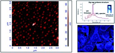
Hexagonal boron nitride (h-BN) has a layered structure similar to graphite and can be synthesized in the forms of nanotubes and nanosheets. These forms of BN have potential applications in mechanical, structural, optoelectronics and semiconductor devices. The formation of quantum dots of BN has expanded new physical properties such as fluorescent behavior. In the present study, hexagonal boron nitride (h-BN) nanoflakes have been synthesized by reaction of B2O3 and (NH2)2CO under a controlled atmosphere. BN nanoflakes, as observed in transmission electron microscopy (TEM) and scanning electron microscopy (SEM), were found to have wide size ranges of 6–35 nm. HRTEM for a single particle was also performed to confirm the formation and interplanar spacing corresponds to h-BN. Fourier transformation infrared spectroscopy (FTIR) spectra indicate strong B–N absorption at 1410 cm−1 and 799 cm−1. Absorption spectra of the product, investigated by UV-Vis spectrophotometry, reveal the characteristic peak of h-BN at 205 nm. Luminescence was recorded by fluorescence spectrophotometry and strong luminescence peaks at 411 nm and 435 nm, both in the blue region of the visible spectra, were found. Fluorescence properties of BN nanoflakes were used for imaging of cancer cells at different concentrations. BNNFs were found to be biocompatible against breast cancer celline MCF-7.


Introduction

Boron nitride nanomaterials have received more attention in recent years due to their excellent properties such as high thermal conductivity, wear resistance, chemical inertness, wide-band gap, bio-inertness and recently reported fluorescent properties. Emergence of fluorescent properties in quantum dots was reported extensively in the recent past.1 In nanomaterials, fluorescent properties are a result of either size effect (less than 10 nm) or functionalization and size effect both.

As far as fluorescent properties are concerned, quantum dots are the most commonly investigated nanomaterials. Discovery of quantum dots by Alexey Ekimov in 1981 was a revolutionary step in the field of applied nanotechnology.2 From that period, researchers have been continuously reporting advancement in this area. Quantum dots have been widely used for bioimaging3 and optoelectronics4 applications. Various types of semiconductor quantum dots such as carbon dots, Au, Ag, CdS, CdSe, CdTe, GaAs and graphene quantum dots with different synthesis routes have been reported till date.3–11 The quantum dots are effective alternative for the conventional imaging agent due to their vast range of wavelength in fluorescence spectra. The emergence of fluorescence in the nanostructured materials depends on their respective particle size. Carbon has been quite interesting material12–16 for research at nanoscale. Different forms of carbon such as graphene, nanotube and carbon dots has attracted researchers from few decades due to their vast applications, such as mechanical, structural, optical, electronics and optoelectronics etc.17 Hexagonal boron nitride (h-BN), having similar crystal structure and mechanical strength as of graphene, has also attracted attention worldwide in recent years. Boron nitride nanosheets (also known as white graphene) and nanotubes have been much explored due to their high mechanical strength for reinforcement of materials.18–20 Hexagonal boron nitride (h-BN) is a wide band gap semiconductor with a fixed band gap of ∼6 eV. Tuning of band gap of h-BN was also reported by S. Kumari et al. by covalent grafting of imidazolium ionic liquid.21

Very few reports are available on fluorescent nanoflakes as compared to quantum dots. Chromium (Cr3+) doped β-tricalcium phosphate nanoflakes synthesized by microwave assisted wet precipitation are reported to be fluorescent. For this material, increase in doping concentration of Cr3+ resulted in increase of intensity of fluorescence of the nanoflakes. This material was reported as a potential candidate for biomedical fluorescent probe.22 Similarly, Y2O3:Yb3+,Er3+ nanoflakes, synthesized by hydrothermal method, have strong visible luminescence which depends on the OH adsorbed on the surface.23 Strong fluorescent behavior was also reported in graphite-like carbon nitride nanoflakes prepared by heating dicyandiamide at 550 °C in nitrogen and air, successively, for 4 h. Fluorescence in bulk and nanoflakes was measured and only nanoflakes were found to be fluorescent.24 Eu3+-Doped La2O2S nanophosphors with controlled morphology from nanoflakes to micrometer vesicles were synthesized by refluxing method and was reported to be fluorescent.25 Flake like nanomaterial of NdF3, synthesized through liquid phase synthesis, was reported to show fluorescent behavior, too. NdF3 showed dependence on the concentration of the reactants used in the synthesis, as an increase in fluorine concentration resulted in decrease in the intensity of fluorescence.26

In the present article, we are reporting an easy method to synthesize hexagonal boron nitride nanoflakes (BNNF) and their application in bio-imaging. The synthesis technique followed a previously used production route for obtaining BN micro/nano-powders at industrial scale,27,28 though a new post-synthesis ultrasonication step was introduced in our approach to produce BNNFs. This step was introduced to get more yield of lesser size nanoflakes (<20 nm) which were giving rise to fluorescence properties. Very few experimental reports found on fluorescent boron nitride quantum dots were by Lin et al.29 and Li et al.30 Lin et al. have synthesized BNQDs by exfoliating h-BN powder using potassium ions (K+), in order to get monolayered h-BN quantum dots. A method was recently reported for synthesis of boron nitride nanosheets using solid thermal waves.31 In the present research; the process involves application of urea and boron trioxide as precursors to produce fluorescent BN nanoflakes. The method was previously reported to get boron nitride nanoparticles.27 This method does not need application of any special equipment or chemical, number of process steps is less and the process is easily scalable. By this method, we were able to produce BNNFs with sizes in the range of ∼5–35 nm. Boron nitride nanoparticles produced by the reported method27,28 was not having fluorescence property which suggests that emergence of fluorescence can be observed in smaller size structures only. The as-synthesized BNNFs were applied for bio imaging of breast cancer epithelial cell line MCF-7; were also found to be showing no significant toxicity.

Experimental

Materials

Boron oxide (B2O3) was purchased from UNI-CHEM, Serbia, urea (NH2CONH2) and ethanol were purchased from SDFCL India Ltd. All the chemical were of analytical reagent (AR) grade and used without further purification. Deionized water was used in all the experiments.

Synthesis

In the synthesis process, 1[thin space (1/6-em)]:[thin space (1/6-em)]1 molar ratio of boron oxide and urea was used. In a glass beaker, 6.962 g of boron oxide (B2O3) was dissolved in 50 ml of deionized water. In this solution 6.006 g of urea (CO(NH2)2) was dissolved and the solution was constantly stirred for 30 minutes in order to make it a homogeneous solution. The prepared solution was poured into an alumina boat and was kept for drying overnight in an oven at 100 °C. The dried mixture, kept in the same alumina boat and completely covered with another alumina boat, was then kept in a tube furnace, heated at a rapid heating rate of 80 °C min−1 to 1050 °C and held for 6 hours. The material was put under a flowing argon gas blanket inside the furnace, to give a non reactive atmosphere resisting unwanted reactions. At 1050 °C, boric oxide (B2O3) reacts with urea (NH2CONH2) to form hexagonal boron nitride (h-BN).26
 
B2O3 + NH2CONH2 → 2BN + 2H2O + CO2 (1)

Most of the h-BN nanoflakes (BNNFs) were left stuck on the walls of boat as porous alumina boat provides the surface for growth of nanosized morphology. In order to collect boron nitride from the alumina boat, deionized water was added to it, kept for 24 hours at 50 °C and then sonicated in a bath sonicator for an hour. Dispersion was then dried in an oven at 50 °C overnight in order to get dried pure fluorescent h-BN nanoflakes. The as-prepared h-BN was dispersed in deionized water, using probe sonicator with power of 500 W and frequency 20 kHz for 1.5 hour, to get better dispersion and to characterize its fluorescence behavior.

Characterization

Morphological studies were performed under field emission scanning electron microscope (FESEM) (model: Carl Zeiss Ultra Plus) and atomic force microscope (AFM) (model: NT-MDT-INTEGRA). Shape and size of the particles and selected area electron diffraction (SAED) were characterized by transmission electron microscope (TEM) (model: FEI TECHNAI G2) by using drop of suspended sample on the non shining side of carbon coated copper grid. The fluorescence study were performed using fluorescence spectrophotometer (model: Hitachi F-4600, Japan) and absorption study were performed by UV-Vis double beam spectrophotometer (model: Lasany LI-2800). Fourier transform infrared spectroscopy (FTIR) was carried out in FTIR spectrophotometer (model: Thermo Nicolet) using KBr pellets, in wave number range of 4000–400 cm−1. Cell imaging was performed in confocal microscope (Zeiss LSM 780 confocal microscope).

Cell culture

Human mammary adenocarcinoma epithelial cell line, MCF-7 cell, was obtained from National Center for Cell Science (NCCS), Pune, India. All cell culture reagents were from GIBCO (Invitrogen, USA). The MCF-7 cells were maintained in Dulbecco's modified Eagle's media (DMEM) supplemented with 10% fetal bovine serum (heat inactivated) (both from Invitrogen, Carlsbad, CA, USA) and 1% antibiotic (100 U ml−1 of penicillin and 100 μg ml−1 streptomycin) (Himedia, Mumbai, India) mixed at 37 °C in humidified atmosphere in a CO2 incubator.

BNNFs cellular uptake

For this experiment the MCF-7 cells were grown in a 6-well plate to a density of 0.5 × 10⁶ cells per well, and then incubated with various concentrations of BNNF (1–20 μg ml−1) at 37 °C for 24 h. Afterwards, the cells were washed 3 times with PBS and then viewed directly under fluorescence microscope (Zeiss, Axiovert 25, Germany).

MTT assay

The cytotoxicity of the test material was determined by estimating the mitochondrial activity of treated cells where the live cells transform the yellow coloured MTT solution to insoluble purple formazan product. For this assay the cells were cultured in 96 well tissue culture plate with a cell density of 104 per well. After the attachment, the cells were incubated for 24 hours and 48 hours in a culture medium containing different doses of BNNFs. On completion of the incubation, the medium from each well was withdrawn. Subsequently the cells were washed with phosphate-buffered solution (PBS). Then 10 μl solution of MTT of concentration 5 mg ml−1 was added to each wells of the plate incubated for 4 h. Eventually, the medium was withdrawn from each well a and 200 μl of DMSO was added to dissolve formazan crystals. A multi-mode microplate reader (BMG FLUOstar OPTIMA Microplate Reader) was used to record the absorbance of each well at single wavelength of 570 nm. For calculating the relative percentage of cell viability [mean (%) ± SEM, n = 3], the following equation was used where untreated cells were used as control:
% cell viability = [absorbance at 570 nm (treated sample)/absorbance at 570 nm (in control) sample] × 100%

Statistical analysis

The experiments were performed in triplicates and the results were expressed as mean ± standard deviation. The statistical significance was evaluated by one-way ANOVA at p < 0.05 level of significance. The statistical packages used were Origin 6.1 software (Origin Lab Corporation, USA) and GraphPad Prism 5.04 (GraphPad Software, San Diego, CA).

Results and discussion

Two modifications were adopted in the process proposed by Rudolph et al. for synthesizing h-BN by urea route.27 Firstly, equal molar ratio of urea and boron oxide was used according to the reaction (reaction (1)), to get high yield of nanoflakes and to reduce the unreacted product formation, which would have otherwise remained as impurity in the product. Secondly, the extraction of h-BN from alumina boat by ultrasonicating it at a power of 500 W and 20 Hz frequency with energy of 9.9 GJ for 1.5 h to extract smaller size nanoflakes from the porous surface of alumina boat. This will increase the yield of smaller size nanoflakes. High energy ultrasonication also ensures formation of finer and thinner nanoflakes. Prepared BN nanoflakes were dispersed well in deionized water and this dispersion was further used for various analysis including AFM, FESEM, and TEM. However, the as-synthesized BNNFs were observed as agglomerates (ESI Fig. S1) only. After long ultrasonication treatment finally achieved better dispersion of BNNFs. The resulting dispersion was investigated in FE-SEM and TEM to confirm morphology and structure.

Structure and morphology of BNNFs

Low and high magnification TEM images are presented in Fig. 1(a) and its inset showing distribution of different sizes of BN nanoflakes. Bigger nanoflakes were found to have disc type morphology. Average size of the flakes was measured to be around ∼16 nm with the range of ∼5–35 nm. SAED pattern (Fig. 1(b)) confirms the final product to be h-BN. The planes observed from SAED pattern were (002), (100) and (110) and matched well with h-BN crystal structure. X-Ray diffraction pattern (ESI Fig. S2) was also recorded for BNNFs and found closely matched with h-BN with JCPDS reference no. 85-1068 and strongly supports observations of SAED pattern. The HR-TEM images of BNNFs shown in Fig. 1(c) consists of one single nanoflakes with mean spacing between the adjacent planes being 0.215 nm, which is indicative of lattice spacing of plane (100) of hexagonal lattice.29 The measurement for spacing of adjacent layers was performed by using IFFT images (inset) generated by using FFT images of HR-TEM image using software Gatan Digital Micrograph to clear the lattice fringes in the images. Fig. 1(d) presents the statistical distribution of sizes of the nanoflakes in the product. The size distribution by volume was also performed by Zetasizer Nano ZS90 and was found to be distributed over a range of 20–40 nm (ESI Fig. S3).
image file: c6ra05288f-f1.tif
Fig. 1 (a) Low magnification TEM images with high magnification image in inset, (b) SAED pattern of BN nanoflakes (all planes corresponds to h-BN structure), (c) HRTEM image of the as prepared boron nitride nanoflakes and its IFFT simulated image (inset) from the selected section and (d) size distribution of BNNFs, as measured from multiple TEM images. (e) FESEM image of the sample; smaller sized BNNFs spread throughout the substrate.

Another important feature to be observed from the low magnification TEM image is the agglomeration of flakes, in spite of having long ultrasonication of the sample. This indicates high interaction between BN nanoflakes. FESEM (Fig. 1(e)) was performed on this sample to understand the morphology in a much better way. Before placing the sample in FESEM, it was well sonicated to get a thin and stable dispersion; a drop of this dispersion was then put on the ultrasonicated cleaned silicon wafer and dried. FESEM images also clearly show the size distribution of nanoflakes.

Atomic force microscopy (AFM) was performed on the BNNFs, in order to measure thickness of the nanoflakes (Fig. 2). Samples were well dispersed in water and a single drop was placed on ultrasonically cleaned silicon wafer by drop casting method, followed by drying in oven. Thickness was measured to be around 14 ± 6.7 nm. Moreover, BNNFs were found to be flat and irregular in shape.


image file: c6ra05288f-f2.tif
Fig. 2 AFM images of BN nanoflakes and their thickness variations.

Mechanism of formation of BNNFs

In order to explain the size variation of BNNFs, it is important to understand the underlying mechanism of BNNF synthesis. During synthesis, B2O3 forms complex with urea32 during rapid heating, which is stable enough and does not degrade till 600 °C. This turns into h-BN in argon atmosphere beyond 1000 °C (as per the reaction in eqn (1)). Once the free molecules of boron nitride in solid solution supersaturate, they have tendency to condense either on the surface of larger particles or inside porous surface of alumina boat. Therefore to minimize overall surface energy, smaller sized flakes shrinks and larger sized flakes further grow, leading to wide size variation in BN nanoflakes.

Optical and luminescence properties of BNNFs

UV-Vis absorption spectrum (Fig. 3(a)) shows absorption peak at 205 nm, which is a characteristic peak for h-BN and a small hump at 243 nm which is believed to be due to presence of vacancy defects in the crystal structure of nanoflakes. Such defects are reported to contribute in luminescence in boron nitrogen system.33 FTIR spectrum of the sample (Fig. 3(b)) shows presence of B–N in the sample. While the peak at 1410 cm−1 is for B–N and that at 799 cm−1 for B–N–B vibrations, sharp peak at 508 cm−1 presents bending vibration of O–B–O. The bands observed in BN (1410 cm−1 and 799 cm−1) and boron oxynitride (in 1100–900 cm−1 N–B–O stretching region) vibrations clearly indicate the transfer from BO2− to BO species.33
image file: c6ra05288f-f3.tif
Fig. 3 (a): UV-Vis spectra of the BN sample, showing absorption peak at 205 nm and hump at 243 nm. (b) FTIR spectrum of the product confirming BN linkage and formation of BN by strong absorption at 1410 cm−1.

An excitation wavelength of 205 nm was given to BNNFs sample dispersed in water and the emission response was recorded in the range of 215 nm to 800 nm. Strong emission peak at 415 nm (Fig. 4) is believed to be originated from zig-zag carbene structures induced fluorescence behavior in graphene like system, which was reported previously,29,33 creating quantum confinement. The hump at 435 nm emerges due to impurity presence in sample. This might be due to trace amount of BO2 as impurity, which was also supported by FTIR spectra, in which O–B–O bending vibrations at 508 cm−1 is present. In spite of being an impurity in the BNNF structure, BO2 species can emit a single peak blue emission.32


image file: c6ra05288f-f4.tif
Fig. 4 Fluorescence spectra of BNNF sample at an excitation of 205 nm using water as solvent and in inset, picture of luminescence under UV light.

The emission due to zigzag carbene structure creates quantum confinement in nanoflakes that strongly contribute by emitting blue wavelength as major peak (415 nm) in the fluorescence spectra. Presence of zigzag edges with carbene like triplet ground state corresponding to transition from highest occupied molecular orbit (HOMO) to σ and π orbitals of lowest occupied molecular orbit (LUMO) is similar to the case of graphene quantum dots (GQDs) reported by L. Lin et al.34 TEM images (Fig. 1(a) and inset) of nanoflakes show non-uniform edges creating zigzag like structures which strongly contribute to the fluorescence behavior. The closed shell species BO2 has a linear ground state (1Σg+)1 which is fundamentally indicated by a degenerated πg orbital. In this system, the first excitation state is 2Πg, so the transition between 1Σg+ to 2Πg radiates blue emission. Corresponding energy level for wavelength 415 nm is ∼2.99 eV and for 435 nm ∼2.9 eV. The energy levels were found to be very close to the reported experimental findings.29 The proposed luminescence diagram is shown in Fig. 5. Here it is important to mention that size of the nanostructures also plays direct or indirect role in emergence of fluorescence. It may be concluded here that fluorescence emergence is a synergistic effect of groups present on edges as well as size of the nanostructure. Quantum yield of the sample was also calculated using standard reference quinine sulphate. The experiment detail and the parameters was given in the ESI (Table S1). The quantum yield was found to be 2.5% for BNNFs.


image file: c6ra05288f-f5.tif
Fig. 5 Luminescence diagram of as prepared boron nitride nanoflakes.

In order to investigate the effect of excitation wavelength on fluorescence behavior of BNNFs, fluorescence spectra was further recorded at excitation of 243 nm. No significant change in the fluorescence spectra (ESI Fig. S4(a)) was detected. Therefore, it may be concluded that the fluorescence spectra of synthesized material has either no significant effect of excitation on it or the emission is broad for a range of different excitation hence the contribution may be overlapping with the existing. It can further be understood from this observation that defects present on BNNFs are having either no significant effect on fluorescence spectra or it is overlapping with dominating emission, due to presence of functional groups and zigzag carbene structure of h-BN. To study further the effect of oxidation, BNNFs were heat treated at 1000 °C for 2 h in presence of air. This oxidation was also not having any significant effect on the major peak in the fluorescence spectra (ESI Fig. S4(b)). The effect on the peak due to BO2− species was more significant, the major peak (at 415 nm) was significantly overlapped with the peak due to BO2− species (at 435 nm) as a result the peak became broader, this indicate that the fluorescence due to BO2− species has increased i.e. population of BO2− functional group on the surface of nanoflakes has been increased upon sintering in presence of air. BNNFs were also sintered in a reduced atmosphere, in presence of Ar–H2 (Ar-90% + H2-10%) mixture. The product was re-dispersed in water to record fluorescence spectra; the spectra could not be able to produce any emission in UV or visible range. This is evident that functional group present as suggested by FTIR spectra are strongly responsible for fluorescence spectra as most of the functional group would have been reduced by the sintering in reduced atmosphere. Similar observation on the fluorescence behavior of boron nitride quantum dots was reported earlier (L. Lin et al.)29 and was correlated to the presence of BO2−. In case of graphene quantum dots (GQD) also, fluorescence was found to be a result of various functional group (C–OH, C[double bond, length as m-dash]O and –O–C[double bond, length as m-dash]O) present on GQDs, resulting from partial oxidation.3

Biolabeling of cells by BNNFs

Strong blue fluorescence of as-synthesized BNNFs was found to be a promising feature for bio-imaging of cells. Confocal microscopy images of MCF-7 cells treated with various concentrations of BNNFs are shown in Fig. 6. It is clearly visible that concentration of 1 μg ml−1 of fluorescent BNNFs is not quite effective for attaching and imaging of MCF-7 cells. On the other hand, 10 μg ml−1 and 20 μg ml−1 concentrations of BNNFs are found to be suitable for labeling the cancer cells and their imaging, as observed from images acquired via confocal microscope (Zeiss LSM 780 confocal microscope) (Fig. 6). Another important feature has been observed from the images is the absence of any morphological change of the cells upon addition of fluorescent BNNFs on cancer cells, even after 24 hours of incubation. This fact demonstrates that as-prepared fluorescent BNNFs do not have any cytotoxicity effect on the test cancer cells. It is known that most of quantum dots like CdS, CdSe, CdTe, PbSe, PbS, InAs and InP etc. are toxic35,36 to the cells. Thus BN could be a potential alternate candidate due to their inert nature.1 To investigate cytotoxicity against cancer cells MTT assay was performed and found no significant toxic behavior. These observations help to conclude that as-synthesized fluorescent BNNFs can be applied to image cancer cells, without showing any toxic behavior. This non-toxic activity is critical since during its application for imaging, the fluorescent BNNFs may leach into both cancerous as well some non cancerous cells. At least our preliminary studies showed that like cancerous cells, BNNFs are also non-toxic to normal cells. However, further studies are needed to establish that nanoflakes are going inside or attaching on the surface of cells.
image file: c6ra05288f-f6.tif
Fig. 6 Confocal microscopy images of MCF-7 cells treated with various concentrations of BNNFs for 24 h. Scale bar represents 50 μm.

Biocompatibility

Cytotoxicity of a bio-imaging agent can be major drawback for its practical application. In order to understand the cytotoxicity effects of BNNFs, MTT assay was performed. The results, presented in Fig. 7, clearly depicts that about 97% and 94% of MCF-7 cells were viable in presence of 10 μg ml−1 of BNNFs, till 24 h and 48 h incubation periods, respectively. As BNNFs concentration was increased to 60 μg ml−1, cell viability eventually decreased to 80% after 48 h incubation, while after 24 h of incubation the cell viability decreased marginally by 1% (p < 0.05). The error bars indicated in the graph represent the standard deviation calculated from the triplicate test values. These results thus illustrate very low toxicity effects of BNNFs, and appear to be optimal for bioimaging applications. It is important here to note that previous studies have also shown that boron nitride quantum dots (BNQDs) are biocompatible in nature and can be applicable to bioimaging of cells.29
image file: c6ra05288f-f7.tif
Fig. 7 MTT based cytotoxicity assay of fluorescent BNNFs against MCF-7 cells. The percentage cell viability is assumed to be 100% for control in each case.

Conclusion

A simple, easy-to-scale-up and cost-effective synthesis technique was followed for synthesizing BNNFs. Structural characterizations showed the product to have distinctly different particles sizes, in the range of 5–35 nm and elliptical disc type morphology. TEM characterization of the sample confirmed h-BN to be the major phase in the product. The fluorescence emission of the sample was in the range of blue emission. The cytotoxicity of fluorescent BNNFs was found to be insignificant for the concentrations used. Therefore, based on the current findings it could be speculated that the fluorescent BNNFs can be successfully applied in bio labeling of cancer cells after further validation using in vivo models.

Acknowledgements

Authors are thankful to Institute Instrument Centre and Centre of Excellence: Nanotechnology, IIT Roorkee, for allowing access to various characterization facilities.

References

  1. D. Golberg, Y. Bando, Y. Huang, T. Terao, M. Mitome, C. Tang and C. Zhi, ACS Nano, 2010, 4, 2979–2993 CrossRef CAS PubMed.
  2. A. L. Ekimov and A. A. Onuschenko, JETP Lett., 1981, 34, 345 Search PubMed.
  3. Y. Song, S. Zhu and B. Yang, RSC Adv., 2014, 4, 27184–27200 RSC.
  4. Z. Zhang, J. Zhang, N. Chen and L. Qu, Energy Environ. Sci., 2012, 5, 8869–8890 CAS.
  5. X. Yang, Y. Zhuo, S. Zhu, Y. Luo, Y. Feng and Y. Dou, Biosens. Bioelectron., 2014, 60, 292–298 CrossRef CAS PubMed.
  6. Z. Li, R. Sun, Y. Ni and S. Kokot, Anal. Methods, 2014, 6, 7420–7425 RSC.
  7. P. G. Luo, F. Yang, S. T. Yang, S. K. Sonkar, L. Yang, J. J. Broglie, Y. Liua and Y. P. Sun, RSC Adv., 2014, 4, 10791–10807 RSC.
  8. R. Wang and F. Zhang, J. Mater. Chem. B, 2014, 2, 2422–2443 RSC.
  9. A. Sachdev, I. Matai and P. Gopinath, RSC Adv., 2014, 4, 20915–20921 RSC.
  10. G. E. LeCroy, S. K. Sonkar, F. Yang, L. M. Veca, P. W. K. N. Tackett, J. J. Yu, E. Vasile, H. Qian, Y. Liu, P. G. Luo and Y. P. Sun, ACS Nano, 2014, 8, 4522–4529 CrossRef CAS PubMed.
  11. S. J. Soenen, B. B. Manshian, T. Aubert, U. Himmelreich, J. Demeester, S. C. D. Smedt, Z. Hens and K. Braeckmans, Chem. Res. Toxicol., 2014, 27, 1050–1059 CrossRef CAS PubMed.
  12. P. Simon and Y. Gogotsi, Nat. Mater., 2008, 7, 845–854 CrossRef CAS PubMed.
  13. S. Zhang, Nat. Biotechnol., 2003, 21, 1171–1178 CrossRef CAS PubMed.
  14. S. Guo and S. Dong, Chem. Soc. Rev., 2011, 40, 2644–2672 RSC.
  15. J. Wang, Electroanalysis, 2005, 17, 7–14 CrossRef CAS.
  16. A. Bianco, K. Kostarelos and M. Prato, Curr. Opin. Chem. Biol., 2005, 9, 674–679 CrossRef CAS PubMed.
  17. W. Choi, I. Lahiri, R. Seelaboyina and Y. S. Kang, Crit. Rev. Solid State Mater. Sci., 2010, 35, 52–71 CrossRef CAS.
  18. D. Lahiri, A. Hadjikhani, C. Zhang, T. Xing, L. H. Li, Y. Chen and A. Agarwal, Mater. Sci. Eng., A, 2013, 574, 149–156 CrossRef CAS.
  19. D. Lahiri, V. Singh, A. P. Benaduce, S. Seal, L. Kos and A. Agarwal, J. Mech. Behav. Biomed. Mater., 2011, 4, 44–56 CrossRef CAS PubMed.
  20. B. Mortazavi and G. Cuniberti, RSC Adv., 2014, 4, 19137–19143 RSC.
  21. S. Kumari, R. Gusain and O. P. Khatri, RSC Adv., 2016, 6, 21119–21126 RSC.
  22. A. Z. Alshemarya, Y. F. Goha, I. Shakirb and R. Hussain, Ceram. Int., 2015, 41, 1663–1669 CrossRef.
  23. G. De, W. Qin, J. Zhang, J. Zhang, Y. Wang, C. Cao and Y. Cui, Solid State Commun., 2006, 137, 483–487 CrossRef CAS.
  24. L. Chen, D. Huang, S. Ren, T. Dong, Y. Chi and G. Chen, Nanoscale, 2013, 5, 225–230 RSC.
  25. D. Ma, S. Liu, Y. Zhang, C. Zhang and S. Huang, J. Exp. Nanosci., 2013, 8, 434–441 CrossRef CAS.
  26. L. Tian, P. Lian, Q. Sun, P. Long, S. Xiang and G. Zhu, Mater. Res. Bull., 2013, 48, 48–51 CrossRef CAS.
  27. S. Rudolph, Am. Ceram. Soc. Bull., 2000, 79, 50 CAS.
  28. K. Raidongia, A. Gomathi and C. N. R. Rao, Isr. J. Chem., 2010, 50, 399–404 CrossRef CAS.
  29. L. Lin, Y. Xu, S. Zhang, I. M. Ross, A. C. M. Ong and D. A. Allwood, Small, 2014, 10, 60–65 CrossRef CAS PubMed.
  30. H. Li, R. Y. Tay, S. H. Tsang, X. Zhen and E. H. T. Teo, Small, 2015, 11, 6491–6499 CrossRef CAS PubMed.
  31. H. H. Nersisyan, T. H. Lee, K. H. Lee, Y. S. An, J. S. Lee and J. H. Lee, RSC Adv., 2015, 5, 8579–8584 RSC.
  32. V. I. Kostikov, M. F. Makhova, V. P. Serjeev and V. I. Treflov, Fiber Science and Technology, ed. V. I. Kostikov, Chapman and Hall, London, 1995, ch. 6, p. 569 Search PubMed.
  33. C. Tang, Y. Bando, C. Zhi and D. Golberg, Chem. Commun., 2007, 44, 4599–4601 RSC.
  34. L. Lin and S. Zhang, Chem. Commun., 2012, 48, 10177–10179 RSC.
  35. Y. Su, Y. He, H. Lu, L. Sai, Q. Li and W. Li, Biomaterials, 2009, 30, 19–25 CrossRef CAS PubMed.
  36. R. Hardman, Environ. Health Perspect., 2006, 114, 165–172 CrossRef PubMed.

Footnote

Electronic supplementary information (ESI) available. See DOI: 10.1039/c6ra05288f

This journal is © The Royal Society of Chemistry 2016