
Synthesis of flexible and up-converting luminescent NaYF4:Yb,Er-PET composite film for constructing 980-nm laser-driven biopower
Zhaojie Wang†
a,
Wei Li†a,
Nuo Yua,
Zixiao Liua,
Lisha Zhangb and
Zhigang Chen *a
*a
aState Key Laboratory for Modification of Chemical Fibers and Polymer Materials, College of Materials Science and Engineering, Donghua University, Shanghai 201620, China. E-mail: zgchen@dhu.edu.cn
bCollege of Environmental Science and Engineering, Donghua University, Shanghai 201620, China
First published on 13th April 2016
Abstract
One of the prerequisites for the development of wireless nanobiodevices (such as nanorobots) is to utilise an in vivo energy source as a biopower component that is continuously available in the operational biological environment. To address this problem, herein we have developed a new model of a 980-nm laser driven photovoltaic cell (hereafter abbreviated as 980LD-PC) by incorporating a flexible up-converting luminescent film and flexible amorphous silicon thin film photovoltaic cell. NaYF4:Yb,Er-PET composite films are prepared by using film casting technology, and they exhibit excellent up-converting luminescence, flexibility and transparency. Subsequently, the composite film with NaYF4:Yb,Er/PET weight ratio of 20% is adhered on the surface of a flexible amorphous silicon film solar cell for constructing a flexible 980LD-PC photovoltaic cell. Under the irradiation of a 980-nm laser (intensity: 720 mW cm−2, area: 0.25 cm2) that is slightly lower than the conservative limit (726 mW cm−2) for human skin exposure, the resulting 980LD-PC exhibits strong up-converting luminescence, and it has a maximal electrical output of 94 μW. More importantly, after being covered with a layer of chicken skin (thickness: ca. 1 mm) as a model of biological tissue, 980LD-PC still exhibits bright up-converting luminescence and a maximal electrical output of 62 μW which is high enough to drive biological devices including in vivo nanorobots (power: at least 1 μW) and cardiac pacemakers (power: about 10 μW). This research paves the way for the development of novel flexible biopower sources to drive wireless nanobiodevices and other biodevices implanted under the human skin.
1. Introduction
Nanobiodevices have been currently attracting widespread scientific and technological interest due to their small size and tuned performance.1–9 Among them, wireless self-powered nanodevices (such as nanorobots1,2) have great potential for real-time diagnosis and therapeutic intervention, such as in cancer treatment, and tissue and organ repair. For designing and constructing these wireless nanodevices, one of the prerequisites is to obtain an in vivo energy source as a biopower component that is continuously available in the operational biological environment. Thus, the design and construction of in vivo biopower devices with superior performances have been a primary research objective.The most natural biopower is via nanomotors that have great potential to drive wireless nanodevices to move in vivo. Currently, several nanomotors have been well developed in the field of drug-delivery, precision nanosurgery, biosensing, and environmental sustainability.10–14 For example, a self-propelled nanomotor with tuned motion speed has been constructed based on a Pt-catalyzed decomposition reaction of H2O2, and it exhibits excellent drug-delivery behavior in a biological environment.12 Additionally, a magnetically driven (fuel-free) nanomotor has been demonstrated to be useful for the pick-up and transport of various drug carriers through a predefined route under an external magnetic field.13 However, by using nanomotors as the only biopower component, it will be difficult to efficiently monitor and control in vivo wireless nanodevices, which will probably limit the applications of the nanodevices.
In fact, for the efficient operation (such as monitoring, driving and communication) of these wireless nanobiodevices, the most effective biopower should be an in vivo electrical source.15,16 There are chiefly three kinds of biological electrical sources that have great potential as biopower, including nanogenerators driven by mechanical sources (ultrasonic waves,17,18 triboelectrification,19 random mechanical actions,20 and muscle-movement21), biofuel cells22–25 driven by chemical energy, and biological photovoltaic cells15,16,26 driven by a 980-nm laser. Among these biological electrical sources, 980-nm laser driven photovoltaic cells (hereafter abbreviated as 980LD-PCs) have attracted much interest due to their high electrical output (>20 μW)15,16,26 compared with that from nanogenerators (driven by muscle-movement)21 and biofuel cells.25 In 2009, our group reported the first design model and preparation of 980LD-PC by inserting a Na(Y1.5Na0.5)F6:Yb,Er nanorod film in a conventional dye sensitized solar cell (DSSC) with liquid electrolyte and FTO glass. When 980LD-PC was irradiated by a 980-nm laser with a power of 1 W, the Na(Y1.5Na0.5)F6:Yb,Er nanorod film component emitted visible up-converting luminescence which led to the DSSC component to produce electricity (∼470 μW).15 To improve the conversion efficiency and avoid possible leaking of the liquid electrolyte, we further improved 980LD-PC by inserting the efficient NaYF4:Yb,Er film in DSSC with gel electrolyte,16 and it had a maximum output power of 44.5 mW under the irradiation of a 980-nm laser with a safe intensity of 720 mW cm−2. Another kind of 980LD-PC based on organic P3HT-PCBM solar cell was also developed, and it exhibited a maximal output power of 2.61 μW under the irradiation of a 980-nm laser with a power of 21.63 mW.26 Under the irradiation of 980-nm lasers, all these 980LD-PCs, even when covered by biological tissues still worked well, and their electrical output powers were efficient enough to drive many kinds of biodevices such as in vivo nanorobots (power: at least 1 μW) and cardiac pacemakers (power: about 10 μW).15,16,26
It should be pointed out that although our 980LD-PCs have been successfully demonstrated based on DSSC,15,16 the use of rigid FTO glass will greatly limit the miniaturization of 980LD-PC, resulting in difficulties for the construction and biological applications of wireless self-powered nanodevices. Undoubtedly, it would be better to replace the FTO glass substrate with a flexible plastic substrate. However, 980LD-PCs based on DSSC would have very poor electrical output if constructed on plastic substrates, since traditional DSSCs on plastic substrates usually exhibit much poorer photoelectrical conversion efficiency compared those on FTO glass.27,28
To address these problems, in the present work, we designed and developed a new model of 980LD-PCs by incorporating a flexible up-converting luminescent film and a flexible amorphous silicon thin film photovoltaic cell. The flexible up-converting luminescent film was prepared by using film casting technology with a trifluoroacetic acid (TFA)–chloroform mixture solution containing NaYF4:Yb,Er nanorods and polyethylene terephthalate (PET). The optimized NaYF4:Yb,Er-PET composite film (NaYF4:Yb,Er, 20%) was used to coat the flexible amorphous silicon film solar cell for constructing 980LD-PCs. Under the irradiation of a 980-nm laser (intensity: 720 mW cm−2, area: 0.25 cm2), the resulting flexible 980LD-PC, either without or with chicken skin (thickness: ca. 1 mm) covering, exhibited a maximal electrical output of 94 μW and 62 μW, respectively, which are high enough values to drive biological devices including cardiac pacemakers (power: about 10 μW).
2. Experimental
2.1 Preparation of NaYF4:Yb,Er nanorods
All of the chemicals were received from Sinopharm Chemical Reagent Co., Ltd (China). NaYF4:Yb,Er nanophosphors were prepared by a modified hydrothermal/solvothermal method.29,30 In a typical synthesis process, LnCl3 (Ln = 78 mol%Y + 20 mol%Yb + 2 mol%Er, 1 mmol) aqueous solution (2 mL) was added to a mixture solution containing sodium oleate (4 g), water (16 mL), ethanol (30 mL) and oleic acid (20 mL) under magnetic stirring, forming a homogeneous solution. Subsequently, NaF aqueous solution (5 mL, 1.0 M) was dropwise added to the above solution. The resulting solution was stirred for about 10 min, then transferred to a 100 mL autoclave, sealed, and treated at 200 °C for 30 h. The system was cooled to room temperature naturally, and the NaYF4:Yb,Er nanorod precipitate was collected by centrifugation and washed with ethanol several times. Finally, the precipitate was dried under vacuum at 50 °C for 24 h.2.2 Synthesis of flexible NaYF4:Yb,Er-PET composite film
In a typical film synthesis process, 330 mg solid polyethylene terephthalate (PET, injection molding grade) and 8.3 mg NaYF4:Yb,Er nanorods (weight ratio of NaYF4:Yb,Er/PET was 2.5%), were added into the mixture solution of chloroform (2.5 mL) and trifluoroacetic acid (TFA, 0.5 mL), and the mixture was magnetically stirred until a homogeneous dispersion was formed. Then the NaYF4:Yb,Er-PET dispersion was cast on a smooth glass plate, followed by heating at 60 °C for 30 min to remove the solvent. The casting–heating process was repeated several times until a 250 μm thick NaYF4:Yb,Er-PET composite film was prepared. Subsequently, the glass plate was placed in water to peel off the NaYF4:Yb,Er-PET composite film automatically. Finally, the NaYF4:Yb,Er-PET composite film was dried in an oven at 60 °C for 24 h, and was denoted as 2.5%NaYF4:Yb,Er-PET. For comparison, 5.0–20%NaYF4:Yb,Er-PET composite films with different weight ratios (NaYF4:Yb,Er/PET: 5.0–20%) were prepared by increasing the NaYF4:Yb,Er nanorod content.2.3 Construction of 980LD-PC
Flexible amorphous silicon film photovoltaic cells were purchased from Suzhou Flextech Company, and had a structure of polymer/Ag–ZnO/n-i-p a-Si:H/ITO/Al and a photoelectrical conversion efficiency of 10%. Subsequently, NaYF4:Yb,Er-PET composite film was adhered on the surface of ITO layer from the photovoltaic cell with transparent epoxy resin adhesive for the construction of 980LD-PC.2.4 Characterization and photoelectrical measurement
The morphologies of the NaYF4:Yb,Er sample and NaYF4:Yb,Er-PET composite film were investigated by field emission-scanning electron microscopy (FE-SEM, Hitachi S-4800). The X-ray diffraction (XRD) pattern of the NaYF4:Yb,Er sample was recorded on a Bruker D4 X-ray diffractometer using a Cu-Kα radiation source (λ = 1.5418 Å). The Fourier-transform infrared (FTIR) spectrum was measured by an IRPRESTIGE-21 spectrometer (Shimadzu) using KBr pressed pellets. Up-conversion luminescence spectra were measured using a JASCO FP-6600 spectrometer, but the excitation source was an external 0–1 W adjustable 980-nm semiconductor laser device including an optic fiber accessory with a diameter of 800 mm (Beijing Hi-Tech Optoelectronic Co., China) instead of the xenon source in the spectrometer.The photocurrent–voltage curves of 980LD-PC were measured by using a computerized Keithley Model 2400 SourceMeter unit. An adjustable 980-nm semiconductor laser device with an output area of 0.25 mm2 was used as the light source. Fresh skin from a dead chicken was washed with water, fixed on a plastic support and then used as both a model of biological tissue and a barrier layer in the 980-nm laser pathway, which is similar to our previous report.16
3. Results and discussion
3.1 Preparation and characterization of NaYF4:Yb,Er nanorods
NaYF4:Yb,Er sample was synthesized by a typical hydrothermal/solvothermal method in an oleic acid/ethanol/water solvent system at 200 °C for 30 h. The morphology and size of NaYF4:Yb,Er sample were studied by SEM and TEM images (Fig. 1a–c). The NaYF4:Yb,Er sample consists of worm-like nanorods with diameters of about 200 nm and lengths of 0.5–1 μm (Fig. 1a and b). A high-resolution TEM image (Fig. 1c) shows an interplanar spacing of 2.97 Å, which corresponds to the d spacing for the (110) planes of hexagonal NaYF4:Yb,Er. Usually, high temperature and long reaction time favor the formation of NaYF4:Yb,Er nanorods instead of nanoparticles,31 which facilitate the reduction of surface defects and therefore improve the luminescence efficiency.32 In addition, the phase of NaYF4:Yb,Er nanorods was investigated by XRD pattern (Fig. 1b). NaYF4:Yb,Er nanorods have high crystallinity with strong and well-defined diffraction peaks. The main diffraction peaks at 17.2, 30.1, 30.8, 43.5, 53.8° are assigned to (100), (110), (101), (201), (211) planes, respectively, which can be readily indexed as pure-hexagonal phase NaYF4 (JCPDS card 16-0334) (Fig. 1b).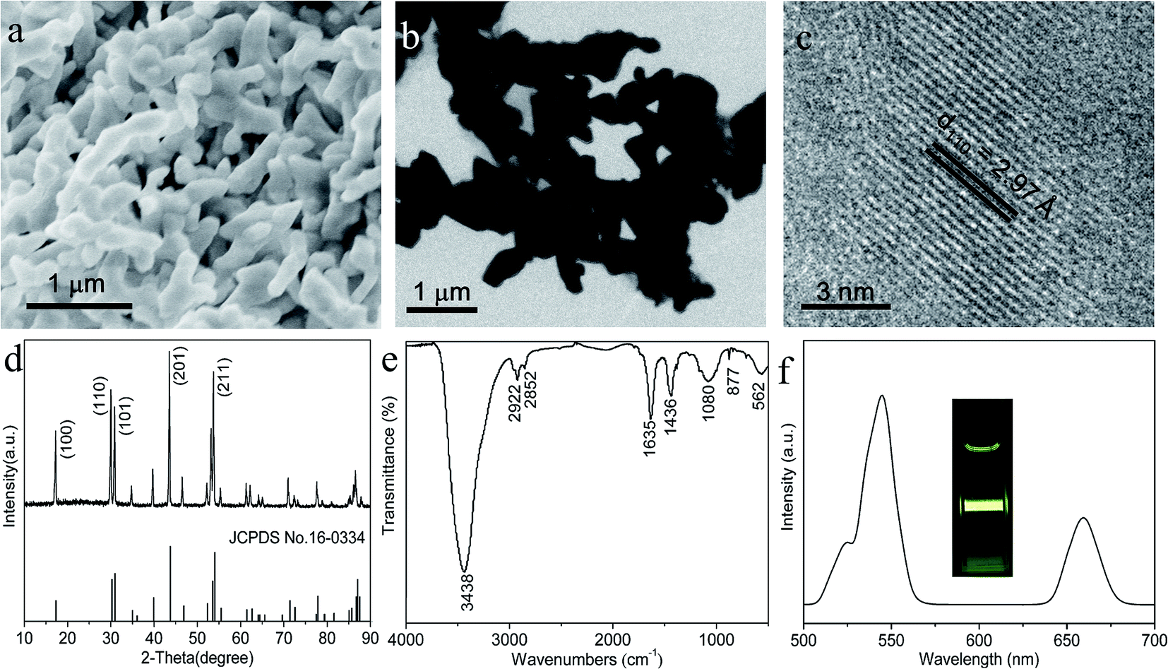 | ||
| Fig. 1 (a) SEM image, (b and c) TEM image, (d) XRD pattern, (e) FT-IR spectrum and (f) up-conversion luminescence spectrum of NaYF4:Yb,Er nanorods. The inset in (f) shows an up-converting luminescence photo of NaYF4:Yb,Er dispersion. | ||
Surface functional chemical groups of NaYF4:Yb,Er nanorods are important for the subsequent film preparation. Thus, the capping ligands on their surface was identified by FT-IR spectroscopy (Fig. 1c). NaYF4:Yb,Er nanorods exhibit a broad band at around 3438 cm−1, due to the O–H stretching vibration from adsorbed water. The bands at 2922 and 2852 cm−1 are assigned to the asymmetric (νas) and symmetric (νs) stretching vibrations of methylene (–CH2–) units, respectively.30 Two bands at 1635 and 1436 cm−1 are related to the asymmetric (νas) and symmetric (νs) stretching vibrations of the carboxylic group, respectively.33 In addition, the band at 1080 cm−1 corresponds to C–O stretching vibration coordinating to metal cations,34 suggesting the formation of chemical bonds between oleic acid ligands and NaYF4:Yb,Er. Based on the above results, one can conclude that there are oleic acid ligands on the surface of NaYF4:Yb,Er nanorods.
As a result of the presence of oleic acid ligands, NaYF4:Yb,Er nanorods can be readily dispersed in some nonpolar organic solvents such as cyclohexane or chloroform. A chloroform dispersion containing NaYF4:Yb,Er nanorods shows very strong green emission under 980-nm laser irradiation (inset of Fig. 1d) and the up-converting luminescent spectrum of the dispersion was recorded (Fig. 1d). The spectrum is similar to what has been reported previously for these materials,15,16,29,30,35 and it exhibits three distinct Er3+ emission bands. A relatively weak red emission is observed between 635 and 680 nm due to the transition from 4F9/2 to 4I15/2. The dominant green emissions between 514 and 534 nm and between 534 and 560 nm are attributed to the 2H11/2 → 4I15/2 and 4S3/2 → 4I15/2 transitions, respectively. Strong green emissions will facilitate the enhancement of the photoelectrical conversion of 980LD-PC.15,16
3.2 Synthesis and characterization of NaYF4:Yb,Er-PET composite films
Subsequently, NaYF4:Yb,Er-PET composite films were prepared by the casting–heating process with a TFA-chloroform mixture solution containing NaYF4:Yb,Er nanorods and PET (Fig. 2a). Composite films with different NaYF4:Yb,Er content could be obtained by simply changing the weight ratio of NaYF4:Yb,Er/PET (2.5, 5.0, 7.5, 10.0, 12.5, 15.0, 17.5 and 20.0%). All composite films are free standing and can be easily curved due to their high flexibility, as shown in typical photos (Fig. 2b and c) of 20%NaYF4:Yb,Er-PET composite films. Since 20%NaYF4:Yb,Er-PET composite film has the highest NaYF4:Yb,Er content, it was used as the model for further morphology characterization. Fig. 3 shows the typical surface and cross-section morphologies of the 20%NaYF4:Yb,Er-PET composite film. Obviously, the film surface is uniform and smooth, and no cracks are observed (Fig. 3a). Furthermore, it is clear that NaYF4:Yb,Er nanorods are embedded in the PET film with good dispersibility. The cross-sectional SEM image (Fig. 3b) reveals that the 20%NaYF4:Yb,Er-PET composite film has a typical thickness of ∼250 μm. In the middle of film, a cross-sectional SEM image with high magnification further confirms that there are many NaYF4:Yb,Er nanorods embedded in the PET film (inset of Fig. 3b), which is consistent with the surface morphology (Fig. 3a). | ||
| Fig. 2 (a) Schematic illustration of the preparation process of NaYF4:Yb,Er-PET composite films. (b and c) Photos of a typical 20%NaYF4:Yb,Er-PET composite film. | ||
 | ||
| Fig. 3 Typical surface (a) and cross-section (b) morphologies of 20%NaYF4:Yb,Er-PET composite film. | ||
The effects of NaYF4:Yb,Er/PET weight ratio on the up-converting luminescent intensity of NaYF4:Yb,Er-PET composite films were investigated under the irradiation of a 980-nm laser (intensity 720 mW cm−2, area 0.25 cm2). All films exhibit strong up-converting luminescence under the irradiation of a 980-nm laser. With an increase of NaYF4:Yb,Er content from 2.5 to 20%, the intensity of the up-converting luminescence goes up remarkably, as vividly shown in the photos (Fig. 4a). The corresponding up-conversion luminescence spectra of these NaYF4:Yb,Er-PET composite films were also recorded (Fig. 4b). All films have three distinct Er3+ emission bands, including a relatively weak red emission (635–680-nm) and two dominant green emissions (514–534 nm, 534–560 nm). These spectra are very similar to that (Fig. 1d) of a chloroform dispersion containing NaYF4:Yb,Er nanorods, indicating the fact that the embedding process for NaYF4:Yb,Er nanorods has no obvious adverse effects on their up-converting luminescence. In particular, the intensity of up-converting luminescence at 545 nm increases almost linearly with the increase of NaYF4:Yb,Er content (inset of Fig. 4b), indicating the good transparency and inertness of PET as well as the high stability of NaYF4:Yb,Er. When the NaYF4:Yb,Er content reaches 20%, the 20%NaYF4:Yb,Er-PET composite film exhibits the highest up-converting luminescence intensity. With a further increase (>20%) of NaYF4:Yb,Er content, the resulting NaYF4:Yb,Er-PET composite film has higher up-converting luminescence, but we find that the film becomes brittle with poor flexibility and transparency, resulting in problems for the further construction of 980LD-PC.
 | ||
| Fig. 4 Up-converting luminescence images (a) and the corresponding up-conversion luminescence spectra (b) of NaYF4:Yb,Er-PET composite films with different weight ratio (NaYF4:Yb,Er/PET: 2.5, 5.0, 7.5, 10.0, 12.5, 15.0, 17.5 and 20.0%). The inset in (b) shows the approximate linear relationship between the luminescence intensity at 545 nm and the weight ratio of NaYF4:Yb,Er/PET. | ||
3.3 Construction and photoelectrical measurement of 980LD-PC
Our previous models concerning 980LD-PCs have been developed based on dye sensitized solar cell (DSSC) containing liquid/gel electrolyte on FTO glass substrates.15,16 Obviously, FTO glass is very rigid and has relatively high thickness (typically 0.5–3 mm), which will limit the miniaturization of 980LD-PC. The replacement of FTO glass with the present NaYF4:Yb,Er-PET composite film would appear as a logical progression, since NaYF4:Yb,Er-PET composite films with tuned thickness exhibit excellent up-converting luminescence, flexibility and transparency. It is well known that traditional DSSCs on flexible polymer substrates exhibit poorer photoelectrical conversion efficiency compared that on FTO glass,27,28 while amorphous silicon thin film photovoltaic cell on polymer substrate retains very good photoelectrical conversion efficiency and flexibility.36 Herein, we developed a new model on 980LD-PC by adhering 20%NaYF4:Yb,Er-PET composite film with the highest up-converting luminescence intensity on a flexible amorphous silicon thin film photovoltaic cell (Fig. 5a). The photos of the resulting 980LD-PC are shown in Fig. 5b, and the NaYF4:Yb,Er-PET composite film and amorphous silicon thin film cell can be clearly distinguished. In particular, 980LD-PC retains excellent flexibility (Fig. 5b). | ||
| Fig. 5 (a) Schematic illustration of the fabrication process for 980LD-PC, and (b) photos of 980LD-PC. | ||
Subsequently, the up-converting luminescence performance of the present 980LD-PC was investigated under the irradiation of a 980-nm laser (intensity: 720 mW cm−2, area: 0.25 cm2) (Fig. 6). When a 980-nm laser was used to directly irradiate 980LD-PC, 980LD-PC exhibits very strong up-converting visible luminescence, as vividly shown in Fig. 6a. It is well known that 980-nm light has a high penetration depth of several centimeters in biological tissue.15,16,37 To study the effect of the skin on the up-conversion luminescence, chicken skin (thickness: about 1 mm) was selected as a model of biological tissue, and it was fixed on a plastic support and then used to cover 980LD-PC (Fig. 6b). When the 980-nm laser beam penetrates through the skin and then irradiates 980LD-PC, 980LD-PC still exhibits strong up-converting luminescence (Fig. 6b), which is similar to our previous reports.15,16 These facts confirm that a 980-nm laser beam still has a high light intensity after penetrating the skin to excite 980LD-PC. Thus, we can expect that the up-converting visible luminescence under the skin can be used as a light source to irradiate amorphous silicon in 980LD-PC to produce electricity (Fig. 6c).
 | ||
| Fig. 6 Photos showing the photoelectrical measurements of 980LD-PC either uncovered (a) or covered with chicken skin (b) under irradiation of a 980-nm laser. (c) The working principle of 980LD-PC. | ||
Since the conservative limit of 980-nm laser intensity set for human skin exposure is 726 mW cm−2,16,38 herein we used a 980-nm laser (intensity: 720 mW cm−2, area: 0.25 cm2) to irradiate 980LD-PC either uncovered or covered with chicken skin. When 980LD-PC was directly irradiated, it exhibited a short-circuit current (Isc) of 0.325 mA, open-circuit voltage (Voc) of 0.550 V, a fill factor (FF) of 0.526, and a maximum output power (Pout) of 94 μW, yielding an overall 980-nm laser-to-electrical conversion efficiency (η) of 0.052% (defined by η = VocIscFF/Pout, black line in Fig. 7). This overall conversion efficiency (0.052%) is higher than that (0.047%) of the previous 980 LD-PC based on DSSC15 and that (0.012%) based on an organic P3HT-PCBM solar cell,26 which should be attributed to high up-conversion intensity of NaYF4:Yb,Er nanorods and the particularly excellent photoelectrical performance of the amorphous silicon photovoltaic cell in 980LD-PC.
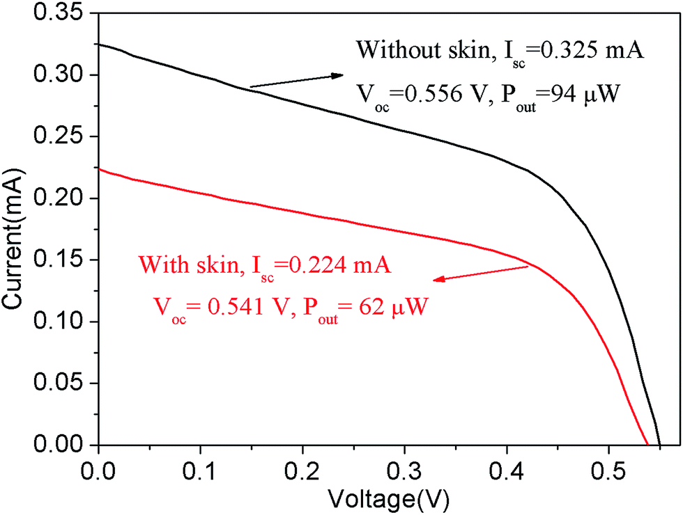 | ||
| Fig. 7 Photocurrent–voltage characteristics of 980LD-PC either uncovered or covered with chicken skin under the irradiation of a 980-nm laser (intensity: 720 mW cm−2, area: 0.25 cm2). | ||
Importantly, 980LD-PC covered by chicken skin still retains an excellent photoelectrical performance under the irradiation of a 980-nm laser (red line in Fig. 7). The photocurrent–voltage results show a slight decline for Voc at 0.538 V, while Isc (0.224 mA), Pout (62 μW) and η (0.034%) are reduced by nearly 35% compared with those in the absence of chicken skin. The reduction should be attributed to the absorption and reflection effect of chicken skin, the magnitude of which is similar to our previous reports.16 Furthermore, the electrical output (62 μW) is higher than that (22.2 μW) of our previous 980LD-PC based on DSSC,16 and it is also high enough to satisfy the power requirements of many biological devices, such as in vivo nanorobots (power: at least 1 μW) and cardiac pacemakers (power: about 10 μW). We also believe that the performance of the present 980LD-PC can be further enhanced by improving the up-converting luminescence of NaYF4:Yb,Er-PET composite film, amorphous silicon thin film photovoltaic cell, and the device structure. Although the present model of 980LD-PC still has a large area, it should be easily miniaturized by tailoring the NaYF4:Yb,Er-PET composite film and preparing flexible amorphous silicon thin film photovoltaic cells with small area, which is an ongoing process in our laboratory.
4. Conclusions
Hydrophobic NaYF4:Yb,Er nanorods with diameters of about 200 nm and lengths of 0.5–1 μm have been synthesized by a modified hydrothermal/solvothermal method at 200 °C for 30 h. Subsequently, NaYF4:Yb,Er-PET composite films (NaYF4:Yb,Er/PET weight ratio: 2.5–20%) have been synthesized by using film casting technology, and they exhibit excellent up-converting luminescence, flexibility and transparency. Based on a 20%NaYF4:Yb,Er-PET composite film and commercial flexible amorphous silicon film photovoltaic cell, we developed a novel model of 980LD-PC. Under the direct irradiation of a 980-nm laser (intensity: 720 mW cm−2, area: 0.25 cm2), 980LD-PC exhibits a maximum output power of 94 μW. Importantly, when 980LD-PC is covered with a chicken skin, it still retains the maximum output power of 62 μW which is high enough to satisfy the power requirements of in vivo nanorobots and cardiac pacemakers. Therefore, the present 980LD-PC has great potential to be used as a novel model for an all-solid-state flexible biopower component in biodevices which can be implanted under the human skin.Acknowledgements
This work was financially supported by the National Natural Science Foundation of China (Grant No. 21477019, 51272299, and 51473033), project of the Shanghai Committee of Science and Technology (13JC1400300), the Fundamental Research Funds for the Central Universities, and DHU Distinguished Young Professor Program.Notes and references
- J. Elbaz and I. Willner, Nat. Mater., 2012, 11, 276–278 CrossRef CAS PubMed.
- S. M. Douglas, I. Bachelet and G. M. Church, Science, 2012, 335, 831–834 CrossRef CAS PubMed.
- B. L. Allen, P. D. Kichambare and A. Star, Adv. Mater., 2007, 19, 1439–1451 CrossRef CAS.
- C. Z. Liao, C. Mak, M. Zhang, H. L. W. Chan and F. Yan, Adv. Mater., 2015, 27, 676–681 CrossRef CAS PubMed.
- G. A. Ozin, I. Manners, S. Fournier-Bidoz and A. Arsenault, Adv. Mater., 2005, 17, 3011–3018 CrossRef CAS.
- I. L. Medintz, A. R. Clapp, H. Mattoussi, E. R. Goldman, B. Fisher and J. M. Mauro, Nat. Mater., 2003, 2, 630–638 CrossRef CAS PubMed.
- L. Rodriguez-Lorenzo, R. de la Rica, R. A. Alvarez-Puebla, L. M. Liz-Marzan and M. M. Stevens, Nat. Mater., 2012, 11, 604–607 CrossRef CAS PubMed.
- X. Duan, Y. Li, N. K. Rajan, D. A. Routenberg, Y. Modis and M. A. Reed, Nat. Nanotechnol., 2012, 7, 401–407 CrossRef CAS PubMed.
- R. K. Soong, G. D. Bachand, H. P. Neves, A. G. Olkhovets, H. G. Craighead and C. D. Montemagno, Science, 2000, 290, 1555–1558 CrossRef CAS PubMed.
- H. Wang and M. Pumera, Chem. Rev., 2015, 115, 8704–8735 CrossRef CAS PubMed.
- J. Li, W. Gao, R. F. Dong, A. Pei, S. Sattayasamitsathit and J. X. Wang, Nat. Commun., 2014, 5, 5026–5032 CrossRef CAS PubMed.
- Z. Wu, Y. Wu, W. He, X. Lin, J. Sun and Q. He, Angew. Chem., Int. Ed., 2013, 52, 7000–7003 CrossRef CAS PubMed.
- W. Gao, D. Kagan, O. S. Pak, C. Clawson, S. Campuzano, E. Chuluun-Erdene, E. Shipton, E. E. Fullerton, L. Zhang, E. Lauga and J. Wang, Small, 2012, 8, 460–467 CrossRef CAS PubMed.
- H. L. Tierney, C. J. Murphy, A. D. Jewell, A. E. Baber, E. V. Iski, H. Y. Khodaverdian, A. F. McGuire, N. Klebanov and E. C. Sykes, Nat. Nanotechnol., 2011, 6, 625–629 CrossRef CAS PubMed.
- Z. G. Chen, L. S. Zhang, Y. G. Sun, J. Q. Hu and D. Y. Wang, Adv. Funct. Mater., 2009, 19, 3815–3820 CrossRef CAS.
- L. S. Zhang, Q. W. Tian, W. J. Xu, X. Y. Kuang, J. Q. Hu, M. F. Zhu, J. S. Liu and Z. G. Chen, J. Mater. Chem., 2012, 22, 18156–18163 RSC.
- X. Wang, J. Song, I. Liu and Z. L. Wang, Science, 2007, 316, 102–105 CrossRef CAS PubMed.
- H. Li, Y. Sang, S. Chang, X. Huang, Y. Zhang, R. Yang, H. Jiang, H. Liu and Z. L. Wang, Nano Lett., 2015, 15, 2372–2379 CrossRef CAS PubMed.
- G. Zhu, J. Chen, T. Zhang, Q. Jing and Z. L. Wang, Nat. Commun., 2014, 5, 3426–3434 Search PubMed.
- S. Xu, B.J. Hansen and Z. L. Wang, Nat. Commun., 2010, 1, 93–97 CrossRef PubMed.
- Z. Li, G. Zhu, R. Yang, A. C. Wang and Z. L. Wang, Adv. Mater., 2010, 22, 2534–2537 CrossRef CAS PubMed.
- Y. M. Yan, W. Zheng, L. Su and L. Q. Mao, Adv. Mater., 2006, 18, 2639–2643 CrossRef CAS.
- F. Gao, L. Viry, M. Maugey, P. Poulin and N. Mano, Nat. Commun., 2010, 1, 2–8 Search PubMed.
- A. Zebda, C. Gondran, A. Le Goff, M. Holzinger, P. Cinquin and S. Cosnier, Nat. Commun., 2011, 2, 370–375 CrossRef PubMed.
- T. Chen, S. C. Barton, G. Binyamin, Z. Gao, Y. Zhang, H.-H. Kim and A. Heller, J. Am. Chem. Soc., 2001, 123, 8630–8631 CrossRef CAS PubMed.
- J.-L. Wu, F.-C. Chen, M.-K. Chuang and K.-S. Tan, Energy Environ. Sci., 2011, 4, 3374–3378 CAS.
- K. Yoo, J. Y. Kim, J. A. Lee, J. S. Kim, D. K. Lee, K. Kim, J. Y. Kim, B. Kim, H. Kim, W. M. Kim, J. H. Kim and M. J. Ko, ACS Nano, 2015, 9, 3760–3771 CrossRef CAS PubMed.
- H. C. Weerasinghe, F. Huang and Y.-B. Cheng, Nano Energy, 2013, 2, 174–189 CrossRef CAS.
- X. Wang, J. Zhuang, Q. Peng and Y. D. Li, Nature, 2005, 437, 121–124 CrossRef CAS PubMed.
- Z. G. Chen, H. L. Chen, H. Hu, M. X. Yu, F. Y. Li, Q. Zhang, Z. G. Zhou, T. Yi and C. H. Huang, J. Am. Chem. Soc., 2008, 130, 3023–3029 CrossRef CAS PubMed.
- L. Y. Wang and Y. D. Li, Chem. Mater., 2007, 19, 727–734 CrossRef CAS.
- F. Wang, Y. Han, C. S. Lim, Y. Lu, J. Wang, J. Xu, H. Y. Chen, C. Zhang, M. H. Hong and X. G. Liu, Nature, 2010, 463, 1061–1065 CrossRef CAS PubMed.
- M. Wang, C. C. Mi, W. X. Wang, C. H. Liu, Y. F. Wu, Z. R. Xu, C. B. Mao and S. K. Xu, ACS Nano, 2009, 3, 1580–1586 CrossRef CAS PubMed.
- Y. Xu, D. Chen, X. Jiao and K. Xue, J. Phys. Chem. C, 2007, 111, 16284–16289 CAS.
- J. C. Boyer, F. Vetrone, L. A. Cuccia and J. A. Capobianco, J. Am. Chem. Soc., 2006, 128, 7444–7445 CrossRef CAS PubMed.
- F. J. Haug, T. Söderström, M. Python, V. Terrazzoni-Daudrix, X. Niquille and C. Ballif, Sol. Energy Mater. Sol. Cells, 2009, 93, 884–887 CrossRef CAS.
- J. R. Wilson, D. M. Mancini, K. McCully, N. Ferraro, V. Lanoce and B. Chance, Circulation, 1989, 80, 1668–1674 CrossRef CAS PubMed.
- American National Standard Institute, American National Standard for Safe Use of Lasers (ANSI Z136. 1-2000), Laser Institute of America, Orlando, FL, 2000 Search PubMed.
Footnote |
| † These authors contributed equally to the work. |
| This journal is © The Royal Society of Chemistry 2016 |