A 1-D coordination polymer route to catalytically active Co@C nanoparticles

Anand Pariyara, Siddharth Gopalakrishnanb, Joseph Stansberyb, Rajankumar L. Patelb, Xinhua Liangb, Nikolay Gerasimchukc and Amitava Choudhury*a
aDepartment of Chemistry, Missouri University of Science and Technology, Rolla 400 W 11th Street, Rolla, MO 65409, USA. E-mail: choudhurya@mst.edu; Fax: +1-573-341-6033; Tel: +1-573-341-6332
bDepartment of Chemical and Biochemical Engineering, Missouri University of Science and Technology, Rolla, MO 65409, USA
cDepartment of Chemistry, Missouri State University, Springfield, MO 65897, USA

Received 22nd February 2016 , Accepted 30th March 2016

First published on 8th April 2016


Abstract

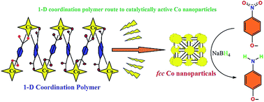
Pyrolysis of a 1-D polymeric cobalt(II) coordination complex ([Co(BDC)(Mim)2]n, H2BDC = benzenedicarboxylic acid; Mim = N-methylimidazole) results in the formation of carbon embedded fcc cobalt nanoparticle composites, Co@C. The as-prepared Co@C shows an agglomerated secondary structure with a highly embedded carbon shell comprising of cobalt nanoparticles of 20–100 nm. These Co@C particles show excellent catalytic activity in the reduction of nitrophenol to aminophenol, studied as a model reaction, and evolves as a promising candidate for the gas phase reduction process.

Introduction

Metal–Organic Frameworks (MOFs) have evolved as one of the fastest growing research areas in the last decade primarily because of their unique combination of porous structure and a variety of physicochemical properties.1–3 MOFs, also known as porous coordination polymers (PCPs), have found application in gas sorption, separation, catalysis, sensors, and drug deliveries to name a few.1–6 Recently another attribute of MOFs is catching everyone's attention. These MOFs when pyrolyzed under certain conditions can generate materials which are extremely good for catalysis and energy storage applications.7–9 These MOF-decomposed ‘left over’ residues are metal or metal oxide nanoparticles, and often these nanoparticles are embedded in a carbonaceous shell making them excellent candidates for catalysis and other applications.10–18 MOFs are crystalline solids made of ionocovalent interactions between the polydentate ligand (aromatic polycarboxylates or imidazolates etc.) and the metal polyhedra or a metal cluster creating a porous network, thus automatically qualifying as single-source-precursors for metal (M), metal oxide (MO) and carbon.7–18 This precursor route is easy, inexpensive and offers high tunability through easy variation of decomposition conditions. For these reasons investigation of MOF-derived composite materials for energy storage applications and catalysis are on the rise.7,8 For example, in case of Co-MOFs, Liu et al. formed Co3O4 nanoparticles from Co3(NDC)3(DMF)4 [NDC = 2,6-naphthalenedicarboxylate] MOF and used as a Li ion battery material.15 Wei et al. derived Co/C composite from Co-based ZIF-67 [Co(MeIm)2, MeIM = 2-methylimidazole] and found to be active supercapacitor electrode material.16 Torad et al. used the same ZIF-67 to derive nanoporous carbon embedded Co nanoparticles with suitable adsorbent property.17 Kong et al. formed Co nanocomposites via pyrolysis of a Co-MOF, CPM-24 [(CH3)2NH2]10[Co2(IN)4(Ac)2][Co2(BTC)2(H2O)]4[Co2(OH)(IN)3]4 (BTC = 1,3,5-benzenetricarboxylate; IN = isonicotinic acid; Ac = acetate) that shows excellent electrocatalytic activity for the oxygen reduction reaction (ORR) with an efficiency comparable to the commercial Pt/C catalyst.18 Design of such functional material for targeted applications through rational approaches would constitute important goals of this research. So far MOFs which are truly porous by virtue of three dimensionally connected covalent networks have been tested to obtain porous carbon or M/MO@C composites.7–21 However, there are porous two-dimensional (2-D) covalent networks, MOF-2 type,22 or one-dimensional (1-D) coordination polymers23 that are held together by non-covalent interactions in the remaining directions. These 2-D and 1-D coordination polymers are also highly susceptible to thermolysis even at lower temperatures, which in turn yield nanostructured M/MO.24–28 However, synthesis of such nanostructured M/MO@C or porous carbon as functional materials from 1-D coordination polymer is still lacking. The main challenge in coordination polymer synthesis is to establish the right synthetic conditions that eventually will lead to formation of defined inorganic building blocks with desired organic linker to form exclusively 1-D coordination polymer.29 We, therefore, sought to design and synthesize 1-D coordination polymer with aromatic ligands and examine its pyrolysis towards the formation of M/MO@C. Here, we present the synthesis of a Co(II) 1-D coordination polymer based on 1,4-benzenedicarboxylic acid (BDC) as linker in which a co-ligand N-methylimidazole (Mim) has been used to block the remaining coordination sites and their thermolysis for the generation of highly surface active magnetically separable Co@C reduction catalyst.

Experimental

Materials and physical methods

Cobalt nitrate (Co(NO3)2·6H2O), para-nitrophenol and sodium borohydride were purchased from Alfa Aesar. 1,4-Benzene dicarboxylic acid and 1-methyl imidazole were purchased from Sigma-Aldrich. All Chemicals and solvents were used as received unless otherwise mentioned. para-Nitrophenol was recrystallized twice from hot water before use.

Single-crystal X-ray diffraction (SCXRD) intensity data sets were collected on a Bruker Smart Apex diffractometer with monochromated Mo Kα radiation (0.7107 Å). Powder X-ray diffraction (PXRD) pattern was obtained from a PANalytical X'Pert Pro diffractometer equipped with a Cu Kα1,2 anode and a linear array PIXcel detector over a 2θ range of 5° to 90° with an average scanning rate of 0.0472° s−1. Thermogravimetric analysis (TGA) has been performed on the sample with a TA instrument Q50 TGA with a scan rate of 10 °C min−1 under N2 flow rate of 40 mL min−1. FT-IR spectrum was collected using Thermo Nicolet Nexus 470 FT-IR spectrometer over 400–4000 cm−1 on a sample embedded in KBr pellet. UV-Vis spectroscopy was performed in Varian CARY 100 Bio UV-Vis spectrophotometer. Temperature dependent UV-Vis spectra were recorded in 1 cm quartz cuvette (Starna) using the Agilent 8453 diode array spectrophotometer equipped with TC1 Peltier temperature controller by Quantum Northwest. Independent temperature control was provided by Cen-Tech 92242 digital thermometer with K-type probe. Scanning electron microscopy (SEM) images were taken using Helios Nanolab-600 equipped with Energy Dispersive Spectrometry (EDS) detector (Oxford Instrument) for elemental analysis. X-ray Photoelectron Spectrometry (XPS) was performed on a Kratos Axis 165 Photoelectron Spectrometer. The binding energies of all peaks were corrected as compared with reference peak of adventitious carbon (C1s, 284.8 eV).30 TEM images were obtained on FEI Tecnai F20 and Tecnai Osiris TEM operating at 200 kV. The as-pyrolized sample was dispersed in an acetone solution to prepare the TEM sample. A drop of the “as dispersed” solution was placed onto a carbon coated TEM grid and dried in air prior to TEM imaging and EDS. High resolution TEM was obtained with the Tecnai Osiris operated at 200 keV with a probe current of 2.5 nA. Raman measurement was performed in Horiba Jobin Yvon spectrometer using Nd:YAG laser with 30 s exposure time. Gas adsorption experiments were carried out in Quantachrome's Autosorb-1 surface area measurement instrument. Before the start of the gas-adsorption experiments, the as-prepared samples were outgassed at 120 °C under vacuum for 12 h. The specific surface areas of the samples were calculated using the Brunauer–Emmett–Teller (BET) method. The pore size distribution curves were derived from the adsorption and desorption isotherms using the Barrett–Joyner–Halenda (BJH) methods.

Synthesis

Synthesis of [Co(BDC)(Mim)2]n (1). Co(NO3)2·6H2O (0.2910 g, 1 mmol), 1,4-benzenedicarboxylate (0.1661 g, 1 mmol) and N-methylimidazole (0.18 mL, 2.26 mmol) were stirred with 8 mL of a DMF and EtOH solution (3[thin space (1/6-em)]:[thin space (1/6-em)]1 by volume) at room temperature. After all the solutes were dissolved, the solution was sealed in a HDPE bottle and placed in a preheated oven at 100 °C for 24 hours, giving dark purple crystals. The crystals were washed repeatedly with DMF followed by EtOH, to remove unreacted ligands/metal salts and dried in air. Yield = 42%. Analytically calculated for C16H16N4O4Co: C 49.62; H 4.16; N 14.47: found C 49.75; H 4.32; N 14.34. FT-IR (KBr, cm−1): 652, 739, 825, 1094, 1360, 1425, 1588, 2963 and 3125.

Synthesis of Co@C (2). The coordination polymer, 1 (0.5410 g) was taken in a heating boat and subjected to pyrolysis in a CVD furnace at 550 °C for 2 h under N2 gas with 50 SCCM flow rate. The sample was heated at a rate of 100 °C h−1 till 550 °C and held at that temperature for 2 h followed by cooling down to room temperature at the rate of 100 °C h−1. Such treatment yielded a black solid product (0.1550 g) with a weight loss of 76.8%. CHN elemental analysis C: 35.05%.

Crystal structure analysis of [Co(BDC)(Mim)2]n (1)

A suitable crystal of 1 was selected and mounted on a glass fiber using epoxy-based glue. The data were collected at 220 K employing a scan of 0.3° in ω with an exposure time of 20 s per frame. The data sets were collected using SMART software,31 the cell refinement and data reduction were carried out with SAINT,32 while the program SADABS32 was used for the absorption correction. The structure was solved by direct methods using SHELX-97 and difference Fourier syntheses.33 Full-matrix least-squares refinement against |F2| was carried out using the SHELXL-2014 using WINGX programs suite.33

Catalytic reduction of p-nitrophenol

All catalytic reduction reactions were performed at room temperature in air. In a typical reaction, 2 mg of 2 was added to 5 mL of 1 mM para-nitrophenol solution in water followed by freshly prepared 1 mL, 50 mM NaBH4 solution. The final concentration of para-nitrophenol and NaBH4 in the reaction mixture was 0.83 mM and 8.3 mM, respectively.

Results and discussion

1-D coordination polymer was designed by using 1,4-benzenedicarboxylic acid (BDC) as bridging ligand. Multicarboxylate ligands are widely used in the assembly of supramolecular architectures because of their diverse coordination modes to generate structures with various building blocks such as honeycomb, brick wall, rectangular grid, bilayer, ladder, diamond networks as well as open frameworks.22,29 To restrict the structure to grow strictly in 1 dimension, we have used N-methylimidazole (Mim) as a co-ligand to cap some of the coordination sites on the metal and make them unavailable for BDC. Interestingly, a reaction of equivalent amount of Co(II) nitrate and BDC in DMF/EtOH solvent mixture with 2 equiv. of Mim at 100 °C yielded a pure phase purple crystals suitable for single-crystal X-ray diffraction. The solid was found to be stable in air, water and organic solvents. The bulk purity of the product is evident by a good match of the experimental PXRD pattern with the one simulated from SCXRD (Fig. 1). The product crystallizes in triclinic, P[1 with combining macron] space group and shows the formation of polymeric coordination complex with [Co(BDC)(Mim)2]n (1) as a formula unit. Table 1 list the summary of the crystallographic data and the structure refinement results.
image file: c6ra04650a-f1.tif
Fig. 1 Experimental (as synthesized) and simulated (single crystal diffraction data) PXRD pattern of 1.
Table 1 Crystallographic data and structure refinement results for 1
Empirical formula C16H16N4O4Co
Formula weight (g mol−1) 387.26
Wavelength (Å) 0.71073
Crystal system Triclinic
Space group P[1 with combining macron]
a (Å) 7.3256 (7)
b (Å) 9.0006 (9)
c (Å) 13.7874 (14)
α (°) 82.0240 (10)
β (°) 78.2670 (10)
γ (°) 72.3450 (10)
Volume (Å3) 845.25 (15)
Z 2
Calculated density (mg m−3) 1.522
Goodness of fit on F2 1.056
Final R indices I > 2sigma R1 = 0.0426 wR2 = 0.1059
R indices (all data) R1 = 0.0503 wR2 = 0.1101
Largest diff. peak/hole 0.460/−0.240


The Co(II) in 1 adopts a tetrahedral coordination with two oxygen atoms from two BDC units in bis-monodentate (synanti) fashion along with two N-donors from two Mim units (Fig. 2a). The polymeric 1-D chain is propagated via bridging BDC connecting Co atoms in a zig–zag fashion (Fig. 2b). The Co1–Co1′–Co1′′ angle is 100.56(1)° and the distance between two Co centers is 10.74(8) Å and 10.94(7) Å depending on the oxygen it is bonded to, O1 for the former and O3 for the latter (Table S1, ESI). This is related to the fact that the Co1–O1 and the Co1–O3 bond lengths are 2.007(2) and 2.008(3) Å, respectively, which are typical for a tetrahedral Co(II) ion bonded to carboxylate ion.34 The Co(II) oxidation state is further supported by Co–N bond length of 2.029(2) Å (Co1–N1) and 2.056(2) Å (Co1–N3).34 Similar chain like structures are reported in other Cu, Zn and Ni complexes with bridged BDC where the M–M–M (M = metal) angles range between 65° to ideal 120° and are noted to be a function of steric contribution from the co-ligand.35–37 The 1-D polymeric complex 1 packs as infinite chains along a-axis via inter-chain hydrogen bonding to form 2-D array (Fig. 3a).


image file: c6ra04650a-f2.tif
Fig. 2 (a) View of the asymmetric unit of 1 with thermal ellipsoids given at 50% probability. (b) The zig–zag 1-D coordination polymer chain bridged through BDC. Hydrogen atoms are omitted for clarity. Color scheme: pink (cobalt), red (oxygen), blue (nitrogen) and grey (carbon).

image file: c6ra04650a-f3.tif
Fig. 3 (a) Packing diagram showing 2-D arrangement of the polymeric compound 1 through hydrogen bonds (shown by green dotted line). (b) C–H⋯π induced extensive 3-D network. Color scheme: pink (cobalt), red (oxygen), blue (nitrogen), grey (carbon) and light grey (hydrogen).

Two strong hydrogen bonding with donor (D)–acceptor (A) distances of 2.59 and 2.55 Å with D–H⋯A angles of 167 and 160°, respectively, for C10–H10A⋯O2 and C12–H12C⋯O1, were noted between the N-methyl hydrogens (Table S2, ESI) and the metal coordinated carboxylate oxygen. Furthermore, the 2-D layers give rise to 3-D supramolecular network (Fig. 3b) via C–H⋯π interactions (Table S3, ESI) as evident from short C–H⋯π distance of 2.83 to 2.93 Å. In FT-IR spectrum (Fig. S1, ESI), coordination of carboxylic group to the metal center is evident from the change of ν(C[double bond, length as m-dash]O) band to lower wavelength, from 1720 cm−1 in uncoordinated BDC to 1588 cm−1 in 1.35–38 The presence of Mim unit is also evident through characteristic peaks at 2963, 1425 and 1360 cm−1, known for coordinated Mim.38 Thermogravimetric analysis (TGA) reveals incremental loss, first, at 200 °C and an overall mass loss of 42.4% at a temperature of 400 °C, that can be accounted for the loss of both Mim moieties (Fig. S2, ESI) from the overall structure of 1. The decomposition of the Co-BDC backbone is therefore expected to decompose from temperature above 400 °C. Interestingly, PXRD of the calcined product of 1 after the TGA which was carried out up to 850 °C did not show any formation of oxides or carbides but metallic cobalt and the final weight (∼23%) found was slightly higher than required for just metallic cobalt (15.2%). This indicates retention of some chemical residues presumably carbon along with metallic cobalt. The polymeric complex 1 was then subjected to controlled pyrolysis under N2 in a CVD furnace. The synthesis was optimized at 550 °C and a dark carbonaceous solid Co@C (2) was formed. The PXRD of 2 revealed the formation of metallic fcc cobalt (Co0) phase (Fig. 4).39 It is to be noted that 2 is devoid of any conventional carbides of Co such as Co2C and Co3C, which may be due to lower decomposition temperature of Co2C (300 °C) and Co3C (315 °C).40 Elemental analysis of 2 prepared through five independent syntheses supports TGA results with carbon percentage between 35.07% and 35.36%, showing bulk carbonization of 2. This implies the presence of carbon along with the metallic cobalt phase. SEM image shows hierarchical near spherical carbonaceous aggregated metal clusters (Fig. 5).


image file: c6ra04650a-f4.tif
Fig. 4 PXRD pattern of as synthesized 2 (top, black line) is shown against literature reported metallic fcc Co39 (bottom, red line).

image file: c6ra04650a-f5.tif
Fig. 5 SEM image of as synthesized Co@C (2) collected with Au sputtering.

Furthermore, when a laboratory magnet was placed near a suspension of 2 in EtOH, almost quantitative collection of the content around the vicinity of the magnet was found within 2 min (Fig. S3, ESI). This strong interaction with magnet shows that the Co-metal particles are highly magnetic and the carbon is highly embedded on Co-particles. TEM image of 2 taken from dispersion of ethanolic solution shows cobalt particles of 20–100 nm size highly embedded in carbon shell (Fig. 6a). Based on the mass contrast as shown in Fig. 6b on a single cobalt nanoparticle, the light contrast can be assigned to carbon rich materials and the dark contrast to the cobalt core. The dark domain is highly single-crystalline as evident from the SAED pattern which can be indexed to fcc cobalt while the shell around it is amorphous (Fig. S4, ESI). The TEM micrograph shows the presence of domains of graphitic carbon (Fig. S5, ESI) around the cobalt particles as evident from analysis of the lattice fringes with d-spacing of 0.34 nm (Fig. 6b). It is also noticeable that the thickness of the carbon shell is not uniform and varies from 5 to 8 nm. The presence of carbon coating is further supported by Raman spectroscopy of 2 which shows two signature bands at 1364 and 1587 cm−1 for D and G bands of disordered and graphitic carbon, respectively (Fig. 7).19,41 Furthermore, XPS analysis of 2 (Fig. S6, ESI) done without Ar ion sputtering exhibited Co 2p3/2 peak at 778.3 eV characteristic of zero-valent metallic cobalt.42 However, peak at 781.3 eV along with shake-up satellite peaks for Co(II) species was also found. Since PXRD excludes the possibility of crystalline Co(II) species, the observed Co(II) indicates oxidation of reactive metallic cobalt surface to CoO, such slow oxidation in air has been observed previously for Co nanoparticles.17


image file: c6ra04650a-f6.tif
Fig. 6 (a) TEM image of as synthesized 2 showing Co particles embedded by graphitic and amorphous carbon. (b) TEM micrograph along the boundary region showing the presence of graphitic carbon shell over cobalt particles evident from analysis of the lattice fringes.

image file: c6ra04650a-f7.tif
Fig. 7 Raman spectra for Co@C (2) designating the D (1364 cm−1) and G (1587 cm−1) band (IG/ID = 0.37).

The suitability of 2 as a catalyst was evaluated as cobalt particles are very well known for catalytic applications. As a model reaction, the hydrogenation of para-nitrophenol (PNP) to para-aminophenol (PAP) at room temperature was performed to test the catalytic activity of 2 (Scheme 1). PNP and other nitro phenol derivatives are common byproducts of pesticides, herbicides, and synthetic dye productions and the reaction is a strong indicator for catalytic potential.43


image file: c6ra04650a-s1.tif
Scheme 1 Schematic presentation of conversion of PNP to PAP.

Preliminary reaction of PNP with 5 mol% of 2 using 20 eq. NaBH4 (2[thin space (1/6-em)]:[thin space (1/6-em)]PNP[thin space (1/6-em)]:[thin space (1/6-em)]NaBH4 = 1[thin space (1/6-em)]:[thin space (1/6-em)]20[thin space (1/6-em)]:[thin space (1/6-em)]400) in H2O at 20 °C gave quantitative conversion to PAP (Fig. S7, ESI). For comparison, identical reaction without 2 (blank) or with 1 shows almost no or negligible PNP conversion which indicates the indispensable role of 2 for the conversion. Careful literature review shows ample use of carbon or silica supported metal particles for the catalytic conversion of PNP to PAP and almost all reports show that the support such as carbon, graphene oxide, silica or alumina augments the catalytic property of the material but themselves (support) are inactive (Table S4, ESI).44–49 For example, the catalytic activity of carbon as in carbon nanotube with surface area as high as 176.7 m2 g−1 (Table S4, entry 1, ESI) show extremely sluggish rate (Kapp = 0.001 min−1) for the reduction of nitrophenol to aminophenol and can be considered as almost inactive.44 Fig. 8 shows the reduction of PNP through the decrease in absorbance maxima at 400 nm due to the nitro functionality and the generation of PAP as indicated by the gradual emergence of peak intensity at 300 nm due to the amine functionality. Furthermore, kinetic measurements were performed by monitoring the decrease in absorbance at 400 nm with a molar ratio of 2[thin space (1/6-em)]:[thin space (1/6-em)]PNP[thin space (1/6-em)]:[thin space (1/6-em)]NaBH4 = 1[thin space (1/6-em)]:[thin space (1/6-em)]102[thin space (1/6-em)]:[thin space (1/6-em)]105 (catalyst = 0.375 μM).43–51 The ln(A/Ao) vs. time plotted in Fig. 8 (Inset) depicts negligible change in absorbance at 400 nm in the absence of catalyst (blank). On the other hand, upon addition of 2, a certain period of time was required for the reaction to start. Under limiting NaBH4 concentration, pseudo-first order kinetics with respect to PNP is applied to the kinetic data.43–51 The slope of near linear fit plot of the natural log of absorbance at 400 nm versus time (inset Fig. 8, red line) gives the apparent rate constant43–50 (Kapp = 0.31 ± 0.02 min−1). Under the given reaction condition, the induction period (t0) is 1.6 minutes for three independent kinetic measurements at 20 °C. It was noted that the induction period is independent of the concentration of NaBH4 and depends strongly on PNP concentration. This finding points to the fact that PNP restructuring over the active catalytic center dictates the induction period. Lowering of the induction time over higher temperature further supports substrate (PNP) induced surface restructuring necessary for the catalytic activity of Co@C composites.43 The activation energy measured between 20 and 50 °C for the catalytic process is calculated to be 24.97 kJ mol−1 (Fig. S8, ESI) and is relatively lower than earlier reported Co/Ni nanoparticles (25.7–27.8 kJ mol−1)52,53 but relatively higher than Pt-cubes (12 kJ mol−1)54 (Table S5, ESI).52–58 As shown in Fig. 9 the N2 adsorption–desorption isotherm of the composite Co@C (2) follow type IV isotherm with a type H3 hysteresis loop. A type IV adsorption–desorption isotherms typically indicate the presence of mesopores (pore diameter, 2–50 nm) and a type H3 hysteresis loop is often correlated with slit-shaped pores due to assemblage of non-rigid plate-like particles.59


image file: c6ra04650a-f8.tif
Fig. 8 Catalytic reduction of PNP studied by UV-Vis with increment of time. Inset: plot of natural log of A/Ao vs. time showing the apparent rate constant36,37 marked by red line.

image file: c6ra04650a-f9.tif
Fig. 9 The N2 adsorption (black) and desorption (red) isotherm of Co@C (2) at 77 K.

The BET surface area of composite Co@C (2) is calculated to be 128 m2 g−1 with a pore volume of 0.4261 cm3 g−1 measured using N2 adsorption. The pore size distribution as obtained from the desorption isotherm of the composite yielded an average diameter of 4 nm (Fig. S9, ESI) calculated using the BJH method.60 The catalytic activity of 2 can be explained by considering the reaction at the metal surface where the presence of porous yet conformal coating around cobalt nanoparticle allows easy and control access of substrates to the active metal center. This is also indirectly substantiated by the reaction of PNP in presence of non-porous parent Co(II)-polymer, 1 (SABET = 23.82 m2 g−1) as catalyst. The reaction produced negligible product (Fig. S7, ESI) elaborating the role of the porous carbon shell around the metallic Co particles on the activity of the overall catalytic system. Although 3-D porous MOFs are well-known to play crucial role in producing uniform distribution of metal particles in a nano-porous carbonaceous matrix,7,8 in this article we showed that Co nanoparticles can be produced from 1-D non-porous coordination polymer with sufficient porosity and surface area making it a good candidate for catalyst.

Conclusions

In summary, the work presents an easy pathway for the generation of carbon coated fcc cobalt nanoparticles, Co@C, 2, through decomposition of polymeric 1-D coordination polymer. The facile reduction of PNP to PAP using NaBH4 with 2 shows the active nature of the material. The presence of catalytically active metallic particles with strong adsorption property, makes it a promising candidate for use in LT Fisher Tropsch synthesis (FTS).61 The absence of conventional cobalt carbides, known to be responsible for deactivation process in FTS, further enhances its suitability as a catalyst for the reaction and its study is currently been pursued by the group.

Acknowledgements

The authors acknowledge the funding from Materials Research Centre (Missouri S&T). The authors would like thank Professor Brow, Missouri S&T, for the use of Raman spectrometer.

Notes and references

  1. N. W. Ockwig, O. D. Friedrichs, M. O'Keeffe and O. M. Yaghi, Acc. Chem. Res., 2005, 38, 176–182 CrossRef CAS PubMed.
  2. R. J. Kuppler, D. J. Timmons, Q. R. Fang, J. R. Li, T. A. Makal, M. D. Young, D. Yuan, D. Zhao, W. Zhuang and H. C. Zhou, Coord. Chem. Rev., 2009, 253, 3042–3066 CrossRef CAS.
  3. G. Férey, Chem. Soc. Rev., 2008, 37, 191–214 RSC.
  4. H. Furukawa, K. E. Cordova, M. O'Keeffe and O. M. Yaghi, Science, 2013, 341, 1230444 CrossRef PubMed.
  5. S. Kitagawa, R. Kitaura and S. Noro, Angew. Chem., Int. Ed., 2004, 43, 2334–2375 CrossRef CAS PubMed.
  6. J. Y. Lee, O. K. Farha, J. Roberts, K. A. Scheidt, S. B. T. Nguyen and J. T. Hupp, Chem. Soc. Rev., 2009, 38, 1450–1459 RSC.
  7. J.-K. Sun and Q. Xu, Energy Environ. Sci., 2014, 7, 2071–2100 CAS.
  8. W. Xia, A. Mahmood, R. Zou and Q. Xu, Energy Environ. Sci., 2015, 8, 1837–1866 CAS.
  9. Y. Song, X. Li, L. Sun and L. Wang, RSC Adv., 2015, 5, 7267–7279 RSC.
  10. H. B. Wu, B. Y. Xia, L. Yu, X. Y. Yu and X. W. Lou, Nat. Commun., 2015, 6(1–8), 6512 CrossRef CAS PubMed.
  11. H. L. Jiang, B. Liu, Y. Q. Lan, K. Kuratani, T. Akita, H. Shioyama, F. Zong and Q. Xu, J. Am. Chem. Soc., 2011, 133, 11854–11857 CrossRef CAS PubMed.
  12. W. Chaikittisilp, N. L. Torad, C. Li, M. Imura, N. Suzuki, S. Ishihara, K. Ariga and Y. Yamauchi, Chem.–Eur. J., 2014, 20, 4217–4221 CrossRef CAS PubMed.
  13. N. L. Torad, M. Hu, Y. Kamachi, K. Takai, M. Imura, M. Naitoa and Y. Yamauchi, Chem. Commun., 2013, 49, 2521–2523 RSC.
  14. H. L. Jiang, B. Liu, Y. Q. Lan, K. Kuratani, T. Akita, H. Shioyama, F. Zong and Q. Xu, J. Am. Chem. Soc., 2011, 133, 11854–11857 CrossRef CAS PubMed.
  15. B. Liu, X. Zhang, H. Shioyama, T. Mukai, T. Sakai and Q. Xua, J. Power Sources, 2010, 195, 857–861 CrossRef CAS.
  16. F. Wei, J. Jiang, G. Yu and Y. Sui, Mater. Lett., 2015, 146, 20–22 CrossRef CAS.
  17. N. L. Torad, M. Hu, S. Ishihara, H. Sukegawa, A. A. Belik, M. Imura, K. Ariga, Y. Sakka and Y. Yamauchi, Small, 2014, 10, 2096–2107 CrossRef CAS PubMed.
  18. A. Kong, C. Mao, Q. Lin, X. Wei, X. Bu and P. Feng, Dalton Trans., 2015, 44, 6748–6754 RSC.
  19. S. J. Yang, S. Nam, T. Kim, J. H. Im, H. Jung, J. H. Kang, S. Wi, B. Park and C. R. Park, J. Am. Chem. Soc., 2013, 135, 7394–7397 CrossRef CAS PubMed.
  20. X. Xu, R. Cao, S. Jeong and J. Cho, Nano Lett., 2012, 12, 4988–4991 CrossRef CAS PubMed.
  21. W. Chaikittisilp, N. L. Torad, C. Li, M. Imura, N. Suzuki, S. Ishihara, K. Ariga and Y. Yamauchi, Chem.–Eur. J., 2014, 20, 4217–4221 CrossRef CAS PubMed.
  22. M. E. Braun, C. D. Steffek, J. Kim, P. G. Rasmussen and O. M. Yaghi, Chem. Commun., 2001, 2532–2533 RSC.
  23. W. L. Leong and J. J. Vittal, Chem. Rev., 2011, 111, 688–764 CrossRef CAS PubMed.
  24. S. Jung, W. Cho, H. J. Lee and M. Oh, Angew. Chem., Int. Ed., 2009, 48, 1459–1462 CrossRef CAS PubMed.
  25. Y. Xiong, Z. Li, R. Zhang, Y. Xie, J. Yang and C. Wu, J. Phys. Chem. B, 2003, 107, 3697–3702 CrossRef CAS.
  26. Z. Li, Y. Xiong and Y. Xie, Nanotechnology, 2005, 16, 2303–2308 CrossRef CAS PubMed.
  27. F. Zhang, F.-L. Bei, J.-M. Cao and X. Wang, J. Solid State Chem., 2008, 181, 143–149 CrossRef CAS.
  28. M. Y. Masoomi and A. Morsali, Coord. Chem. Rev., 2012, 256, 2921–2943 CrossRef CAS.
  29. T. R. Cook, Y. R. Zheng and P. J. Stang, Chem. Rev., 2013, 113, 734–777 CrossRef CAS PubMed.
  30. D. Briggs and M. P. Sech, Practical Surface Analysis, Wiley, New York, USA, 1983, p. 119 Search PubMed.
  31. Bruker, SMART, Bruker AXS Inc., Madison, Wisconsin, USA, 2002 Search PubMed.
  32. Bruker, SAINT and SADABS, Bruker AXS Inc., Madison, Wisconsin, USA, 2008 Search PubMed.
  33. G. M. Sheldrick, Shelxl, Acta Crystallogr., Sect. A: Found. Crystallogr., 2008, 64, 112–122 CrossRef CAS PubMed.
  34. X. Li, X. Sun, X. Li and X. Xu, New J. Chem., 2015, 39, 6844–6853 RSC.
  35. Y. B. Go, X. Wang, E. V. Anokhina and A. J. Jacobson, Inorg. Chem., 2004, 43, 5360–5367 CrossRef CAS PubMed.
  36. Y. J. Song, P. Zhang, J. W. Ji and Z. B. Han, Russ. J. Coord. Chem., 2009, 35, 698–703 CrossRef CAS.
  37. L. N. Zhu, L. Z. Zhang, W. Z. Wang, D. Z. Liao, P. Cheng, Z. H. Jiang and S. P. Yan, Inorg. Chem. Commun., 2002, 5, 1017–1021 CrossRef CAS.
  38. D. Cheng, M. A. Khan and R. P. Houser, J. Chem. Soc., Dalton Trans., 2002, 4555–4560 RSC.
  39. E. A. Owen and D. M. Jones, Proc. Phys. Soc., London, 1954, 67, 456–466 CrossRef.
  40. Z. J. Huba and E. E. Carpenter, Dalton Trans., 2014, 43, 12236–12242 RSC.
  41. F. Tuinstra and J. L. Koenig, J. Chem. Phys., 1970, 53, 1126–1130 CrossRef CAS.
  42. M. C. Biesinger, B. P. Payne, A. P. Grosvenor, L. W. M. Lau, A. R. Gerson and R. S. C. Smart, Appl. Surf. Sci., 2011, 257, 2717–2730 CrossRef CAS.
  43. J. Zeng, Q. Zhang, J. Chen and Y. Xia, Nano Lett., 2010, 10, 30–35 CrossRef CAS PubMed.
  44. X. Gu, W. Qi, X. Xu, Z. Sun, L. Zhang, W. Liu, X. Pan and D. Su, Nanoscale, 2014, 6, 6609–6616 RSC.
  45. S. Tang, S. Vongehr and X. Meng, J. Mater. Chem., 2010, 20, 5436–5445 RSC.
  46. R. Nie, J. Wang, L. Wang, Y. Qin, P. Chen and Z. Hou, Carbon, 2012, 50, 586–596 CrossRef CAS.
  47. J. Guo and K. S. Suslick, Chem. Commun., 2012, 48, 11094–11096 RSC.
  48. J. Lee, J. C. Park and H. Song, Adv. Mater., 2008, 20, 1523–1528 CrossRef CAS.
  49. N. Yan, Z. Zhao, Y. Li, F. Wang, H. Zhong and Q. Chen, Inorg. Chem., 2014, 53, 9073–9079 CrossRef CAS PubMed.
  50. Z. D. Pozun, S. E. Rodenbusch, E. Keller, K. Tran, W. Tang, K. J. Stevenson and G. Henkelman, J. Phys. Chem. C, 2013, 117, 7598–7604 CAS.
  51. Y. Lu, Y. Mei, M. Drechsler and M. Ballauff, Angew. Chem., Int. Ed., 2006, 45, 813–816 CrossRef CAS PubMed.
  52. N. Sahiner, H. Ozay, O. Ozay and N. Aktas, Appl. Catal., A, 2010, 385, 201–207 CrossRef CAS.
  53. N. Sahiner, H. Ozay, O. Ozay and N. Aktas, Appl. Catal., B, 2010, 101, 137–143 CrossRef CAS.
  54. M. A. Mahmoud, B. Snyder and M. A. El-Sayed, J. Phys. Chem. Lett., 2010, 1, 28–36 CrossRef CAS.
  55. N. Pradhan, A. Pal and T. Pal, Colloids Surf., B, 2002, 196, 247–257 CrossRef CAS.
  56. K. Kuroda, T. Ishida and M. Haruta, J. Mol. Catal. A: Chem., 2009, 298, 7–11 CrossRef CAS.
  57. S. Saha, A. Pal, S. Kundu, S. Basu and T. Pal, Langmuir, 2010, 26, 2885–2893 CrossRef CAS PubMed.
  58. S. Arora, P. Kapoor and M. L. Singla, React. Kinet., Mech. Catal., 2010, 99, 157–165 CAS.
  59. K. S. W. Sing, D. H. Everett, R. A. W. Haul, L. Moscou, R. A. Pierotti, J. Rouquerol and T. Siemieniewska, Pure Appl. Chem., 1985, 57, 603–619 CrossRef CAS.
  60. E. P. Barrett, L. G. Joyner and P. P. Halenda, J. Am. Chem. Soc., 1951, 73, 373–380 CrossRef CAS.
  61. B. Todic, V. V. Ordomsky, N. M. Nikacevic, A. Y. Khodakov and D. B. Bukur, Catal. Sci. Technol., 2015, 5, 1400–1411 CAS.

Footnote

Electronic supplementary information (ESI) available: Tables for crystallographic details and interaction for 1; cif file for 1; IR, TGA, XPS and other details. CCDC 1436062. For ESI and crystallographic data in CIF or other electronic format see DOI: 10.1039/c6ra04650a

This journal is © The Royal Society of Chemistry 2016