DOI:
10.1039/C6RA04102G
(Paper)
RSC Adv., 2016,
6, 60200-60205
Tribological performance and thermal conductivity of graphene–Fe3O4/poly(phenol-formaldehyde resin) hybrid reinforced carbon fiber composites
Received
15th February 2016
, Accepted 2nd June 2016
First published on 3rd June 2016
Abstract
Poly(phenol-formaldehyde resin)/carbon fiber composites with different ratios of graphene–Fe3O4 were manufactured through a molding press process. Fe3O4 was introduced into the graphene to avoid recombination of the layers. The effects of the amount of added graphene–Fe3O4 on the morphology, thermal conductivity, friction performance and thermal properties of the composites were investigated via scanning electron microscopy, thermal constants analysis, tribology and thermogravimetric tests. Scanning electron microscopy confirmed the enhanced friction surface of the composites and the combination of the resin with the fibers. The thermal conductivity measurements showed that the best results were achieved with 2.0 wt% graphene–Fe3O4. The friction coefficient and wear rate also decreased with the addition of graphene–Fe3O4 based on the tribological results.
1. Introduction
Friction material composites are widely used in the automotive, rail and aerospace industries as brake materials because of their excellent properties, including a moderate friction coefficient, low wear and reliable strength under different operating conditions.1,2 Friction materials generally fall into one of four different classes, namely, binders, reinforcements, fillers and friction modifiers. According to the specific demands of the application, the performance of the composites can be tuned by varying the relative amounts of the four components. Poly(phenol-formaldehyde resin) (PF), used as a binder, is one of the main friction matrices as a result of its low cost, thermal stability, structural integrity and good resistance.3–5 Carbon fibers (CFs), glass fibers and aramid fibers are used as reinforcement fibers in friction materials. Compared with other fibers, CFs have a superior performance, with extremely high strength, heat resistance and a high modulus.6 Resin-based CF friction materials are extensively utilized in the automobile, machinery and aerospace industries.7–10 Fillers, such as graphite, BaSO4 and CaCO3, have a crucial role in tuning the friction performance of composites, although the amounts used are small relative to those of the binder and reinforcements. Friedrich et al.11 have reported that various fillers reduced the sliding wear of polymer composites, whereas Park et al.12 mixed carbon black and PEEK powder in composites to enhance their wear characteristics.
Much research has been carried out on graphene because of its remarkably high thermal conductivity, large specific surface area and superior electronic conduction.13–17 Functionalized graphene has been introduced into polymers to meet the requirements of particular applications. Graphene has been reported to improve the friction, wear properties and thermal conductivity of materials such as epoxy,18 phenol polymers,19,20 polystyrene,21 polyimide,22,23polypropylene24 and poly(ether ether ketone).25 Liu et al.26 showed that surface-functionalized reduced graphene oxide in bismaleimide composites has a high tribological performance and good thermal stability. Cao and coworkers27 reported the improved lithium storage and magnetic properties of graphene–Fe3O4 composites. We have previously reported that graphene additives help to improve the thermal conductivity and friction performance of PEEK.28 However, the tribological properties of functionalized graphene/CF composites have rarely been studied. One of the challenges of such a process is the dispersion of particles into the polymer matrix. Zheng and coworkers29 reported multifunctional polyetherimide/graphene@Fe3O4 composite foams that could form a shield against electromagnetic pollution. We speculated that magnetic particles used as an additive could form a barrier between the graphene layers and avoid recombination of the graphene layers. We report here a facile strategy for the fabrication of functionalized graphene–Fe3O4 nanoparticles (G@Fe3O4) and an investigation of the thermal conductivity of the composites. The introduction of Fe3O4–graphene into PF/CF composites showed not only improved dispersion, but also a better tribological performance and thermal properties.
2. Materials and methods
2.1. Materials
Phenol (99%) and formaldehyde solutions (37%) were purchased from Shanghai Aladdin Bio-Chem Technology Co., Ltd, China. The CFs (T300, d25°C = 1.7 g cm−3) were supplied by Sinosteel Engineering & Technology Co. Ltd (China). Natural graphite and Fe(NO3)3 were supplied by Shanghai National Medicine Group Chemical Reagent Co. Ltd, China. The CF fabric was knitted using an automatic sampling loom (Evergreen, CCI TECH Inc., Taiwan).
2.2. Synthesis of functionalized graphene–Fe3O4 nanoparticles (G@Fe3O4)
GO was prepared from natural graphite powder using the Hummers method.30 The graphene–Fe3O4 nanoparticles were prepared by hydrothermal synthesis. The weight ratio in the reaction was 0.1 g GO to 1.0 g Fe(NO3)3 to 1.5 g ascorbic acid. These reagents were ultrasonically dispersed in 100 ml of deionized water for 60 min. Hydrazine hydrate was then added to the aqueous solution with magnetic stirring for 60 min. After stirring, the homogeneous solution was transferred into a Teflon-lined stainless-steel autoclave and heated at 180 °C for 8 h in a vacuum drying oven, followed by cooling naturally to room temperature. The resulting black precipitate was rinsed with deionized water and absolute alcohol and freeze-dried before further use.
2.3. Manufacture of PF/G@Fe3O4/CF composites
Different mass fractions (0–4.0 wt% loading) of G@Fe3O4 nanoparticles were dispersed in an ethanol solution containing PF with ultrasonication for 30 min. The mixture was stored under vacuum at 60 °C to remove the ethanol solvent. About 10.0 g of the obtained PF/G@Fe3O4 was used to presoak one layer of CF fabric. The composites were prepared using a mold press at 165 °C with 0.5 MPa pressure. The weight, size and thickness of each piece of CF fabric with PF/G@Fe3O4 were regulated, thus the PF/G@Fe3O4/CF composites had a uniform distribution of CFs and matrix. The PF/G@Fe3O4/CF fabric was dried in a vacuum oven at 30 °C for 30 min before the manufacturing procedure to reduce the amount of air bubbles. The synthetic approach for the preparation of G@Fe3O4 and the manufacture of the G@Fe3O4/CF composites is shown in Fig. 1.
 |
| | Fig. 1 Schematic representation of the synthetic procedure for the preparation of G@Fe3O4 and the manufacture of the composites. | |
2.4. Characterization
X-ray diffraction analysis. X-ray diffraction (XRD) analyses of the samples were carried out using a Shimadzu-6000 X-ray diffractometer with Cu Kα radiation (λ = 1.54056 Å) operated at 40 kV and 50 mA.
Thermogravimetric analysis. The thermal stability of the composites was determined by thermogravimetric analysis (TGA) (Mettler Toledo TGA 2). The samples were heated from 30 to 900 °C at a heating rate of 10 K min−1. Experiments were carried out on samples with an average mass of 10.0 mg and the samples were cut longitudinally from the center of the composites.
Morphological analysis. Scanning electron microscopy (SEM) (JSM-5600, JEOL, Japan) was used to investigate the worn surfaces and the fracture surfaces of the composites after coating the samples with a thin layer of gold.
Thermal conductivity measurements. The thermal conductivity of each composite was measured using a thermal constants analyzer (Hot Disk 2200, Hot Disk, Sweden) based on the transient plane source method. The samples were 60 × 60 × 1 mm in size and the sensor was placed between two equivalent slabs of the sample. The sensor supplied a heat pulse of 50 mW for 10 s and the experimental data were recorded.
Friction and wear tests. A universal tribo-tester (MVF-1A, Jinan Heng xu Testing Machine Technology Co. Ltd, China) was used to evaluate the friction behavior of the composites, which was of the rotating end-face friction type. The contact area was 125 mm2 and the slide speed was 0.278 m s−1 under a load of 100 N under ambient conditions for 60 min. Before each test, the samples and the plain carbon steel ring were cleaned with ethanol. The specific wear rate was calculated using the equation:
where Δm is the mass loss, ρ is the density of the composite, Fn is the applied load and L is the sliding distance.
3. Results and discussion
3.1. Crystalline structure
X-ray diffraction was used to determine the chemical composition and crystallographic structure of the materials (Fig. 2). In the original graphite sample, the characteristic diffraction peak (002) appeared at around 2θ = 26.3° (Fig. 2, line a). After oxidation, this diffraction peak shifted to around 10.3° (Fig. 2, line b), indicating oxidized graphite with oxygen-containing functional groups on the graphite sheets, i.e. the formation of GO, similar to previously reported results.32 Fig. 2 (line c) shows the diffraction peak for Fe3O4. The XRD pattern of the as-prepared G@Fe3O4 nanocomposites (Fig. 2, line d) matched the structure for magnetite (Fe3O4). The crystallographic structure confirmed that we had obtained the desired nanoparticles.
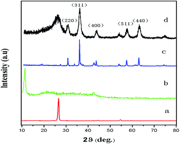 |
| | Fig. 2 X-ray diffraction patterns of samples: (a) natural graphite, (b) GO, (c) Fe3O4 and (d) G@Fe3O4 nanoparticles. | |
3.2. Morphological analysis
SEM was used to characterize the prepared G@Fe3O4. Fig. 3a shows the 2D structure of graphene with its characteristic crumpling, which indicated that the graphene morphology was well preserved during modification with Fe3O4. The SEM image also suggests that magnetite nanobeads appeared on the graphene surface after the hydrothermal reaction, as reported previously.31 To assess the dispersion of the G@Fe3O4 nanoparticles in the fabricated composites, the surface of the PF/2.0 wt% G@Fe3O4/CF composites were examined by SEM. Fig. 3b shows an SEM image of the PF/2.0 wt% G@Fe3O4/CF composites, which shows that the PF matrix permeated into the CFs and uniformly coated them. The circle in Fig. 3c shows the conglobation of G@Fe3O4 particles in PF, indicating that the addition of 4 wt% or more of G@Fe3O4 particles might lead to aggregation.
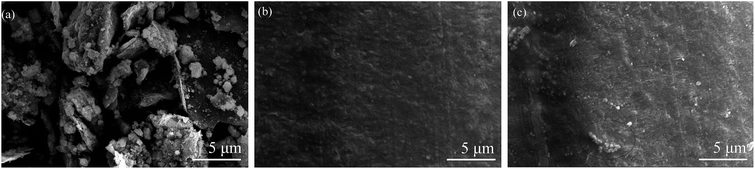 |
| | Fig. 3 (a) SEM image of G@Fe3O4. SEM images of the surface of the PF/CF composites: (b) 2 wt% G@Fe3O4 and (c) 4.0 wt% G@Fe3O4. | |
3.3. Thermogravimetric analysis
TGA measurements were carried out to evaluate the effect of G@Fe3O4 on the stability of the PF/CF composites; the corresponding thermogravimetric curves are shown in Fig. 4. The initial degradation temperature (Ti) and the second loss temperature (Ts) for the PF/CF and PF/G@Fe3O4/CF composites are given in Table 1. Fig. 4 shows the effects of the G@Fe3O4 content on the decomposition temperature of the PF/CF composites. The initial decomposition temperature of the composites increased with the G@Fe3O4 content, in agreement with the well-known fact that inorganic particles improve the heat resistance of composite materials reinforced with G@Fe3O4. The Ti for the PF/CF composites was 140.2 °C, whereas the Ti for the PF/2.0 wt% G@Fe3O4/CF composites increased to 171.9 °C. However, there was no obvious change in the second loss decomposition temperature. The impact properties of the PF/G@Fe3O4/CF composites might be a result of the decomposition of the characteristic structure of PF. Fig. 4 shows that the amount of residue at 800 °C increased with the amount of the G@Fe3O4 dopant. For example, the residual amount of pristine PF/CF was around 77%, while the residual amounts of PF/0.5 wt% G@Fe3O4/CF and PF/4.0 wt% G@Fe3O4/CF were 82 and 84%, respectively, which was consistent with our design. The decomposition stage of PF/1.0 wt% G@Fe3O4/CF and PF/2 wt% G@Fe3O4/CF showed obvious differences from those of PF/0.5 wt% G@Fe3O4/CF and PF/4.0 wt% G@Fe3O4/CF, although the residual amounts were fairly similar. It is reasonable to assume that the increase in thermal stability can be ascribed to strong interactions between the PF matrix and the G@Fe3O4. The strong interaction between the filler and the matrix hindered the segmental motion of the polymer chains and restricted the thermal mobility of the PF chains near the G@Fe3O4 surface. In addition, the significantly enhanced thermal conductivity of the composites can increase their thermal stability. In accordance with the morphology studies, redundant G@Fe3O4 did not have a major effect on improving the thermal stability as a result of the inhomogeneity of the aggregated G@Fe3O4.
 |
| | Fig. 4 TGA thermogram of PF/CF composites with different G@Fe3O4 contents. | |
Table 1 Thermal properties of PF/G@Fe3O4/CF compositesa
| Sample |
Ti (°C) |
Ts (°C) |
| Ti and Ts are the initial decomposition temperature and the second decomposition stage temperature, respectively. |
| PF/CF |
140.2 |
354.5 |
| PF/0.5 wt% G@Fe3O4/CF |
146.3 |
357.0 |
| PF/1.0 wt% G@Fe3O4/CF |
163.3 |
364.9 |
| PF/2.0 wt% G@Fe3O4/CF |
171.9 |
362.0 |
| PF/4.0 wt% G@Fe3O4/CF |
179.6 |
349.9 |
3.4. Friction behavior
The evolution of the friction coefficients of the composites was examined by a tribological test. Fig. 5a shows the evolution of the friction coefficients of the PF/G@Fe3O4/CF composites as a function of the sliding time. The incorporation of G@Fe3O4 obviously reduced the friction coefficient of the composites. It was shown that, when increasing the G@Fe3O4 content from 0 to 4.0 wt%, the friction coefficient first gradually decreased and then increased when the content of dopant was >2.0 wt%. Fig. 5b shows the mean friction coefficients of the composites with different contents of G@Fe3O4 under the same applied conditions. The mean friction coefficient of the composites was decreased by the incorporation of the G@Fe3O4 nanoparticles. The friction coefficient reached a minimum at 2.0 wt% G@Fe3O4.
 |
| | Fig. 5 (a) Evolution of friction coefficients of PF/CF and PF/G@Fe3O4/CF composites; (b) mean friction coefficients of composites as a function of G@Fe3O4 content. | |
Fig. 6 shows the variation in specific wear rates of the composites at different G@Fe3O4 contents. The specific wear rates showed a similar trend to the friction coefficients. The wear resistance of the composites showed the lowest specific wear rate with the incorporation of 2.0 wt% G@Fe3O4, a decrease of 30.6% compared with the PF/CF composites. This can be explained by the surface of the composites forming a uniform transfer film in the presence of G@Fe3O4, which then carries the majority of the applied load on the sliding surface, resulting in excellent wear resistance. The downward trend in the friction coefficient and specific wear rate in the PF/CF composites might be attributed to the efficient removal of the heat generated in the sliding surface by G@Fe3O4, leading to an improvement in the friction reduction abilities of the composites. The inclusion of G@Fe3O4 also resulted in moderate decreases in the wear resistance of the composites. However, as shown in Fig. 5, the composites with 4.0 wt% G@Fe3O4 had poor friction coefficients, which is ascribed to a slight aggregation of the nanoparticles in the PF matrix, in agreement with the results of the morphological and thermal stability studies, which showed a slight aggregation of nanoparticles in the PF matrix.
 |
| | Fig. 6 Wear rates of PF/G@Fe3O4/CF composites with different G@Fe3O4 contents. | |
To study the tribological mechanisms of G@Fe3O4/PF reinforced CF composites, the morphologies of the worn surfaces and sections of the composites were examined by SEM. Fig. 7 shows the morphologies of the worn surfaces of the PF/CF and PF/G@Fe3O4/CF composites after sliding under dry friction. The worn surface of the pure PF/CF composites was rough, displaying holes and plow marks, indicating abrasive wear. The PF resin was fragile, so cracks and breakaway features occurred on the surface of the specimen and formed brittle cleavage fracture surfaces.7 By contrast, the worn surfaces become relatively smooth with increasing amounts of G@Fe3O4 (Fig. 7a–d). The worn surfaces of the PF/2.0 wt% G@Fe3O4/CF composites (Fig. 7d) only showed mild scuffing and no obvious sign of plastic deformation. However, higher contents of nanoparticles resulted in poorer worn surfaces (Fig. 7e). This may be attributed to the agglomeration of particles with increasing G@Fe3O4 contents.
 |
| | Fig. 7 SEM images of the worn and fracture surfaces of composites with different G@Fe3O4 contents: (a) 0 wt%; (b) 0.5 wt%; (c) 1.0 wt%; (d) 2.0 wt%; and (e) 4.0 wt% G@Fe3O4. | |
Fig. 7a′–e′ show the accumulation of wear debris around the fractured CFs. The amount of debris on the worn surfaces decreased with increasing amounts of G@Fe3O4 nanoparticles. With respect to the wear rate, the amount of debris corresponds to the wear resistance of the G@Fe3O4 additive in the reinforced CF composites. When 2.0 wt% G@Fe3O4 nanoparticles were added, the worn surface of composite was scuffed, but not fractured. These data imply that the addition of 2.0 wt% G@Fe3O4 nanoparticles gave excellent wear resistance.
3.5. Thermal conductivity measurements
Fig. 8 shows the relationship between the thermal conductivity of the PF/G@Fe3O4/CF composites and the amount of G@Fe3O4 added. The thermal conductivity of neat PF was about 0.21 W m−1 K−1. However, the thermal conductivity of the PF/CF composites was 1.54 W m−1 K−1. This improvement in thermal conductivity was mainly ascribed to the reinforcement of the CFs. The thermal conductivity of the composites increased with increasing G@Fe3O4 content and reached a maximum at 2.0 wt% G@Fe3O4. These results can be explained by regarding the CF as a heat conductive bridge, while the nanoparticles are well dispersed in the phenol resin matrix. The thermal conductivity of the PF/G@Fe3O4/CF composites was 11.34% (1.67 W m−1 K−1) higher than that of the PF/CF composites. The thermal conductivity was slightly decreased in the 4.0 wt% G@Fe3O4 as a result of the aggregation of nanoparticles, which also impaired the thermal stability, wear rate and friction coefficient of the composites.
 |
| | Fig. 8 Thermal conductivity of PF/CF composites with different G@Fe3O4 contents. | |
4. Conclusions
A facile technique was designed to fabricate PF/G@Fe3O4/CF composites with different G@Fe3O4 contents. The PF/2.0 wt% G@Fe3O4/CF composites had the best thermal stability, conductivity and friction performance. The introduction of G@Fe3O4 into the PF improved the thermal conductivity and increased the phonon diffusion of the composites, which was attributed to the remarkably high thermal conductivity of G@Fe3O4. The excellent self-lubricating properties of the CFs and G@Fe3O4 decreased the friction coefficients and the specific wear rates of the composites. This new advanced multifunctional material is therefore suited to an extensive range of applications.
Acknowledgements
The authors acknowledge the Jilin Province Major Science and Technology Achievements Transformation Project of China (11ZDZH003) and Jilin Province Science and Technology Development Project of China (20130204031GX) for financial support.
References
- P. Cai, Y. M. Wang, T. M. Wang and Q. H. Wang, Tribol. Int., 2015, 87, 1–10 CrossRef CAS.
- A. Patnaik, M. Abdulla, A. Satapathy, S. Biswas and B. K. Satapathy, Mater. Des., 2010, 31, 837–849 CrossRef CAS.
- G. S. Wu, L. C. Ma, L. Liu, Y. W. Wang, F. Xie, Z. X. Zhong, M. Zhao, B. Jiang and Y. D. Huang, Mater. Des., 2016, 89, 1343–1349 CrossRef CAS.
- J. Bijwe, Polym. Compos., 1997, 18, 378–396 CrossRef CAS.
- E. Frank, L. M. Steudle, D. Ingildeev, J. M. Spörl and M. R. Buchmeiser, Angew. Chem., Int. Ed., 2014, 53, 5262–5298 CrossRef CAS PubMed.
- X. P. Zhang, L. Liu, M. Li, Y. J. Chang, L. Shang, J. L. Dong, L. H. Xiao and Y. H. Ao, RSC Adv., 2016, 6, 29428–29436 RSC.
- H. Y. Wang, R. G. Lu, T. Huang, Y. Ma, P. Cong and T. S. Li, Mater. Sci. Eng., A, 2011, 528, 6878–6886 CrossRef CAS.
- S. Sen, S. Patil and D. S. Argyropoulos, Green Chem., 2015, 17, 4862–4887 RSC.
- H. Yuan, C. G. Wang, S. Zhang and X. Lin, Appl. Surf. Sci., 2012, 259, 288–293 CrossRef CAS.
- J. Fei, W. Luo, J. F. Huang, H. B. Ouyang, H. K. Wang and L. Y. Gao, RSC Adv., 2015, 5, 64450–64455 RSC.
- K. Friedrich, Z. Zhang and A. K. Schlarb, Compos. Sci. Technol., 2005, 65, 2329–2343 CrossRef CAS.
- D. C. Park, S. S. Kim, B. C. Kim, S. M. Lee and D. G. Lee, Compos. Struct., 2006, 74, 89–98 CrossRef.
- Q. Q. Kong, Z. Liu, J. G. Gao, C. M. Chen, Q. Zhang, G. M. Zhou, Z. C. Tao, X. H. Zhang, M. Z. Wang, F. Li and R. Cai, Adv. Funct. Mater., 2014, 24, 4222–4228 CrossRef CAS.
- D. Li and R. B. Kaner, Mater. Sci., 2008, 320, 1170–1171 CAS.
- J. Yan, T. Wei, B. Shao, F. Q. Ma, Z. J. Fan, M. L. Zhang, C. Zheng, Y. C. Shang, W. Z. Qian and F. Wei, Carbon, 2010, 48, 1731–1737 CrossRef CAS.
- Q. Cheng, J. Tang, J. Ma, H. Zhang, N. Shinya and L. C. Qin, Carbon, 2011, 49, 2917–2925 CrossRef CAS.
- A. Dey, S. Panja, A. K. Sikder and S. Chattopadhyay, RSC Adv., 2015, 5, 10358–10364 RSC.
- X. Wang, L. Song, W. Pornwannchai, Y. Hu and B. Kandola, Composites, Part A, 2013, 53, 88–96 CrossRef CAS.
- M. M. Yang, Z. Z. Zhang, X. T. Zhu, X. H. Men and G. N. Ren, Friction, 2014, 3, 72–81 CrossRef.
- G. N. Ren, Z. Z. Zhang, X. T. Zhu, B. Ge, F. Guo, X. H. Men and W. M. Liu, Composites, Part A, 2013, 49, 157–164 CrossRef CAS.
- M. Fang, K. Wang, H. B. Lu, Y. L. Yang and S. Nutt, J. Mater. Chem., 2009, 19, 7098–7105 RSC.
- J. Dong, C. Q. Yin, X. Zhao, Y. Z. Li and Q. H. Zhang, Polymer, 2013, 54, 6415–6424 CrossRef CAS.
- Q. H. Wang, X. R. Zhang and X. Q. Pei, Mater. Des., 2010, 31, 3761–3768 CrossRef CAS.
- G. B. Huang, S. Q. Wang, P. Song, C. L. Wu, S. Q. Chen and X. Wang, Composites, Part A, 2014, 59, 18–25 CrossRef CAS.
- L. L. Yang, S. L. Zhang, Z. Chen, Y. L. Guo, J. S. Luan, Z. Geng and G. B. Wang, J. Mater. Sci., 2014, 49, 2372–2382 CrossRef CAS.
- C. Liu, H. X. Yan, Z. Y. Zheng, L. X. Yuan and Q. Lv, RSC Adv., 2015, 58, 46632–46639 RSC.
- J. Su, M. H. Cao, L. Ren and C. W. Hu, J. Phys. Chem. C, 2011, 115, 14469–14477 CrossRef CAS.
- L. Liu, L. H. Xiao, X. P. Zhang, M. Li, Y. J. Chang, L. Shang and Y. H. Ao, RSC Adv., 2015, 5, 57853–57859 RSC.
- B. Shen, W. Zhai, M. M. Tao, J. Q. Ling and W. G. Zheng, ACS Appl. Mater. Interfaces, 2013, 5, 11383–11391 Search PubMed.
- A. E. Berkowitz and W. J. Schuele, J. Appl. Phys., 1968, 39, 1261–1263 CrossRef CAS.
- S. M. Paek, E. Yoo and I. Honma, Nano Lett., 2009, 9, 72–75 CrossRef CAS PubMed.
- J. Wang, Y. N. Wang, M. X. Gao, X. M. Zhang and P. Y. Yang, ACS Appl. Mater. Interfaces, 2015, 7, 16011–16017 Search PubMed.
|
| This journal is © The Royal Society of Chemistry 2016 |
Click here to see how this site uses Cookies. View our privacy policy here. 


