LED-cured self-replenishing hydrophobic coatings based on interpenetrating polymer networks (IPNs)

F. Karasuab, C. Roccoab, Y. Zhangbc, C. Croutxé-Barghorn*a, X. Allonasa, L. G. J. van der Vend, R. A. T. M. van Benthemde, A. C. C. Esteves*c and G. de Withd
aLaboratory of Macromolecular Photochemistry and Engineering, University of Haute Alsace, 3b Rue Alfred Werner, 68093 Mulhouse Cedex, France. E-mail: celine.croutxe-barghorn@uha.fr
bDutch Polymer Institute (DPI), P. O. Box 902, 5600 AX Eindhoven, The Netherlands
cLaboratory of Physical Chemistry, Chemical Engineering and Chemistry, Eindhoven University of Technology, De Zaale, Building 14 Helix, 5612AJ Eindhoven, The Netherlands. E-mail: a.c.c.esteves@tue.nl
dLaboratory of Materials and Interface Chemistry, Chemical Engineering and Chemistry, Eindhoven University of Technology, De Zaale, Building 14 Helix, 5612AJ Eindhoven, The Netherlands
eDSM Ahead BV Netherlands, P. O. Box 18, 6160MD Geleen, The Netherlands

Received 10th February 2016 , Accepted 27th March 2016

First published on 29th March 2016


Abstract

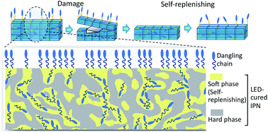
LED-cured IPN-based coatings bearing hydrophobic functional groups have been developed in order to obtain hydrophobic self-replenishing surfaces with improved mechanical properties. Acrylate/epoxide combinations have been chosen to achieve two different Tgs: a lower one to provide sufficient mobility for self-replenishing behavior and a higher one for sufficient hardness. Detailed characterizations of the mechanical and morphological properties of the IPN coatings, in the absence and presence of covalently bonded fluorinated dangling chains, have been performed. Finally, the self-replenishing behavior of these networks with intrinsic hardness has been investigated. This new approach, which is based on IPN and LED technologies could offer self-replenishing functionality for industrial applications, namely in the automotive or aerospace industry.


Introduction

Interpenetrating polymer networks (IPNs) are the combinations of two or more polymer networks, which are synthesized in the presence of one another, therefore physically entangled, but not covalently bonded. They are subject to intense current research in order to overcome the limitations of stand-alone networks and lead to novel properties with improved mechanical strength, thermal stability and chemical resistance. The glass transition temperature (Tg) of IPNs tends to be broad and covers more or less the range between its composing homopolymers. Such materials are excellent for outdoor applications acting as impact resistant materials, adhesives, aircraft, and thermosensitive, biomedical and biological materials.1–8

Photo-curing has found a large variety of applications, since this technology brings several advantages, such as being a solvent free process with low energy consumption, and rapid curing at ambient temperatures. Nowadays, this technique has already been applied to produce IPNs.9–19 The main benefit of applying a photo-curing process to produce IPNs is that the fast cross-linking reaction could kinetically impede macro-scale phase separation between the individual networks in the IPNs so that the final properties can be improved by a more controlled meso-morphology. Moreover, different polymerization mechanisms can be carried out simultaneously but independently from each other, which allow a more flexible selection of the desired chemical systems in order to tune the properties. For instance, photo-cured IPNs based on acrylate/methacrylate and epoxide combinations have gained particular attention since both radical and cationic polymerization mechanisms can be carried out simultaneously.3,11,13,17,18

In recent years, visible light sources such as LEDs are also becoming appealing, particularly for industrial applications, to carry out the photo-curing of coatings, due to their special characteristics such as long life-time, low heat generation and higher energy savings.17,20–22 Considering all these features, LED photo-cured IPNs can become a very attractive choice for the coatings field.

Low surface energy polymeric surfaces have been extensively used in industrial applications due to their advanced properties such as high hydrophobicity, easy-to-clean or anti-fouling behavior. However, these functionalities are very susceptible to damage, due to the irreversible loss of the surface functional groups upon wear in routine use. One way to address this issue is to introduce a self-healing mechanism, which has received wide interest both from academia and industry in the last decades.23–27 For polymers and polymer coatings, most reported self-healing approaches, such as encapsulation,28,29 reversible bonds/interactions30–42 or deformation recovery43,44 aim at repairing mechanical properties or material integrity. Much less attention has been paid to self-healing mechanisms aiming to recover surface functionalities. Therefore, the concept of maintaining the hydrophobic functionalities of coatings, by self-replenishing the functional groups on the damaged surfaces, is highly desired in order to extend the hydrophobic coatings service life-time.24,45 The proof-of-principle of self-replenishing hydrophobic surfaces has been reported earlier, based on model thermally cured polyester (urethane) networks.46 In the initial approach, low surface energy fluorinated dangling chains chemically bonded to the cross-linked network re-orient towards the new air/coating interfaces created upon damage.47 However, for these model systems the energy and time-consuming thermal curing process used, which is based on isocyanate chemistry, and the weak mechanical properties due to their low Tg, limit their direct industrial application. As a step towards industrially viable self-replenishing coatings, a more cost/energy effective UV-photo-curing method has been introduced for new self-replenishing coating systems consisting of PEGDA-based cross-linked networks.48 It has been shown that the coatings exhibit a clear multiple self-replenishing ability, and recover the initial chemical composition and related hydrophobicity on the damaged surface. The rate of recovery was reported to be dependent on the network properties such as Tg. Nevertheless, the mechanical properties of these new UV-cured coatings, namely hardness and scratch resistance, were still not completely satisfactory for practical use, due to the limited improvement in Tg.

As an effort to further enhance the mechanical properties of self-replenishing hydrophobic coatings, IPN-based networks combining polymers with two different Tgs were investigated. UV and LED photo-cured IPN systems have been reported17 based on acrylate/epoxide monomers with low and high Tgs respectively, to combine the flexibility of the acrylate network with the better mechanical properties of the epoxide network. The flexibility of the first is necessary to offer enough mobility for dangling chains to reorient towards the surfaces created after damage; the stronger mechanical properties of the second are required for offering better hardness reaching to industrial requirements.

In the current work, we investigate self-replenishing LED photo-cured IPN-based coatings, based on the re-orientation of low surface energy dangling chains on damaged surfaces, and the effect of the IPNs architecture on the self-recovery behavior. The final conversions of the acrylate and epoxide functionalities and the characterization of the mechanical and morphological properties of the coatings have been performed by Confocal Raman Microscopy (CRM), Dynamical Mechanical Analysis (DMA) and Atomic Force Microscopy (AFM). Thereafter, fluorinated dangling chains have been introduced into the IPNs, via covalent bonding to the acrylate network, and the self-replenishing behavior of the new hydrophobic coatings with intrinsic hardness has been investigated by using Contact Angle (CA) and X-ray Photoelectron Spectroscopy (XPS) measurements. The formation of the hydrophobic photo-cured IPN's is assessed (CRM), their meso-morphology characterized (AFM), and the influence of the acrylate/epoxide ratio on the self-replenishing ability (CA, XPS) established.

Experimental section

Materials

Polyethyleneglycol 600 diacrylate (Sartomer SR 610, viscosity = 80 mPa s−1 at 25 °C) was chosen for its flexibility and low Tg. (3,4-Epoxycyclohexane) methyl 3,4-epoxycyclohexylcarboxylate (Dow Chemical, UVR 6110, viscosity = 220–250 mPa s−1 at 25 °C) was selected for its high reactivity and good mechanical properties. A combination of isopropyl-9H-thioxanthen-9-one (ITX)/benzyl alcohol (BA)/iodonium salt, ((4-methylphenyl)[4-(2-methylpropyl)phenyl], hexafluorophosphate, Irgacure-250) was used as LED curable photoinitiating system. ITX and BA were obtained from Sigma-Aldrich and Irgacure 250, diluted in propylene carbonate (25 wt%), was obtained from BASF. 1,4-Dioxane has been purchased from Sigma Aldrich. All these compounds were used without any further purification. The synthesis and characterization of the fluorinated-polymeric dangling chains (Rf8-PCL16-MA), which consist of a 8-carbon fluorinated low-surface-energy group (Rf8), a linear polycaprolactone (PCL) based spacer, terminated with a methacrylate (MA) group, have been described previously.48,49 The degree of polymerization of the PCL spacer is 16, corresponding to number average molecular weight of 1827 Da for the PCL spacer only.

Selection and preparation of photo-curable formulations

Photo-curable formulations were prepared by mixing the acrylate (SR 610) and epoxide (UVR 6110) resins at different weight ratios (wt%). The photoinitiating system, which has been reported previously17 is composed of ITX, Irgacure 250 and BA and was added to the formulation. The fluorinated dangling chains (DCs) with a poly(caprolactone) spacer were introduced at a constant amount in the IPNs for bringing the self-replenishing effect. 1,4-Dioxane was used to improve the miscibility between the acrylate and the DCs, to avoid any segregation before LED-curing. In this work, the different IPNs will be described as xAyE, A standing for the radical system introduced at x wt%, and E corresponding to the cationic system introduced at y wt%. Table 1 shows the composition of the different formulations. Diverse acrylate/epoxide ratios have been investigated (70A30E, 60A40E, 50A50E and 40A60E). A self-replenishing study was carried out after the introduction of 1 wt% of fluorine regarding the total formulation (70A30E 1F, 60A40E 1F, 50A50E 1F and 40A60E 1F). For the coatings characterization (CRM, DMA and AFM), homogeneous formulations were prepared by mixing all ingredients overnight and the final photo-curable mixtures were applied onto polypropylene substrates with a 40 μm coating bar. The formulations were cured under LED by using a 395 nm Firejet FJ200 LED from Phoseon (12 W cm−2) connected to a belt conveyor at a speed of 10 m min−1. The light intensity was 550 mW cm−2 (UVA: 30 mW cm−2, UVV: 520 mW cm−2). All coatings were tack-free after 10 passes and a light exposure of 5 s. In the case of 70A30E 1F, a slight haziness was observed while all other films were transparent. For preparing films for the self-replenishing study, a 395 nm Integration Technology LED source with light intensity of 600 mW cm−2 (UVA: 80 mW cm−2 and UVV: 520 mW cm−2) has been used for the curing process. The coatings were irradiated for 120 seconds, after which they appeared as transparent and tack-free films, except for 70A30E 1F which also showed a slight haziness.
Table 1 Composition of the formulations. ([ITX] = 2 wt%, [BA] = 4 wt%, [Irgacure 250] = 3 wt% were added as photoinitiating system)a
Sample name Fluorine amount with respect to total formulation (wt%) Fluorine amount with respect to acrylate (wt%) Acrylate SR 610 (wt%) Fluorinated dangling chains (wt%) Epoxide UVR 6110 (wt%) Photoinitiating system (wt%) Dioxane (wt% with respect to total acrylate part)
a Mixtures are described as xAyE, A standing for the radical system introduced at x wt%, and E corresponding to the cationic polymer introduced at y wt%. Dioxane has been introduced at 25 wt% with respect to the acrylate part.
70 A30E 0 0 66 0 25 9 0
70 A30E 1F 1 1.52 58.9 7.1 25 9 25
60 A40E 0 0 56 0 35 9 0
60 A40E 1F 1 1.78 48.9 7.1 35 9 25
50 A50E 0 0 46 0 45 9 0
50 A50E 1F 1 2.17 38.9 7.1 45 9 25
40 A60E 0 0 36 0 55 9 0
40 A60E 1F 1 2.77 28.9 7.1 55 9 25


A distinct characteristic of epoxide polymerization is that the propagating oxonium ions do not react among themselves, thus limiting termination reactions and allowing the polymerization to further proceed in the dark. In consequence, all the coatings prepared were kept inside a desiccator at least for 3 days, before further characterizations.

Techniques

Confocal Raman Microscopy (CRM). Confocal Raman Microscopy (CRM) was used to determine the final conversion of the acrylate and epoxide functionalities of the IPN networks. The measurements were performed on a Via Reflex Raman microscope from Renishaw, which couples a Raman spectrophotometer with a Leica DM2500 microscope. The excitation wavelength was provided by a helium–neon laser emitting at 632.6 nm. 30 s of accumulation were needed at each step to obtain reasonable signal to noise ratio in the deeper layers. A circular polarization of the laser beam was achieved by placing a λ/4 wave plate on the optical path of the incident light to get rid of polarization effects. A 600 L mm−1 grating optimized for the visible light and providing a spectral window of 1950 cm−1 was used to disperse the light on a CCD NIR deep depletion Peltier-cooled detector camera. The confocal mode was defined by the spectrophotometer entrance slit opened to 20 μm in the back focal plane of the objective lens and a selection of 3 pixels perpendicular to the slit axis on the CCD camera. The spectral resolution given by the combination slit/CCD/grating was 8.7 cm−1. The dry objective used was N PLAN 50× Leica with a numerical aperture of 0.75. Oil objectives are commonly used to minimize possible refraction effects and have access to a trustworthy nominal depth.21 However, dry objective was chosen simply in this study to calculate the final average conversion values of acrylate and epoxide functionalities.

LED-cured films were prepared as described in the previous section. The decrease of the vibrational bands of the functional groups of each monomer was followed by CRM. The area of the band attributed to the stretching vibration of the C[double bond, length as m-dash]C groups at 1636 cm−1 (AνC[double bond, length as m-dash]C) was followed as a function of depth for the acrylate, and the band attributed to the deformation vibration of the oxirane ring at 785 cm−1 for the epoxide. In order to avoid data misinterpretation due to the loss in intensity with increasing depth, fluctuations of the laser intensity, or other external perturbations, the area of the band attributed to the stretching vibration of the carbonyl groups of the acrylate and epoxide monomers (AνC[double bond, length as m-dash]O) at 1721 cm−1, which was not affected by curing, was chosen to normalize the νC[double bond, length as m-dash]C band for all formulations. The conversion was then calculated using eqn (1),

 
image file: c6ra03758e-t1.tif(1)
where Az corresponds to the absorbance ratio (AνC[double bond, length as m-dash]C/AνC[double bond, length as m-dash]O)z of the vibration bands of the functional groups in the cured films, while Am = (AνC[double bond, length as m-dash]C/AνC[double bond, length as m-dash]O)m is the absorbance ratio determined from the liquid formulation. The measurements were started a few microns below the surface of the cured film to obtain spectra without any noise due to an air contact, and the films were scanned for every 3 microns through the depth (10 spectra were taken in total). No difference in conversion was observed through the depth for both acrylate and epoxide polymerization. The average of these values is reported as the final conversion.

Dynamical mechanical analysis (DMA). Dynamic mechanical analysis (DMA Q800 from TA instruments) was used to characterize the viscoelastic properties of the IPN films in tensile mode at a frequency of 1 Hz. DMA has been performed on LED-cured films (11 × 5.4 × 0.05–0.07 mm3 rectangular samples) to determine the storage modulus (E′) representing the elastic behavior of the materials and the loss factor (tan[thin space (1/6-em)]δ) defined as the ratio between the loss modulus and the storage modulus. tan[thin space (1/6-em)]δ curves were obtained as a function of temperature at a constant heating rate of 3 °C min−1. In the glass transition temperature region, a strong decrease of E′ can be observed, whereas tan[thin space (1/6-em)]δ reaches a maximum that corresponds to the Tg of the photo-cured films.50
Atomic force microscopy (AFM). Morphology investigations were performed by atomic force microscopy (AFM) on the top air-interfaces of the LED-cured films, using an AFM apparatus from NT-MDT (Ntegra Spectra). A NSG 01 tip (silicon, nominal resonance of 150 kHz, nominal spring constant of 5.1 N m−1) was used for acquiring images in semi-contact mode.

For a more precise investigation of the different systems, the root mean square (RMS) roughness, defined as the RMS average of the height deviations from the mean value (eqn (2)), was calculated for the coatings without dangling chains.

 
image file: c6ra03758e-t2.tif(2)
where x is the height or phase difference between a given data point and the corresponding data point for the average plane, and n is the total of the measured points.

This RMS was obtained from AFM topography images using the roughness analysis tool of Nova software from NT-MDT, applied on the whole scanning area. In the same manner, phase RMS values have been estimated from phase images obtained in AFM tapping mode.

Solvent extraction. The amount of coating components not covalently bonded to the networks in the LED-cured films was evaluated by solvent extraction experiments. The films were first vacuum dried in the oven at +40 °C to remove the absorbed moisture until their mass remained constant. Then, the films were immersed in chloroform (in which all the components are soluble) for 30 minutes, followed by sonication in a sonication bath for 15 minutes. After the LED-cured films and solvents were separated, the solvent was evaporated under vacuum to collect the solid extractable residue. The solid residue was then vacuum dried in oven at +40 °C for 24 hours and +60 °C for 4 hours. The weight loss corresponding to the extraction of the non-bonded species was calculated using eqn (3),
 
image file: c6ra03758e-t3.tif(3)
where Moriginal and Mextractable represent the mass of the original films and the mass of the extractable residues, respectively.
Contact angle (CA) measurements. The hydrophobicity of the films was evaluated by dynamic water contact angles (CA) measured with a Data Physics OCA 30 instrument. Advancing (CAadv) and receding (CArec) water contact angles were measured in the ARCA-software mode, with the following procedure: a 0.2 μL droplet was firstly placed on the surface; further water was injected into the droplet up to 15 μL at the speed of 0.5 μL s−1; after a waiting period of 2 seconds, the water was retracted from the droplet until 2 μL at 0.5 μL s−1. The CAadv was calculated when the water droplet/coating interface migrated outwards, while the CArec was calculated when such interface moving inwards. The errors provided correspond to the standard deviation of the average of at least three measurements on different surface regions.
X-ray photoelectron spectroscopy (XPS). The chemical composition of the top-surface of the LED-cured films was investigated by X-ray photoelectron spectroscopy (XPS), carried out with a K-Alpha, Thermo Scientific spectrometer using an aluminium anode (Al Kα = 1486.3 eV) and operating at 510 W with a background pressure of 8 × 10⁻⁸ mbar. The spectra were recorded using the VGX900 data system and collecting an average of 30 scans for each measurement. The spectra were acquired at take-off angle of 0° relative to the surface normal, corresponding to a probe depth of about 10 nm. The errors provided correspond to the standard deviation of the average of four measurements on different surface regions. The fluorine/carbon (F/C) atomic ratio was determined from curves fitted to the C 1s spectra, according to different carbon environments (C–C, C–H, C–O, C–N, C[double bond, length as m-dash]O, C–F2 and C–F3), and F 1s spectra. The areas were corrected for the element sensitivity and the F/C atomic ratio was estimated from the area ratio by eqn (4),
 
image file: c6ra03758e-t4.tif(4)
where A and S represent the peak area and element sensitivity, respectively. The extent of fluorine surface segregation was evaluated by the fluorine enrichment factor calculated with eqn (5) and the self-replenishing efficiency (for the recovery of the surface chemical composition) was assessed by the XPS results, according to eqn (6).
 
image file: c6ra03758e-t5.tif(5)
 
image file: c6ra03758e-t6.tif(6)
Microtoming. The self-replenishing ability of the LED-cured films was investigated by applying an intentional surface damage, through controlled microtoming of thin slices (up to a few tens of μm) parallel to the original surface of the polymer films. The intended damage was carried out at room temperature by microtoming with a Leica RM2165 Microtome. A home-made design sample holder and an epoxide sacrificial layer, previously reported,46 were used to ensure the removal of surface layers plane-parallel to the films surface and with a minimal introduction of artifacts at the surface, which could affect the post-damage characterization. The surface arithmetic roughness (Ra, eqn (7)) obtained with confocal optical microscopy (μSurf, NanoFocus) on the films before and after the microtoming was used to analyze the additional roughness possibly introduced by the cutting procedure. For each surface, the roughness value reported is the average of at least five measured arithmetic roughness, with the deviation associated with the average of the standard deviations from each measurement.
 
image file: c6ra03758e-t7.tif(7)
where xi is the height difference between a given data point and the corresponding data point for the average plane, and n is the total of the measured points in one scan.
1H NMR. The chemical structure of the synthesized dangling chains was characterized by 1H NMR, carried out on a Varian 400 spectrometer at 25 °C operating at 400 MHz. Deuterated chloroform (with TMS as internal standard) was used as solvent.
MALDI-ToF. In order to analyze the chemical structure of the extractable residues, matrix-assisted laser desorption/ionization time-of-flight mass spectrometry (MALDI-ToF MS) measurements were performed on a Voyager-DE Pro instrument (Perspective Biosystems, Framingham, MA). The polymers were dissolved in THF and potassium trifluoroacetate was used as the ionizing agent. The end group of the polymer was analyzed by fitting the molecular weight, associated with m/z values, to the expected chemical structure.

Results and discussion

Neat IPN and DC-IPN films characterization

Final conversions determined by CRM. The LED-cured films have been firstly investigated in terms of conversion of the reactive functional groups. RTFTIR spectroscopy is typically used to determine conversion kinetics and final conversions in light cured films. However, for the selected oligomers, there was an overlap of the vibrational bands specific to the reactive functions. Therefore, CRM was used to evaluate the conversion of both acrylate and epoxide functions in the IPN networks, without and with hydrophobic dangling chains. The results are summarized in Table 2.
Table 2 Conversion values of LED-cured IPNs obtained by CRM for different acrylate/epoxide ratios. LED exposure at 395 nm (light intensity: 550 mW cm−2 and total exposure time: 5 s)
Formulations Acrylate conversion (%) Epoxide conversion (%) Epoxide conversion after 3 days (post-curing at RT) (%)
a This sample was tacky after light exposure and has not been characterized by CRM.
100A0E Not measured (tacky film)a
70A30E 89 75 78
60A40E 88 73 76
50A50E 95 74 77
40A60E 95 80 80
0A100E 59 Not measured
70A30E-1F 86 72 76
60A40E-1F 88 74 76
50A50E-1F 95 78 78
40A60E-1F 95 78 80


Epoxide conversion is about 72–80% for all the films. The vitrification of the epoxide network limits the conversion of epoxide functional groups. However, the acrylates present in the network act as a plasticizer to some extent, since the conversion of the neat epoxide levelled off at 59% for the same experimental conditions.17 Post-polymerization of the remaining epoxide functions was limited even after 3 days dark storage. For the acrylate polymerization, the conversion was 95% for 50A50E and 40A60E, but slightly decreased for higher acrylate ratios (70A30E and 60A40E). The epoxide content in the IPNs, which acts as barrier to the atmospheric oxygen due to an increased viscosity, may explain the variable acrylate conversions. In addition, photosensitizing iodonium salts with benzyl alcohol leads to an efficient generation of reactive cations. As a consequence, epoxide ring opening becomes faster than acrylate polymerization and thus limits the double conversion in a vitrified system. The addition of DC to IPNs did not have any influence on the final conversions.

Mechanical properties: DMA. DMA is an efficient technique to analyze the degree of interpenetration of IPNs. The Tg values of cross-linked polymers can be detected from the maximum of the tan[thin space (1/6-em)]δ curves (Fig. 1). A narrow peak of tan[thin space (1/6-em)]δ can be explained by a high degree of interpenetration between the two networks, while two clearly separated glass transition peaks for each homopolymers indicate phase separation. An intermediate degree of mixing in IPNs is represented by a single broad transition.17,18,51,52
image file: c6ra03758e-f1.tif
Fig. 1 tan[thin space (1/6-em)]δ curves of LED-cured films with different acrylate/epoxide ratios without and with dangling chains.

It can be noticed from Fig. 1 that no separate epoxide or/and acrylate homopolymer phases could be identified (Tg of UV-cured acrylate and epoxide homopolymers are −30 °C and 175 °C, respectively). Some degree of interpenetration was achieved and co-continuous phases are observed between both networks, independently of acrylate/epoxide ratio. The determination of the acrylate/epoxide ratios for the co-continuous phases is given in Table S1 by applying the Fox equation (eqn (S1)). A single peak at −10 °C with a slight shoulder at higher temperature was obtained for 70A30E. This shoulder can be attributed to another IPN interpenetrated and entangled with dominating acrylate-rich one. When the epoxide content increases up to 40 wt% in IPN (60A40E), DMA shows maximum at higher temperature (Tg at 7 °C). A shoulder is becoming more distinctive, which is an indication of the change of acrylate/epoxide ratios in the IPNs. Further epoxide increase (50A50E and 40A60E) leads to higher Tgs, and the different IPNs containing different ratios of acrylate and epoxide become epoxide-richer (Fig. 1, Table 4). When DCs are introduced into IPNs, similar Tg values were obtained without significant change in the shape of the curves (Fig. 1). The increase of the height of the tan[thin space (1/6-em)]δ curve, observed in most cases (except for 60A40E 1F) can be explained by the loss of rigidity, possibly due to the presence of crystalline domains from the polymeric spacer, as will be discussed later on. Indeed, when the polymer gains more flexibility and becomes less rigid, there is a decrease of the storage modulus (E′) or increase in loss modulus (E′′) leading to lower stiffness (Table S1).

Evaluation of the amount of extractables: solvent extraction. In order to evaluate the amount of unreacted or non-network-incorporated components (i.e., extractables), solvent extraction experiments were performed. All the LED-cured films showed less than 5 wt% of extractables in relation to the overall solid content of the films (Table 3), but the higher values were obtained for the films with more acrylate in the system.
Table 3 Extractable residues weight percentage (%) in relation to the overall solid content in the films (deviation within 0.5 wt%)
Solid extract (wt%) 40A60E 50A50E 60A40E 70A30E
Neat IPN 3.1 3.7 4.9 5.0
DC-IPN 2.5 3.7 4.2 5.5


Before the chemical characterization on the prepared films, the solvent dioxane in the initial formulation is confirmed to have been evaporated completely by thermogravimetric analysis. In spite of the relatively low amount of extractable residues, they were characterized via 1H-NMR and Maldi-ToF spectroscopy to identify the chemical species present and their chemical composition. The 1H-NMR spectra of the extracts were compared with the reference spectra of each pure component used in the formulations to identify the main chemical species present (Fig. 2).


image file: c6ra03758e-f2.tif
Fig. 2 1H-NMR spectra of the solid residues extracted from LED-cured 40A60E 1F, 50A50E 1F, 60A40E 1F and 70A30E 1F films. The chemical shifts ranges labeled with numbers correspond to: (1) ITX, (2) BA, (3) PCL block in the dangling chains, (4) UVR 6110 (epoxide) and (5) SR 610 (PEGDA).

First, chemical shifts attributed to the ITX and benzyl alcohol molecules from the photoinitiating system have been identified in the residues (Fig. 2, peaks labeled with #1 and #2, respectively). In the photoinitiation process, ITX acts as photo-sensitizer and is not covalently bonded to the network; it is therefore logical to observe its presence in the extracts. Benzyl alcohol, hydrogen donor for the generation of aryl radicals, is oxidized by iodonium salt to generate reactive cation species.17 Its deprotonation yields benzaldehydes and protonic acid,53 and explains the existence of non-bonded benzaldehyde moieties observed in the extractables. Second, chemical shifts attributed to the UVR 6110 (epoxide) and SR 610 (PEGDA) monomers were also identified (Fig. 2, peaks labeled with #4 and #5, respectively). These components are probably due to the uncomplete conversion of the radical and cationic polymerizations (Table 2), or the formation of small amounts of free-oligomers which were not bonded to the networks. Finally, chemical shifts attributed to the PCL block of the DC (Fig. 2, peaks labeled with #3), indicated the existence of non-bonded DC in the extracts. To clarify the presence of the DC in the extractables, a polymer end-groups analysis was carried out by Maldi-ToF (see Fig. S1 for details).

The analyses of the spectra indicated that the DC residues were in fact consisting of a small amount of hydroxyl-terminated DCs, from the initial materials used. These residues could be originating from the synthesis of the methacrylate-terminated DC,48 fully described in our previous works, or from the hydrolysis of ester bonds in the DC along the curing and extraction processes. Expectedly, the OH-terminated DC could not be incorporated by the polymerization methods used here, and thus remain as free and extractable residues. Most importantly, no methacrylate-terminated DCs were identified, indicating their successful incorporation via chemical bonding into the acrylate/epoxide networks by LED-curing. Regrettably, from these analyses it was not possible to discriminate exactly in which phase(s) the MA-terminated DC were incorporated.

Surface characterization: AFM. The surface morphology of neat IPN and DC-IPN films was investigated by AFM in tapping mode. The neat 70A30E and 40A60E films did not show distinguishable phase domains at the air–films interface, within the length scales imaged. These results confirm the co-existence of hard and soft phases resulting from the strong interpenetration of IPNs of different compositions (Fig. 3).
image file: c6ra03758e-f3.tif
Fig. 3 AFM height and phase images (1 × 1 μm2) of the 70A30E and 40A60E coatings.

Interestingly, for all the DC-IPN films, crystal-like morphologies were observed by AFM (Fig. 4) when imaging the top air-interfaces. However, in the crystal-free areas, a good IPN interpenetration was still observed as reported in Fig. S2. Crystal-like morphologies were mainly attributed to the crystallization of the PCL-spacer of the methacrylate-terminated DC, and possibly also to the residual amounts of the hydroxyl-terminated DC, as explained in the previous section. Crystallization investigations have been performed for the DC-IPN films by DSC and Wide-Angle X-ray Diffraction (WAXD). The melting transition and diffraction peaks have been observed at ∼43 °C (Fig. S3A) and 2θ = 21.2°, 21.7° and 23.4°(Fig. S3B), which are close to the values reported in the literature54 for PCL-based materials for these experimental conditions, confirmed the presence of crystalline PCL.


image file: c6ra03758e-f4.tif
Fig. 4 AFM height and phase images (50 × 50 μm2) of 70A30E 1F and 40A60E 1F coatings.

The crystallinity was more pronounced for the 70 A30E 1F film (Fig. 4), which shows a surface mostly covered by leaves-like patterns of various sizes, possibly due to the easier crystallization (i.e., higher mobility) of the PCL-block in a film with lower Tgs. This explains also the slight haziness observed in the DC-IPN films, particularly pronounced a few days after the curing. For 40 A60E 1F, crystallization occurred to a lower extent. Randomly distributed leaves-like patterns of various sizes can be seen in Fig. 4. In addition, film microtoming was done to investigate by AFM the crystal-like structure distribution along the thickness, but the images obtained were inconclusive due to surface damage. However, AFM measurements carried out at the surface of the films in contact with the polypropylene substrate do not show crystal-like structure (Fig. S4). This result argues for self-segregation of the fluorinated-DC towards the air-coating interface and will be confirmed in the following section.

Self-replenishing study

Initial surface properties. The surface hydrophobicity of the LED-cured films was evaluated by dynamic water contact angle measurements. All the reference films without DC showed a hydrophilic character with CAadv around 40° and low CArec (Table 4). When the DCs were incorporated, the films clearly exhibited a pronounced improvement in both CAadv and CArec. These results indicate a strong surface enrichment at the air-coating interface with the low surface energy groups of the DC. This surface enrichment was confirmed by the fluorine–carbon (F/C) atomic ratio estimated from XPS measurements. Theoretically, if the DCs were distributed throughout the depth of the films homogeneously, the F/C atomic ratio at the surface should be the same to the theoretical bulk average value (0.011, Table 4). In fact, all DC-IPN LED-cured films prepared displayed a much higher F/C atomic ratio, indicating surface enrichment factors of 16–37, which results in a significant increase in surface hydrophobicity. It should be noted that in comparison to the neat IPN films, an increase in surface roughness due to the crystalline domains introduced by the presence of the DCs, as shown by the AFM characterization, may have also contribute to the increase in CA. Nevertheless, the much higher F/C ratios estimated at the surface of the DC-IPN films clearly account for the increased hydrophobicity.
Table 4 Hydrophobicity of the LED-cured polymer films shown by dynamic water contact angles and surface fluorine-concentration demonstrated by XPS on the initial surfaces
Sample CAadv (°) CArec (°) F/C ratio bulk avg. F/C ratio initial Surface enrichment factor Tg (°C)
40A60E 39 ± 3 21 ± 2 79
50A50E 37 ± 2 19 ± 2 24; 68
60A40E 39 ± 3 15 ± 3 7
70A30E 41 ± 1 13 ± 3 −10
40A60E 1F 102 ± 3 50 ± 5 0.011 0.18 ± 0.04 16 75
50A50E 1F 112 ± 1 66 ± 2 0.011 0.33 ± 0.03 30 30; 57
60A40E 1F 117 ± 2 73 ± 3 0.011 0.41 ± 0.03 37 0
70A30E 1F 116 ± 2 80 ± 5 0.011 0.41 ± 0.02 37 −11


Self-replenishing behavior. In the previous papers, self-replenishing properties have been demonstrated for several chemical systems differing in the network-building units and curing methods. As a proof-of-principle, initially, a thermally-cured polyurethane cross-linked network was used as model system to demonstrate the self-replenishing behavior, by the spontaneous self-orientation of the incorporated low surface energy DCs towards the new interfaces created upon damage.47 In a follow-up, polymer films prepared via the UV-curing of PEG diacrylate-based cross-linked networks also demonstrated a clear multiple self-replenishing ability, even though the cross-linking occurred much faster as compared to the thermally-cured system.48 In this case, self-replenishing was demonstrated to occur at a lower rate, e.g. a few days for complete recovery, when the Tg of the network increased. The gradually-enhanced hydrophobicity and F/C atomic ratio observed in time for such systems with higher Tg, also confirmed the self-replenishing mechanism via the re-orientation of the dangling chains. As discussed in the previous section, the thermomechanical properties of the current IPN LED-cured films with different acrylate/epoxide ratios proved to be different. Therefore, different kinetics of self-replenishing are also expected for these LED-cured films.

All the films were intentionally damaged by sequentially removing top layers with a thickness of ∼20 μm per cut with a microtome, parallel to the air-coating interface. In view of the range of Tgs of the LED-cured films, the microtoming was performed at room temperature for all the films to avoid the introduction of significant roughness. The roughness changes were evaluated by analyzing the film surfaces with confocal optical microscopy, before damaging, on the 1st and 10th day after damaging, and after an annealing step at 50 °C for 2 hours (Table 5).

Table 5 The roughness measured by confocal optical microscopy over an area of 800 μm × 800 μm before and after damage and after an annealing step at 50 °C
Sample Arithmetic roughness (nm)
Initial 1 day after damage 10 days after damage Annealed
40A60E 1F 25 ± 3 152 ± 28 165 ± 41 152 ± 37
50A50E 1F 41 ± 5 35 ± 6 29 ± 9 31 ± 8
60A40E 1F 22 ± 5 38 ± 5 27 ± 6 21 ± 5
70A30E 1F 32 ± 5 29 ± 6 57 ± 5 62 ± 9


For all the films the roughness increment after microtoming at room temperature was limited, with the exception of 40A60E 1F. This may be attributed to a larger cutting resistance caused by the higher Tg of this film (Table 4). After 10 days recovery, only 70A30E 1F showed a slightly increased roughness, most likely due to the crystallization of the PCL block in the ‘softer’ (lower Tg) network, as discussed before. Generally, the annealing step did not change significantly the surface roughness.

To investigate the hydrophobicity recovery after damage, water contact angle measurements (CAadv) were performed from the earliest possible practical time after the damage (∼4 h), till 10 days after the damage. Afterwards, the damaged surfaces were annealed at 50 °C for 2 hours, to make sure that the recovery process was complete (Fig. 5). Within a short time after damage (∼4 h), the 70A30E 1F and the 60A40E 1F films exhibited a CAadv similar or even slightly higher than the CA measured on the original surface (day “zero”). 60A40E 1F, however, shows a much more pronounced initial decrease of the CAadv upon damaging, from 116° down to 94°.


image file: c6ra03758e-f5.tif
Fig. 5 The hydrophobicity recovery after damaging measured at varied times by water CAadv (open symbols). The solid points at day 0 indicate the CAadv values of the initial surface (before damage) and those at 11 days indicate the values after annealing.

Under the same conditions, the two other films (50A50E 1F and 40A60E 1F) showed an initial pronounced drop in CAadv after the damaging event, even down to the hydrophilic range (∼60°), and also a very slow recovery after ∼4 hours. Upon longer times of recovery, both films slowly recover their hydrophobicity from ∼60° (4 hours after damage) to ∼68°, and their CAadv was finally stabilized after 10 days of recovery at 86° and 80°, respectively. After 10 days of self-recovery, all the films were annealed and their CAadv were measured, confirming that the films reached their recovery equilibrated values. However, the CAadv of 50A50E 1F and 40A60E 1F did not reach the level of their original surfaces.

Based on the results above, we can conclude that all the coatings exhibit a clear ability to self-replenishing and recover their hydrophobicity, but in different speeds and extents to recovery.

The fluorine concentration on the damaged surfaces was examined by XPS, after 2 and 10 days of recovery, by analyzing the polymer layers removed sequentially at different cutting depths. For all the films and at all cutting depths, the F/C atomic ratio was clearly higher than the “theoretical bulk average” (Table 4 and dashed line in Fig. 6), which supports the idea that the recovery of hydrophobicity is due to the surface-segregation of the fluorinated low surface energy DCs. Besides, the F/C ratio measured after 2 and 10 days of recovery showed no significant difference, indicating that the surface-segregation by re-orientation of the DC could reach its equilibrium within 2 days for all the films.


image file: c6ra03758e-f6.tif
Fig. 6 Fluorine/carbon (F/C) atomic ratio measured by XPS for the LED-cured films, on slices obtained at different depths, after 2 days of recovery (assessed upon microtoming of layers parallel to the air-polymer interface). Cutting depth = 0 μm corresponds to the original, non-damaged surfaces. The dashed line corresponds to the “theoretical bulk value” expected, if the DCs were homogenously distributed throughout the “bulk” of the polymer film, i.e., no surface segregation.

In terms of recovery of the fluorine-content at the surface, for 70A30E 1F and 60A40E 1F the F/C ratio measured for deeper cutting depths were maintained, within the error margins, at a level very similar to those of the respective original surfaces (Fig. 6 and Table 6). These results are in agreement with the fact that the CAadv of these two films were fully recovered within 2 days (Fig. 5). However, for 50A50E 1F and 40A60E 1F, it was clear that at deeper cutting depths, the measured F/C ratios were generally lower than their initial levels (Fig. 6), even after 10 days of recovery (Table 6). Accordingly, the CAadv of the 50A50E 1F and 40A60E 1F surfaces were never fully recovered, even after annealing. Hence, the recovery of the surface fluorine enrichment fully supports the results obtained for recovery of the films hydrophobicity, indirectly given by the water CA measurements.

Table 6 The F/C atomic ratio of DC-IPN LED-cured films, measured on the initial surface, 2 days and 10 days after damage by XPS
Sample F/C atomic ratio
Initial surface Damaged surface (60 μm) 2 days of recovery Damaged surface (60 μm) 10 days of recovery
40 A60E 1F 0.18 ± 0.04 0.10 ± 0.01 0.10 ± 0.02
50 A50E 1F 0.33 ± 0.03 0.21 ± 0.03 0.22 ± 0.01
60 A40E 1F 0.41 ± 0.03 0.35 ± 0.03 0.36 ± 0.03
70 A30E 1F 0.41 ± 0.02 0.39 ± 0.02 0.41 ± 0.03


Acrylate/epoxide ratio effect on self-replenishing behavior. Considering the results discussed above, the self-replenishing ability of the IPN LED-cured films could be clearly demonstrated, in spite of the use of acrylate/epoxide based IPNs cured by LED irradiation, which have higher Tgs than the previously reported self-replenishing films.47,48 Furthermore, the self-replenishing ability can be clearly tuned by adjusting the soft-acrylate/hard-epoxide ratio of the films.

On the original surface after film formation by LED-curing, the hydrophobicity and the fluorine surface enrichment increased with an increasing amount of acrylate on the films (Table 4). This can be explained by the difference in the network rigidity, which is also manifested by the Tgs measured by DMA (Table 4). With less network rigidity, the chemically-bonded low surface energy DCs can more easily self-orient towards the air-interface upon film formation, leading to a higher F-surface enrichment and thus a more hydrophobic surface.

When inflicting damage on the surfaces of the films, the time-periods involved in the surface hydrophobicity recovery were also clearly correlated with the acrylate/epoxide ratio. Films dominated by the “softer” network phase (more acrylate) reached their hydrophobicity equilibrium faster. The film 70A30E 1F with the highest acrylate weight percentage amongst the investigated ones (Table 1), recovers its hydrophobicity to the maximum within only 4 hours after damaging, while the films with more “rigid” network phases (i.e., less acrylate) need much longer time to increase their surface hydrophobicity (around 18 hours for 60A40E 1F and 2 days or even longer for 50A50E 1F and 40A60E 1F, respectively) (Fig. 6 and Table 6). This difference in the increase or recovery kinetics is believed to be due to a restricted mobility in the overall systems, as a consequence of the increase in Tg upon reduction of the acrylate part.

Another significant effect was observed in the self-replenishing efficiency for the recovery of the surface chemical composition (Table 7), which can be calculated from the equilibrated F/C ratio measured on the recovered surfaces, after damage (eqn (6)).

Table 7 Self-replenishing efficiency (calculated with eqn (6)) for the recovery of the surface chemical composition, based on the F/C ratio measured by XPS (calculated with eqn (4))
  40A60E 1F 50A50E 1F 60A40E 1F 70A30E 1F
Self-replenishing efficiency 56% 70% 90% 97%


For the ‘softer’ systems (70A30E 1F and 60A40E 1F), the self-replenishing efficiency was above 90%, while for the “harder” systems, it did not reach values higher than 70%. A possible explanation could be related to the distribution of the low surface energy DCs in the IPN systems. The solvent extraction results proved that nearly all the methacrylate-terminated dangling chains are chemically bonded to the films (Section 3.1.3), and it is very probable that they preferentially bond to the acrylate-network due to the methacrylate/acrylate copolymerization rates. Since the DMA characterization indicated the existence of two tan[thin space (1/6-em)]δ peaks or a very broad peak for all the films (Fig. 1 and Table 3), some phase separation could be expected, even though the AFM indicated a homogeneous morphology within the limitations of the length scale imaged. Hence, we can not exclude a possible phase separation at a very small scale, i.e., below the resolution of currently applied AFM method, typically ∼20 nm. Therefore, the fluorinated DCs could be located either in the acrylate domains or entangled near the acrylate/epoxide interfaces. On the one hand, the former case could explain the results we observed for the self-reorientation of the DCs on films with higher acrylate amount. On the other hand, in the latter case the DCs would be “geographically” locked by the glassy epoxide networks, where only short segments (e.g. of only a few atoms) would be mobile. Consequently, with more epoxide on the IPN films, the amount of DCs restricted near the acrylate/epoxide interfaces would be higher. This could explain why with more epoxide, the self-replenishing efficiency at the equilibrium state showed a consistent drop (Fig. 6 and Table 6).

Conclusions

IPNs based on acrylate/epoxide combinations were prepared in the absence and presence of fluorinated dangling chains (DCs), which are covalently bonded to the network, in order to achieve self-replenishing LED-cured coatings, with improved mechanical properties, i.e., with a glass transition temperature above room temperature. Tack-free IPN-based films have been achieved under LED irradiation for different acrylate/epoxide ratios. The investigation of the mechanical properties showed that the Tgs increase with higher epoxide content and that the addition of the DCs to the formulation did not have a significant influence on the Tg of the networks. Morphology investigations indicated that the neat IPN networks have a homogeneous morphology, within the length scale probed, and that the DC-IPN films show the presence of crystalline domains, attributed to the polycaprolactone (PCL)-spacers of DC.

All the studied films showed efficient self-replenishing ability, although at different rates and to a variable extent. With an increasing acrylate (soft component) content, the fluorine content on the initial surface increases, due to the easier self-reorientation of the chemically-bonded fluorinated DC, thereby increasing the self-replenishing ability. Similarly, the recovery ability and recovery rate increased with a higher acrylate content in the IPN films.

In conclusion, thermomechanically-improved hydrophobic self-replenishing coatings could be achieved by using LED-curing and IPN-based networks. Tuning the chemical composition of the IPN networks allows enhancing the self-replenishing ability of the films and opens new horizons for the coating industry.

Acknowledgements

This research forms part of the research programme of the Dutch Polymer Institute (DPI), project #758 (SER-LED).

Notes and references

  1. L. Sperling, in Interpenetrating polymer networks, ed. D. Kelmpner, L. H. Sperling and L. A. Utracki, American Chemical Society, Washington, 1994, pp. 3–38 Search PubMed.
  2. A. P. Mathew, in Advances in Elastomer I, Advanced Structural Materials, ed. P. M. Visakh, S. Thomas, A. K. Chandra and A. P. Mathew, Springer Berlin Heidelberg, Berlin, Heidelberg, 2013, vol. 11, pp. 283–301 Search PubMed.
  3. L. H. Sperling and V. Mishra, Polym. Adv. Technol., 1996, 7, 197–208 CrossRef CAS.
  4. Z. Y. Fu, C. L. He, H. B. Li, C. Yan, L. M. Chen, J. H. Huang and Y. N. Liu, Chem. Eng. J., 2015, 279, 250–257 CrossRef CAS.
  5. H. B. Li, Z. Y. Fu, C. Yan, J. H. Huang, Y. N. Liu and S. I. Kirin, J. Colloid Interface Sci., 2016, 463, 61–68 CrossRef CAS PubMed.
  6. H. B. Li, Z. Y. Fu, L. Yang, C. Yan, L. M. Chen, J. H. Huang and Y. N. Liu, RSC Adv., 2015, 5, 26616–26624 RSC.
  7. S. Murayama, S. Kuroda and Z. J. Osawa, Polymer, 1993, 34, 2845–2852 CrossRef CAS.
  8. M. Tsumura, K. Ando, J. Kotani, M. Hiraishi and T. Iwahara, Macromolecules, 1998, 31, 2716–2723 CrossRef CAS.
  9. M. de Brito, X. Allonas, C. Croutxe-Barghorn, M. Palmieri, C. Dietlin, S. Agarwal, D. Lellinger and I. Alig, Prog. Org. Coat., 2012, 73, 186–193 CrossRef CAS.
  10. N. Kayaman-Apohan, R. Demirci, M. Cakir and A. Gungor, Radiat. Phys. Chem., 2005, 73, 254–262 CrossRef CAS.
  11. L. Lecamp, C. Pavillon, P. Lebaudy and C. Bunel, Eur. Polym. J., 2005, 41, 169–176 CrossRef CAS.
  12. M. Sangermano, W. Carbonaro, G. Malucelli and A. Priola, Macromol. Mater. Eng., 2008, 293, 515–520 CrossRef CAS.
  13. R. Vabrik, I. Czajlik, G. Tury, I. Rusznak, A. Ille and A. Vig, J. Appl. Polym. Sci., 1998, 68, 111–119 CrossRef CAS.
  14. C. Decker, T. N. T. Viet, D. Decker and E. Weber-Koehl, Polymer, 2001, 42, 5531–5541 CrossRef CAS.
  15. J. D. Cho and J. W. Hong, J. Appl. Polym. Sci., 2004, 93, 1473–1483 CrossRef CAS.
  16. G. G. Ferrer, M. S. Sanchez, J. L. G. Ribelles, F. J. R. Colomer and M. M. Pradas, Eur. Polym. J., 2007, 43, 3136–3145 CrossRef CAS.
  17. F. Karasu, C. Rocco, M. Lecompère, C. Croutxé-Barghorn, X. Allonas, Y. Zhang, A. C. C. Esteves, L. G. J. van der Ven, R. A. T. M. van Benthem and G. de With, J. Polym. Sci., Part A: Polym. Chem., 2016, 54, 1378–1390 CrossRef CAS.
  18. C. Rocco, F. Karasu, C. Croutxé-Barghorn, X. Allonas, M. Lecompere, G. Riess, Y. Zhang, A. C. C. Esteves, L. G. J. van der Ven, R. A. T. M. van Benthem and G. de With, Materials Today Communications, 2016, 6, 17–27 CrossRef.
  19. A. Udagawa, F. Sakurai and T. Takahashi, J. Appl. Polym. Sci., 1991, 42, 1861–1867 CrossRef CAS.
  20. F. Courtecuisse, A. Belbakra, C. Croutxé-Barghorn, X. Allonas and C. Dietlin, J. Polym. Sci., Part A: Polym. Chem., 2011, 49, 5169–5175 CrossRef CAS.
  21. F. Karasu, C. Croutxé-Barghorn, X. Allonas and L. G. J. van der Ven, J. Polym. Sci., Part A: Polym. Chem., 2014, 52, 3597–3607 CAS.
  22. F. Courtecuisse, F. Karasu, X. Allonas, C. Croutxé-Barghorn and L. G. J. van der Ven, Prog. Org. Coat., 2016, 92, 1–7 CrossRef CAS.
  23. K. S. Toohey, N. R. Sottos, J. A. Lewis, J. S. Moore and S. R. White, Nat. Mater., 2007, 6, 581–585 CrossRef CAS PubMed.
  24. M. D. Hager, P. Greil, C. Leyens, S. van der Zwaag and U. S. Schubert, Adv. Mater., 2010, 22, 5424–5430 CrossRef CAS PubMed.
  25. S. J. Garcia, H. R. Fischer and S. van der Zwaag, Prog. Org. Coat., 2011, 72, 211–221 CrossRef CAS.
  26. S. J. Garcia, Eur. Polym. J., 2014, 53, 118–125 CrossRef CAS.
  27. M. W. Urban, Prog. Polym. Sci., 2009, 34, 679–687 CrossRef CAS.
  28. S. R. White, N. R. Sottos, P. H. Geubelle, J. S. Moore, M. R. Kessler, S. R. Sriram, E. N. Brown and S. Viswanathan, Nature, 2001, 409, 794–797 CrossRef CAS PubMed.
  29. A. R. Hamilton, N. R. Sottos and S. R. White, Adv. Mater., 2010, 22, 5159–5163 CrossRef CAS PubMed.
  30. D. Dohler, H. Peterlik and W. H. Binder, Polymer, 2015, 69, 264–273 CrossRef.
  31. M. Enke, S. Bode, J. Vitz, F. H. Schacher, M. J. Harrington, M. D. Hager and U. S. Schubert, Polymer, 2015, 69, 274–282 CrossRef CAS.
  32. S. J. Kalista, J. R. Pflug and R. J. Varley, Polym. Chem., 2013, 4, 4910–4926 RSC.
  33. Y. L. Chen and Z. B. Guan, Polym. Chem., 2013, 4, 4885–4889 RSC.
  34. P. Cordier, F. Tournilhac, C. Soulie-Ziakovic and L. Leibler, Nature, 2008, 451, 977–980 CrossRef CAS PubMed.
  35. J. L. Wietor and R. P. Sijbesma, Angew. Chem., Int. Ed., 2008, 47, 8161–8163 CrossRef CAS PubMed.
  36. J. Canadell, H. Goossens and B. Klumperman, Macromolecules, 2011, 44, 2536–2541 CrossRef CAS.
  37. M. Pepels, I. Filot, B. Klumperman and H. Goossens, Polym. Chem., 2013, 4, 4955–4965 RSC.
  38. X. X. Chen, F. Wudl, A. K. Mal, H. B. Shen and S. R. Nutt, Macromolecules, 2003, 36, 1802–1807 CrossRef CAS.
  39. M. Q. Zhang and M. Z. Rong, Polym. Chem., 2013, 4, 4878–4884 RSC.
  40. U. Lafont, H. van Zeijl and S. van der Zwaag, ACS Appl. Mater. Interfaces, 2012, 4, 6280–6288 CAS.
  41. R. J. Varley and S. van der Zwaag, Acta Mater., 2008, 56, 5737–5750 CrossRef CAS.
  42. J. L. Wietor, A. Dimopoulos, L. E. Govaert, R. A. T. M. van Benthem, G. de With and R. P. Sijbesma, Macromolecules, 2009, 42, 6640–6646 CrossRef CAS.
  43. E. D. Rodriguez, X. F. Luo and P. T. Mather, ACS Appl. Mater. Interfaces, 2011, 3, 152–161 CAS.
  44. N. A. Yufa, J. Li and S. J. Sibener, Polymer, 2009, 50, 2630–2634 CrossRef CAS.
  45. D. Y. Wu, S. Meure and D. Solomon, Prog. Polym. Sci., 2008, 33, 479–522 CrossRef CAS.
  46. T. Dikić, W. Ming, R. A. T. M. van Benthem, A. C. C. Esteves and G. de With, Adv. Mater., 2012, 24, 3701–3704 CrossRef PubMed.
  47. A. C. C. Esteves, K. Lyakhova, L. G. J. van der Ven, R. A. T. M. van Benthem and G. de With, Macromolecules, 2013, 46, 1993–2002 CrossRef CAS.
  48. Y. Zhang, C. Rocco, F. Karasu, L. G. J. van der Ven, R. A. T. M. van Benthem, X. Allonas, C. Croutxé-Barghorn, A. C. C. Esteves and G. de With, Polymer, 2015, 69, 384–393 CrossRef CAS.
  49. T. Dikić, W. Ming, P. C. Thüne, R. A. T. M. van Benthem and G. de With, J. Polym. Sci., Polym. Chem. Ed., 2008, 46, 218–227 CrossRef.
  50. C. A. Gracia-Fernandez, S. Gomez-Barreiro, J. Lopez-Beceiro, J. T. Saavedra, S. Naya and R. Artiaga, Polym. Test., 2010, 29, 1002–1006 CrossRef CAS.
  51. B. J. P. Jansen, S. Rastogi, H. E. H. Meijer and P. J. Lemstra, Macromolecules, 1999, 32, 6290–6297 CrossRef CAS.
  52. H. Jin, S. S. Yoon and S. C. Kim, J. Appl. Polym. Sci., 2008, 109, 805–812 CrossRef CAS.
  53. J. V. Crivello, J. Polym. Sci., Polym. Chem. Ed., 2009, 47, 866–875 CrossRef CAS.
  54. K. M. Lee, P. T. Knight, T. Chung and P. T. Mather, Macromolecules, 2008, 41, 4730–4738 CrossRef CAS.

Footnote

Electronic supplementary information (ESI) available: Maldi-Tof experiments, crystallinity investigations, additional AFM. See DOI: 10.1039/c6ra03758e

This journal is © The Royal Society of Chemistry 2016
Click here to see how this site uses Cookies. View our privacy policy here.