 Open Access Article
Creative Commons Attribution 3.0 Unported Licence
Cadmium phenylphosphonates: preparation, characterisation and in situ investigation†
Manuel
Wilke
ab,
Lisa
Batzdorf
ab,
Franziska
Fischer
ab,
Klaus
Rademann
b and
Franziska
Emmerling
*a
aBAM Federal Institute for Materials Research and Testing, Richard-Willstätter-Strasse 11, 12489 Berlin, Germany. E-mail: franziska.emmerling@bam.de; Fax: +49-30-8104-1137; Tel: +49-30-8104-1133
bDepartment of Chemistry, Humboldt-Universität zu Berlin, Brook-Taylor-Str. 2, 12489 Berlin, Germany
First published on 24th March 2016
Abstract
The crystalline cadmium phenylphosphonates Cd(O3PPh)·H2O (1), Cd(HO3PPh)2 (2), and Cd(HO3PPh)2(H2O3PPh) (3) can be synthesized via solid state reactions by grinding together cadmium acetate with the respective equivalents of phenylphosphonic acid. Phosphonates (2) and (3) have not been obtained via any other synthesis method so far. The determination of the crystal structure of the new compounds (2) and (3) based on powder X-ray diffraction (PXRD) data is reported. The milling reactions were investigated using in situ synchrotron PXRD. Based on these data, an identification of intermediates and a detailed analysis of the underlying mechanisms were possible.
Introduction
Metal phosphonates are of great interest with respect to their high potential for applications in gas storage,1,2 catalysis,3 proton conductors,4–6 and the modification of surfaces.7,8 Phosphonates implemented in coordination polymers differ in the number of phosphonate groups and in the nature of their organic parts. Different divalent metal phenylphosphonates with a 1![[thin space (1/6-em)]](https://www.rsc.org/images/entities/char_2009.gif) :
:![[thin space (1/6-em)]](https://www.rsc.org/images/entities/char_2009.gif) 1 metal
1 metal![[thin space (1/6-em)]](https://www.rsc.org/images/entities/char_2009.gif) :
:![[thin space (1/6-em)]](https://www.rsc.org/images/entities/char_2009.gif) phenylphosphonate composition are known, including the fully deprotonated phenylphosphonate.9 These compounds are isomorphic. Furthermore, several functionalised metal phosphonates have been described.10,11 Typically, the synthesis is carried out in aqueous solutions. Hydrothermal methods are used to achieve highly crystalline products and a high-throughput synthesis has been developed.12In situ investigations into the formation of metal phosphates under solvothermal conditions using synchrotron XRD have been described.13,14In situ investigations into the crystallisation of metal aminophosphonates, phosphonosulfates and carboxylates under hydrothermal and ultrasonic conditions have been carried out, recently.15–17
phenylphosphonate composition are known, including the fully deprotonated phenylphosphonate.9 These compounds are isomorphic. Furthermore, several functionalised metal phosphonates have been described.10,11 Typically, the synthesis is carried out in aqueous solutions. Hydrothermal methods are used to achieve highly crystalline products and a high-throughput synthesis has been developed.12In situ investigations into the formation of metal phosphates under solvothermal conditions using synchrotron XRD have been described.13,14In situ investigations into the crystallisation of metal aminophosphonates, phosphonosulfates and carboxylates under hydrothermal and ultrasonic conditions have been carried out, recently.15–17
Unlike for the related class of metal organic frameworks (MOFs) the use of alternative synthetic routes like mechanochemistry is scarce.18–20 Recently, in situ methods were developed to investigate milling syntheses to provide the necessary data for a thorough mechanistic study.21–24
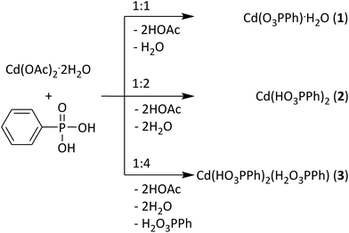
Here, we present the mechanochemical synthesis of three cadmium phenylphosphonates: the cadmium monophenylphosphonate Cd(O3PPh)·H2O (1) (Ph = C6H5)25 and two novel structures (1![[thin space (1/6-em)]](https://www.rsc.org/images/entities/char_2009.gif) :
:![[thin space (1/6-em)]](https://www.rsc.org/images/entities/char_2009.gif) 2 and 1
2 and 1![[thin space (1/6-em)]](https://www.rsc.org/images/entities/char_2009.gif) :
:![[thin space (1/6-em)]](https://www.rsc.org/images/entities/char_2009.gif) 3) (Fig. 1). The structures of the new compounds, Cd(HO3PPh)2 (2) and Cd(HO3PPh)2(H2O3PPh) (3), were determined from powder X-ray diffraction (PXRD) data. Compound (2) contains two monodeprotonated phenylphosphonate ligands. Compound (3) contains a further neutral phenylphosphonic acid ligand. The synthesis of the three compounds was analysed in situ using time resolved synchrotron PXRD. Based on these results, a formation mechanism is proposed.
3) (Fig. 1). The structures of the new compounds, Cd(HO3PPh)2 (2) and Cd(HO3PPh)2(H2O3PPh) (3), were determined from powder X-ray diffraction (PXRD) data. Compound (2) contains two monodeprotonated phenylphosphonate ligands. Compound (3) contains a further neutral phenylphosphonic acid ligand. The synthesis of the three compounds was analysed in situ using time resolved synchrotron PXRD. Based on these results, a formation mechanism is proposed.
Experimental section
Chemicals
The following chemicals were used: cadmium acetate dihydrate (purum p.a., Fluka, Switzerland), phenylphosphonic acid (98%, Acros Organics, USA), and diethyl ether (analytical reagent grade, Fisher Chemical, USA). All chemicals were used without further purification.Synthesis of Cd(O3PPh)·H2O (1)
The synthesis was performed in a vibration ball mill (Pulveristette 23, Fritsch, Germany). Cadmium acetate dihydrate and phenylphosphonic acid were added together in a stainless steel vessel at a molar ratio of 1![[thin space (1/6-em)]](https://www.rsc.org/images/entities/char_2009.gif) :
:![[thin space (1/6-em)]](https://www.rsc.org/images/entities/char_2009.gif) 1 and with a total load of 1 g. Two stainless steel balls (Ø 10 mm, 4 g) were added and the mixture was ground at 50 Hz for 15 min. A damp white powder was obtained and dried in air.
1 and with a total load of 1 g. Two stainless steel balls (Ø 10 mm, 4 g) were added and the mixture was ground at 50 Hz for 15 min. A damp white powder was obtained and dried in air.
Synthesis of Cd(HO3PPh)2 (2)
The synthesis was performed similar to the synthesis of compound (1). Here, the molar ratio of cadmium acetate dihydrate and phenylphosphonic acid was 1![[thin space (1/6-em)]](https://www.rsc.org/images/entities/char_2009.gif) :
:![[thin space (1/6-em)]](https://www.rsc.org/images/entities/char_2009.gif) 2.
2.
Synthesis of Cd(HO3PPh)2(H2O3PPh) (3)
The synthesis was performed following the synthesis procedure described for compound (1). Here, the molar ratio of cadmium acetate dihydrate and phenylphosphonic acid was 1![[thin space (1/6-em)]](https://www.rsc.org/images/entities/char_2009.gif) :
:![[thin space (1/6-em)]](https://www.rsc.org/images/entities/char_2009.gif) 4. The obtained powder was stirred strongly in diethyl ether to remove excess phenylphosphonic acid, filtrated and dried in air.
4. The obtained powder was stirred strongly in diethyl ether to remove excess phenylphosphonic acid, filtrated and dried in air.
With respect to the metal atom, the yields of the reactions are 100%. One has to keep in mind that during the removal of the samples, small amounts remain in the grinding jar. About 95% yield is a realistic estimation. For compound (3) 87% yield was obtained with respect to the metal atom after the cleaning step.
Slurry experiments
Slurry experiments were performed to determine the relative stability of the compounds. Each compound (250 mg) was stirred for 24 h in water (25 mL) under ambient conditions. The solid phase was gained via filtration and analyzed using PXRD, see Fig. S8.†Analytical techniques
PXRD measurements were performed in transmission geometry mode in a 2θ range from 4° to 60°, with a step size of 0.009°, using Cu Kα1 (λ = 1.54056 Å) radiation. The patterns were collected using a diffractometer (D8 Discover, Bruker AXS, Germany) equipped with a Lynxeye detector and a Johansson monochromator in the incident beam. For the structure solution, the measured time per step was 20 s for (2) and 33 s for (3). The PXRD data were indexed using the program DICVOL, implemented in the DASH software.26 The structures were solved using the simulated annealing routine implemented in DASH. For (2) the position of the Cd atom was fixed at (0.5/0.5/0). For (3) the missing hydrogen atoms H3A, H5A, H8A, and H9A were added using PowderCell.27 The final Rietveld refinements were conducted using TOPAS.28 CCDC-1402479 and CCDC-1402480 contain the supplementary crystallographic data for this structure. Copies of the data can be obtained, free of charge, on application to CCDC.†The reactions were investigated in situ using synchrotron XRD. The experiments were performed at the μSpot beamline (Bessy II, Helmholtz Centre Berlin for Materials and Energy, Germany).29 The setup has been reported in detail previously.23 A specially adapted vibration ball mill was used. The compounds were synthesized in a 10 mL custom-made Perspex vessel. The starting materials were ground together with two stainless steel balls (10 mm, 4 g). The experimental conditions were similar to those described before, except that a lower frequency (30 Hz) was applied. The XRD patterns were collected using a two dimensional MarMosaic CCD detector (3072 × 3072 pixels and a point spread function width of about 100 μm). The exposure time was 30 s per measurement, with a delay time of 3–4 s between measurements. For the processing of the scattering images, an algorithm of the computer program FIT2D was used.30 The transformation of the scattering vector (q) to the diffraction angle 2θ for Cu Kα1 radiation allows a direct comparison to the results of the laboratory PXRD measurements.
Results and discussion
Syntheses and structure characterization
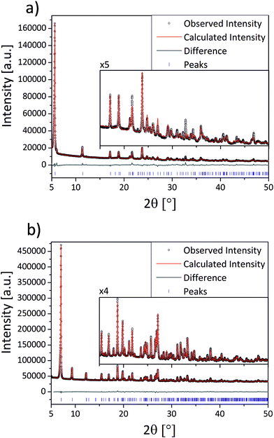
The compounds (1–3) were synthesized via neat grinding (see Experimental section). The PXRD patterns of (1) and (2) show no reflections of the starting materials, indicating a complete reaction (Fig. S1†). The successful mechanochemical synthesis of (1) was confirmed by comparing the PXRD pattern with the calculated pattern from the known structure (Fig. 2).25 The crystal structures of (2) and (3) were solved from the PXRD patterns. For both compounds (2) and (3) the final Rietveld and difference plots are shown in Fig. 3. Table 1 summarizes the crystallographic data. In the PXRD pattern of (2) a weak reflection at 6.1° indicates the formation of (1) as a side product. A Rietveld refinement with both structures results in an amount of (1) close to 1%.28 The synthesis of (3) contains a cleaning step to remove excess phenylphosphonic acid. The PXRD pattern of (3) before the cleaning step shows reflections of phenylphosphonic acid, which is reasonable because the acid is used in excess (Fig. S2†). After stirring in diethyl ether, the corresponding PXRD pattern shows no reflections of the starting materials (Fig. S2†). The diffraction patterns of all three compounds are characterized by a strong reflection in the low 2θ range ((1): 6.1°, (2): 5.7° and (3): 7.1°). These characteristic reflections can be used for an unambiguous phase identification.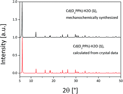 | ||
| Fig. 2 Comparison of the measured PXRD pattern of (1) (black) and the calculated (red) PXRD pattern for Cd(O3PPh)·H2O.25 | ||
| 1 (ref. 25) | 2 | 3 | |
|---|---|---|---|
| Empirical formula | CdC6H7O4P | CdC12H12O6P2 | CdC18H19O9P3 |
| Formula weight/g mol−1 | 286.49 | 426.58 | 584.67 |
| Crystal system | Orthorhombic | Triclinic | Monoclinic |
| Space group | Pmn21 |
P![[1 with combining macron]](https://www.rsc.org/images/entities/char_0031_0304.gif) |
P21/c |
| a/Å | 5.860(4) | 16.1586(16) | 5.732864(91) |
| b/Å | 14.459(14) | 5.60337(54) | 24.84899(42) |
| c/Å | 5.054(3) | 4.46652(33) | 14.40494(22) |
| α/° | 90 | 119.6039(72) | 90 |
| β/° | 90 | 94.4432(77) | 91.1232(15) |
| γ/° | 90 | 101.7890(80) | 90 |
| V/Å3 | 428.2(6) | 336.556(62) | 2051.674(57) |
| Z | 2 | 1 | 4 |
| D calc/g cm−3 | 2.22 | 2.09479(39) | 1.892851(51) |
| R wp | 0.0697 | 0.0416 | |
| R Bragg | 0.02694 | 0.02084 | |
| GOF | 5.08 | 4.00 |
Structure description
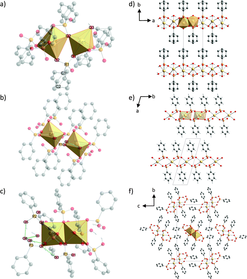
The structure of (1) is shown in Fig. 4d along the c-axis. The structure is isomorphic to a group of divalent metal phenylphosphonate monohydrates and was described in detail by Cao et al.25 The Cd2+ ion is six-fold coordinated in a distorted octahedron. The coordination environment consists of six oxygen atoms from four different phenylphosphonate ligands and one water molecule. These CdO6-octahedrons are directly corner-connected (see Fig. 4a). An additional connection is formed by the phosphonate groups. The inorganic part of the phenylphosphonate ligands and the Cd2+ ion form a layer structure. The organic part points into the interlayer space, as is often observed for metal phosphonates. The position of the phenyl rings is disordered. The two possible positions are oriented orthogonal to each other along the C1–C2 axis.The structure of (2) is depicted in Fig. 4e along the c-axis. Selected bond lengths and angles are given in Table S1.† The Cd2+ ion is coordinated by six oxygen atoms from six different phenylphosphonate ligands in a distorted octahedron (Fig. 4b). The oxygen atoms of the phenylphosphonate ligands are involved in the coordination of three different Cd2+ ions. Four longer bonds (2.5319(3) Å and 2.5762(3) Å) and two shorter bonds (2.2262(2) Å) can be distinguished. The O–Cd–O angles range from 72.59(1)° to 107.41(1)°. Since all of the oxygen atoms coordinate to only one Cd2+ ion, there is no direct connection between the octahedrons. Here, the connection is established by the phosphonate groups (see Fig. 4b), resulting in a typical layer structure for the inorganic part of the compound including the isolated CdO6-octahedrons. The phenyl rings point into the interlayer space. The phenyl rings are ordered alternately above and below the layer, slightly tilted with respect to the layer plane. The asymmetric unit contains only monodeprotonated phenylphosphonate ligands. The position of the acidic hydrogen atom could not be determined directly. Based on the lengths of the P–O bonds (1.4196(1) Å (O2), 1.5388(1) Å (O3) and 1.5796(1) Å (O1)), O2 can be identified as the double bonded oxygen atom. A strong hydrogen bond connects the oxygen atom O1 with another phenylphosphonate molecule (O2), which additionally stabilizes the structure (dO–O = 2.5569(2) Å).
The structure of (3) is shown in Fig. 4f along the a-axis. Selected bond lengths and angles are given in Table S2.† The Cd2+ ion is also coordinated by six oxygen atoms from six different phenylphosphonates in a distorted octahedron (Fig. 4c). The six Cd–O bonds range from 2.2439(7) Å to 2.5202(5) Å and the O–Cd–O angle ranges from 72.681(16)° to 108.637(26)°. The three phenylphosphonate ligands coordinate differently. The neutral phenylphosphonic acid coordinates monodentately to one Cd2+ ion. The P–O bond length for the coordinating oxygen atom (O7) is 1.5525(6) Å and for the non-coordinating oxygen atoms the bond lengths are 1.5299(7) Å (O9) and 1.5422(4) Å (O8). The second ligand coordinates with two oxygen atoms to two different Cd2+ ions. The third oxygen atom (O5) is non-coordinating and carries the acidic hydrogen atom. The P–O5 bond length amounts to 1.5609(4) Å. For the coordinating oxygen atoms the P–O bond lengths are 1.5220(4) Å (O4) and 1.5708(5) Å (O6). This phenylphosphonate ligand is monodeprotonated. The third phenylphosphonate ligand is also monodeprotonated. Two oxygen atoms are coordinated to three different Cd2+ ions. The oxygen atom O2 is bridging two of them. The P–O2 bond length is 1.5337(4) Å. The non-coordinating oxygen atom (O3) is protonated. The P–O3 bond length is 1.5271(6) Å. The P–O bond length for the non-bridging coordinating oxygen atom (O1) is 1.5333(4) Å. As a result of this coordination, pairs of edge connected CdO6-octahedrons are formed (see Fig. 4c). These pairs are connected to two other pairs in opposite directions via four phosphonate groups. Two neutral phenylphosphonic acid units are located adjacent to this pair. The arrangement results in a double chain built by pairs of CdO6-octahedrons and the inorganic part of the phenylphosphonate. The phenyl rings point into the interchain space. The neutral ligands are located at the smaller edges of the chain and the protonated ligands are located above and below the chain. The chains are connected via π–π-stacking of parallel orientated phenyl rings and build a layered superstructure. The two orientations for the CdO6-octahedron pairs lead to two orientations in the resulting chain and layered structure. The layers are stacked in an alternating manner. Here, the acidic hydrogen atoms are located at the non-coordinating oxygen atoms. The orientation of the hydrogen atoms was estimated based on the direction of the hydrogen bonds. Two strong hydrogen bonds (dO9–O5 = 2.5554(5) Å and dO5–O8 = 2.4135(6) Å) stabilise the structure. The latter value is short, but was also observed for other phosphoric acids.32 Additionally, moderate (dO3–O7 = 2.8242(6) Å) and weak (dO8–O3 = 3.2504(8) Å) hydrogen bonds are formed.
Mechanistic studies
All syntheses were investigated using in situ synchrotron XRD. The milling reactions were performed at 30 Hz. Under these conditions, the same products are formed during an increased reaction time, which facilitates the detection of intermediates that can be detected more clearly under these conditions. The data at t = 0 s represent the XRD pattern of the mixture without any milling. All synthesis pathways can be divided into five phases.A 2D plot of the XRD data for the synthesis of (1) is shown in Fig. 5a. The data collected at t = 0 s represent the reflections of the starting materials (phase 1). After 30 s a peak at 2θ = 7.1° appears, which can be assigned to (3) (phase 2). 30 s later a reflection at 6.1° indicates the formation of (1) (phase 3). During the next few minutes the intensity of the reflections of the starting materials decreases and it vanishes after 4:30 min (start of phase 4). The intensities of the reflections for (3) also start to decrease, while the number and intensity of the product reflections increase. After 14 min only the reflections of the final product can be detected (phase 5).
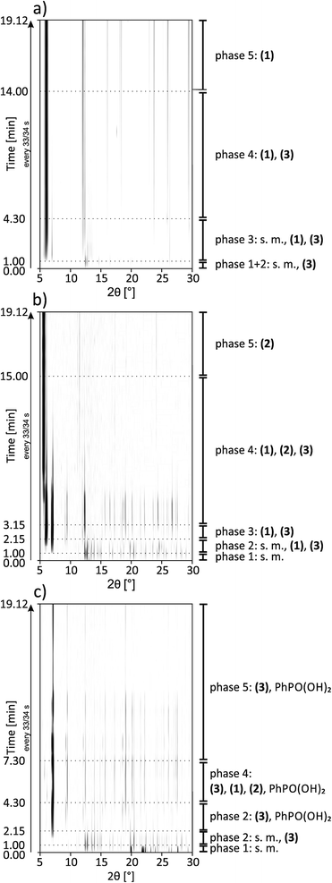 | ||
| Fig. 5 2D plots of synchrotron XRD data for the synthesis of (a) (1), (b) (2) and (c) (3) with a description of the detected compounds; s.m. = starting materials. | ||
A 2D plot of the XRD data of the synthesis of (2) is depicted in Fig. 5b. In the first phase only the starting materials can be detected. After 1 min of milling, different reflections indicate the formation of (1) and (3) (phase 2). The strongest reflections are at 6.1° and 7.1°, respectively. The reflections for (3) are more pronounced. During this phase, the reflection intensities of the starting materials decrease. After 2:15 min the reflections of the starting materials vanish and only peaks for both of the intermediates can be detected (phase 3). In phase 4 a reflection at 5.7° indicates the formation of the final product. The intensity is very weak compared to the intensity of the reflections at 6.1° and 7.1°. After 6 min of milling, the reflection intensities of the intermediates start to decrease, while at the same time those of the product increase. With increasing milling time, only the strongest reflections of the intermediates can be detected. After 9 min of further milling all the reflections of (3) disappear. Reflections of the final product and a very low contribution of (1) at 6.1° can be detected (phase 5). This additional peak remains unchanged during the observed synthesis. The same phenomenon could be observed in the final PXRD pattern of the product of the laboratory synthesis (see Fig. S1†).
A 2D plot of the XRD data of the synthesis of (3) is shown in Fig. 5c. At the beginning, only the starting materials can be detected. After 1 min of milling a peak at 7.1° indicates the formation of the final product. In the next minute the reflections of cadmium acetate dihydrate disappear (e.g. 12.6°). The ones belonging to phenylphosphonic acid (e.g. 20.4°) persist since the acid is used in excess (phase 3). After 4:30 min a reflection at 6.1° can be detected (phase 4). This reflection indicates the intermediate formation of (1). The peak remains observable until 6:45 min. At 5:30 min a reflection at 5.7° indicates the formation of (2). The reflection can be detected for the next two minutes. In the fifth phase, reflections of the final product and phenylphosphonic acid can be detected. During the last eleven minutes of the reaction, the intensities of the reflections changes. These non-systematic changes are an artifact of the measurement and stem from different amounts of powder in the beam path. A close inspection of Fig. 5c shows that the reflections disappear at a certain time (12 minutes) and reappear again after 4 minutes. Two aspects are important: (i) three reflections of compound (3) persist during this period in a weaker form and (ii) no change in the crystallite size (the widths of the reflections stay the same) was observed before or after this period. We would expect a decrease in the crystallite size before an amorphous product is observed.
In situ measurements of mechanochemical reactions are a new field. Based on recent publications, mechanochemical reactions proceed either directly from the starting materials to the final product or are characterized by the formation of an intermediate phase.21,23,33,34 Beldon et al. also found indications for an Ostwald ripening process for the synthesis of ZIF.35 Summarizing, for all three investigated compounds, a synthesis process involving different intermediate steps could be observed. The formations of (1) and (3) under milling conditions are much faster than the formation of (2). Compound (3) seems kinetically favored. Using a 1![[thin space (1/6-em)]](https://www.rsc.org/images/entities/char_2009.gif) :
:![[thin space (1/6-em)]](https://www.rsc.org/images/entities/char_2009.gif) 1 and 1
1 and 1![[thin space (1/6-em)]](https://www.rsc.org/images/entities/char_2009.gif) :
:![[thin space (1/6-em)]](https://www.rsc.org/images/entities/char_2009.gif) 4 starting stoichiometry, reflections of (3) can be detected after 30 s and one minute, respectively. Reflections of (1) can be detected after one minute using a 1
4 starting stoichiometry, reflections of (3) can be detected after 30 s and one minute, respectively. Reflections of (1) can be detected after one minute using a 1![[thin space (1/6-em)]](https://www.rsc.org/images/entities/char_2009.gif) :
:![[thin space (1/6-em)]](https://www.rsc.org/images/entities/char_2009.gif) 1 starting stoichiometry. Reflections of both compounds can be detected as well after one minute using a 1
1 starting stoichiometry. Reflections of both compounds can be detected as well after one minute using a 1![[thin space (1/6-em)]](https://www.rsc.org/images/entities/char_2009.gif) :
:![[thin space (1/6-em)]](https://www.rsc.org/images/entities/char_2009.gif) 2 starting stoichiometry, which finally leads to (2). The reflections of the starting materials vanish prior to the formation of (2). This indicates that (2) is directly formed from intermediates of (1) and (3). The same behavior could be observed for the synthesis of (3). Here, the final product is built first and (1) is formed intermediately. Shortly thereafter, reflections of (2) can be detected and those of (1) start to decrease. Further experiments showed that it is also possible to synthesize (2) by milling (1) and (3) at a molar ratio of 1
2 starting stoichiometry, which finally leads to (2). The reflections of the starting materials vanish prior to the formation of (2). This indicates that (2) is directly formed from intermediates of (1) and (3). The same behavior could be observed for the synthesis of (3). Here, the final product is built first and (1) is formed intermediately. Shortly thereafter, reflections of (2) can be detected and those of (1) start to decrease. Further experiments showed that it is also possible to synthesize (2) by milling (1) and (3) at a molar ratio of 1![[thin space (1/6-em)]](https://www.rsc.org/images/entities/char_2009.gif) :
:![[thin space (1/6-em)]](https://www.rsc.org/images/entities/char_2009.gif) 1. Acetic acid and water were added to meet the original synthesis conditions. The synthesis is successful but a higher energy is needed (see Fig. S7†). 15 min of milling at 50 Hz results in a mixture of all three compounds. 60 min of milling at the same frequency leads to the pure compound (2).
1. Acetic acid and water were added to meet the original synthesis conditions. The synthesis is successful but a higher energy is needed (see Fig. S7†). 15 min of milling at 50 Hz results in a mixture of all three compounds. 60 min of milling at the same frequency leads to the pure compound (2).
All compounds involved in the synthesis can be identified as one of the cadmium phenylphosphonates or as starting materials. There are no other intermediates, such as mixed salts or amorphous phases. All reactions can be described using the following equation (with x = 1, 2, 3, and y = 0, 1):
This equation clearly shows that during the reaction acetic acid and water are released. Therefore, the dry milling synthesis is liquid-assisted by its side products. Indeed, all products were wet after milling. Based on these results, a reaction mechanism like the classic hot-spot-theory and the magma-plasma model36 can be ruled out.37 Within the magma-plasma model and its expected high energies, more fragmental intermediates and distinctly amorphous phases would be expected. Ma et al. recently described a milling reaction mechanism based on the thorough stirring of very small solid particles.38 We have observed, in agreement with the literature, that the reaction speed can be easily increased by increasing the applied frequency. Furthermore, the diffusion rate in liquid assisted grinding reactions is higher than in dry ones. It has been shown that acetic acid, as a side product, acts as an assisting liquid in self-sustaining reactions after a short initial activation.39 The decreasing intensity of the reflections of the starting materials and intermediates, together with the increasing reflections of the products, shows that the described diffusion mechanism can be used to explain the formation mechanism of cadmium phenylphosphonates.
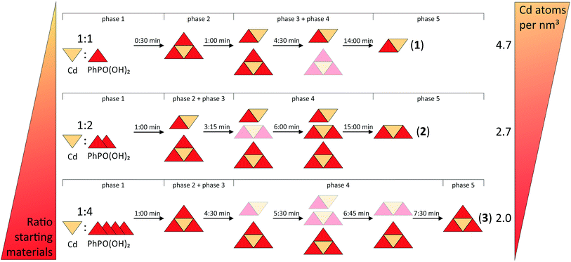
Fig. 6 provides a schematic overview of the reaction pathways. The influence of the two directing factors, thermodynamic stability and the stoichiometric ratio of the starting materials, which were identified for the nature of the product, are illustrated. The slurry experiments showed that compound (1) is the most stable one (see Fig. S8†). The thermodynamic stability of metal organic compounds is connected with the density of the framework. For frameworks with the same composition it was shown that a more dense structure (expressed by the metal atom per nm3 ratio) also has a lower total energy.40,41 Beldon et al. showed that the mechanochemical formation of metal organic frameworks can follow Ostwald’s rule of stages. The first types with a lower density of central atoms are formed intermediately.35 The final product is the one with the highest density. This trend is not that clear for compounds with different compositions. Compound (3) has the lowest density, with 2.0 Cd atoms per nm3. Consistently, (3) is formed first in all three reactions. Compound (1) shows the highest value with 4.7 Cd atoms per nm3. This could be the reason why the compound remains stable in a small amount for the whole milling time during the synthesis of (2). This reaction also shows the influence of the second directing factor, the composition of the starting materials. The 1![[thin space (1/6-em)]](https://www.rsc.org/images/entities/char_2009.gif) :
:![[thin space (1/6-em)]](https://www.rsc.org/images/entities/char_2009.gif) 1 (cadmium acetate dihydrate: phenylphosphonic acid) and the 1
1 (cadmium acetate dihydrate: phenylphosphonic acid) and the 1![[thin space (1/6-em)]](https://www.rsc.org/images/entities/char_2009.gif) :
:![[thin space (1/6-em)]](https://www.rsc.org/images/entities/char_2009.gif) 2 syntheses result mainly in a stoichiometric product. The influence of both directing factors can be seen in the PXRD pattern (see Fig. S3†) of the 1
2 syntheses result mainly in a stoichiometric product. The influence of both directing factors can be seen in the PXRD pattern (see Fig. S3†) of the 1![[thin space (1/6-em)]](https://www.rsc.org/images/entities/char_2009.gif) :
:![[thin space (1/6-em)]](https://www.rsc.org/images/entities/char_2009.gif) 3 synthesis, where (2) (with 2.7 Cd atoms per nm3) and (3) are formed at the same time. Only with an excess of phenylphosphonic acid can (3) be obtained as the final product.
3 synthesis, where (2) (with 2.7 Cd atoms per nm3) and (3) are formed at the same time. Only with an excess of phenylphosphonic acid can (3) be obtained as the final product.
A comparison of the results of the in situ investigations of the mechanochemical syntheses of cadmium phenylphosphonates with the previously reported in situ investigations under hydrothermal and ultrasonic conditions is difficult. In all three investigated systems, the phosphonates carry functionalised organic groups which can also coordinate to the metal ion. The syntheses were carried out from aqueous solutions with the addition of inorganic bases. Nevertheless, in the investigations of the crystallisation of calcium aminoethylphosphonate and copper(II) phosphonoethanesulfonate, crystalline intermediates were also observed. They are not based on the metal![[thin space (1/6-em)]](https://www.rsc.org/images/entities/char_2009.gif) :
:![[thin space (1/6-em)]](https://www.rsc.org/images/entities/char_2009.gif) phosphonate ligand ratio, but on the presence of small molecules like water or hydroxide ions in the crystal structure.15,16 A correlation between the crystal density and the thermodynamic stability of the compounds was estimated.
phosphonate ligand ratio, but on the presence of small molecules like water or hydroxide ions in the crystal structure.15,16 A correlation between the crystal density and the thermodynamic stability of the compounds was estimated.
Conclusions
The successful mechanochemical syntheses of three cadmium phenylphosphonates indicates that mechanochemistry is ideally suited for synthesizing metal phosphonates. With this powerful synthesis tool it is possible to synthesize rapidly and efficiently both known and novel phosphonates. The crystal structures of the two new compounds, (2) and (3), were solved from PXRD data. They contain monodeprotonated phenylphosphonate and neutral phenylphosphonic acid ligands. The synthesis pathways of all three compounds were investigated in situ. A diffusion mechanism is corroborated by our findings. Intermediates could be detected and identified. The kinetically favored product (3) could always be detected during the syntheses. The thermodynamic stability of the compounds and the stoichiometric ratio of the starting materials are the two directing factors for the synthesis of the final products.Acknowledgements
The authors are grateful for the funding received by the DFG program “Crystalline non-equilibrium compounds” (grant number Em198/3-2).References
- E. Brunet, H. M. H. Alhendawi, C. Cerro, M. J. de la Mata, O. Juanes and J. C. Rodriguez-Ubis, Chem. Eng. J., 2010, 158, 333–344 CrossRef CAS.
- T. Y. Ma, X. Z. Lin, X. J. Zhang and Z. Y. Yuan, New J. Chem., 2010, 34, 1209–1216 RSC.
- R. Sen, D. Saha, D. Mal, P. Brandao, G. Rogez and Z. Lin, Eur. J. Inorg. Chem., 2013, 2013, 5020–5026 CAS.
- G. Alberti, M. Casciola, R. Palombari and A. Peraio, Solid State Ionics, 1992, 58, 339–344 CrossRef CAS.
- R. M. P. Colodrero, P. Olivera-Pastor, A. Cabeza, M. Papadaki, K. D. Demadis and M. A. G. Aranda, Inorg. Chem., 2010, 49, 761–768 CrossRef CAS PubMed.
- R. Thakkar and U. Chudasama, J. Iran. Chem. Soc., 2010, 7, 202–209 CrossRef CAS.
- P. H. Mutin, G. Guerrero and A. Vioux, C. R. Chim., 2003, 6, 1153–1164 CrossRef CAS.
- B. Bujoli, P. Janvier and M. Petit, Metal Phosphonate Chemistry: From Synthesis to Applications, The Royal Society of Chemistry, 2012, ch. 13, pp. 420–437 Search PubMed.
- A. Clearfield, Metal Phosphonate Chemistry: From Synthesis to Applications, The Royal Society of Chemistry, 2012, ch. 1, pp. 1–44 Search PubMed.
- A. Clearfield, Curr. Opin. Solid State Mater. Sci., 2002, 6, 495–506 CrossRef CAS.
- K. Maeda, Microporous Mesoporous Mater., 2004, 73, 47–55 CrossRef CAS.
- N. Stock and T. Bein, Angew. Chem., Int. Ed., 2004, 43, 749–752 CrossRef CAS PubMed.
- J. Chen, J. Bai, H. Chen and J. Graetz, J. Phys. Chem. Lett., 2011, 2, 1874–1878 CrossRef CAS.
- J. M. Bai, J. Hong, H. Y. Chen, J. Graetz and F. Wang, J. Phys. Chem. C, 2015, 119, 2266–2276 CAS.
- C. Schmidt, M. Feyand, A. Rothkirch and N. Stock, J. Solid State Chem., 2012, 188, 44–49 CrossRef CAS.
- M. Feyand, A. Hubner, A. Rothkirch, D. S. Wragg and N. Stock, Inorg. Chem., 2012, 51, 12540–12547 CrossRef CAS PubMed.
- L. H. Schilling and N. Stock, Dalton Trans., 2014, 43, 414–422 RSC.
- M. Klimakow, P. Klobes, A. F. Thunemann, K. Rademann and F. Emmerling, Chem. Mater., 2010, 22, 5216–5221 CrossRef CAS.
- T. Friscic, D. G. Reid, I. Halasz, R. S. Stein, R. E. Dinnebier and M. J. Duer, Angew. Chem., Int. Ed., 2010, 49, 712–715 CrossRef CAS PubMed.
- L. Tröbs, M. Wilke, W. Szczerba, U. Reinholz and F. Emmerling, CrystEngComm, 2014, 16, 5560–5565 RSC.
- T. Friscic, I. Halasz, P. J. Beldon, A. M. Belenguer, F. Adams, S. A. J. Kimber, V. Honkimaki and R. E. Dinnebier, Nat. Chem., 2013, 5, 66–73 CrossRef CAS PubMed.
- D. Gracin, V. Strukil, T. Friscic, I. Halasz and K. Uzarevic, Angew. Chem., Int. Ed., 2014, 53, 6193–6197 CrossRef CAS PubMed.
- L. Batzdorf, F. Fischer, M. Wilke, K.-J. Wenzel and F. Emmerling, Angew. Chem., Int. Ed., 2015, 54, 1799–1802 CrossRef CAS PubMed.
- K. Uzarevic, I. Halasz and T. Friscic, J. Phys. Chem. Lett., 2015, 6, 4129–4140 CrossRef CAS PubMed.
- G. Cao, V. M. Lynch and L. N. Yacullo, Chem. Mater., 1993, 5, 1000–1006 CrossRef CAS.
- W. I. F. David, K. Shankland, J. van de Streek, E. Pidcock, W. D. S. Motherwell and J. C. Cole, J. Appl. Crystallogr., 2006, 39, 910–915 CrossRef CAS.
- G. Nolze and W. Kraus, Powder Diffr., 1998, 13, 256–259 Search PubMed.
- Bruker AXS, Topas version 4.2, 2009 Search PubMed.
- O. Paris, C. H. Li, S. Siegel, G. Weseloh, F. Emmerling, H. Riesemeier, A. Erko and P. Fratzl, J. Appl. Crystallogr., 2007, 40, S466–S470 CrossRef CAS.
- A. P. Hammersley, S. O. Svensson, M. Hanfland, A. N. Fitch and D. Hausermann, High Pressure Res., 1996, 14, 235–248 CrossRef.
- J. I. Langford and D. Louer, Rep. Prog. Phys., 1996, 59, 131–234 CrossRef CAS.
- D. Corbridge, The structural chemistry of phosphorus, Elsevier, Amsterdam, 1974 Search PubMed.
- F. Fischer, G. Scholz, L. Batzdorf, M. Wilke and F. Emmerling, CrystEngComm, 2015, 17, 824–829 RSC.
- I. Halasz, A. Puskaric, S. A. J. Kimber, P. J. Beldon, A. M. Belenguer, F. Adams, V. Honkimaki, R. E. Dinnebier, B. Patel, W. Jones, V. Strukil and T. Friscic, Angew. Chem., Int. Ed., 2013, 52, 11538–11541 CrossRef CAS PubMed.
- P. J. Beldon, L. Fabian, R. S. Stein, A. Thirumurugan, A. K. Cheetham and T. Friscic, Angew. Chem., Int. Ed., 2010, 49, 9640–9643 CrossRef CAS PubMed.
- P. A. Thiessen, K. Meyer and G. G. Heinicke, Grundlagen der Tribochemie, Akademie Verlag, Berlin-Ost, Berlin, 1967 Search PubMed.
- S. L. James, C. J. Adams, C. Bolm, D. Braga, P. Collier, T. Friscic, F. Grepioni, K. D. M. Harris, G. Hyett, W. Jones, A. Krebs, J. Mack, L. Maini, A. G. Orpen, I. P. Parkin, W. C. Shearouse, J. W. Steed and D. C. Waddell, Chem. Soc. Rev., 2012, 41, 413–447 RSC.
- X. H. Ma, W. B. Yuan, S. E. J. Bell and S. L. James, Chem. Commun., 2014, 50, 1585–1587 RSC.
- A. Pichon, A. Lazuen-Garay and S. L. James, CrystEngComm, 2006, 8, 211–214 RSC.
- I. Halasz, T. Friscic, S. A. J. Kimber, K. Uzarevic, A. Puskaric, C. Mottillo, P. Julien, V. Strukil, V. Honkimaki and R. E. Dinnebier, Faraday Discuss., 2014, 170, 203–221 RSC.
- D. W. Lewis, A. R. Ruiz-Salvador, A. Gomez, L. M. Rodriguez-Albelo, F. X. Coudert, B. Slater, A. K. Cheetham and C. Mellot-Draznieks, CrystEngComm, 2009, 11, 2272–2276 RSC.
Footnote |
† Electronic supplementary information (ESI) available: Crystallographic information files, tables with selected bond lengths of compounds (2) and (3); PXRD patterns of the starting materials, compounds (1), (2) and (3) (before and after the cleaning step), and of the product mixture of the mechanochemical synthesis with a 1![[thin space (1/6-em)]](https://www.rsc.org/images/entities/char_2009.gif) : :![[thin space (1/6-em)]](https://www.rsc.org/images/entities/char_2009.gif) 3 ratio of the starting materials; enlarged 2D plots of the in situ investigations of the syntheses of compounds (1–3); PXRD patterns of the products of the mechanochemical syntheses with compounds (1) and (3) as starting materials; and PXRD patterns of the products of the slurry experiments. CCDC 1402479 and 1402480. For ESI and crystallographic data in CIF or other electronic format see DOI: 10.1039/c6ra01080f 3 ratio of the starting materials; enlarged 2D plots of the in situ investigations of the syntheses of compounds (1–3); PXRD patterns of the products of the mechanochemical syntheses with compounds (1) and (3) as starting materials; and PXRD patterns of the products of the slurry experiments. CCDC 1402479 and 1402480. For ESI and crystallographic data in CIF or other electronic format see DOI: 10.1039/c6ra01080f |
| This journal is © The Royal Society of Chemistry 2016 |

