Copolymers of ionic liquids with polymeric or metallocomplex chromophores for quasi-solid-state DSSC applications

Panagiotis Giannopoulosa, Aikaterini K. Andreopoulou*ab, Charalampos Anastasopoulosa, Dimitrios Raptisbc, Georgia Sfyribd, Joannis K. Kallitsisab and Panagiotis Lianosbc
aDepartment of Chemistry, University of Patras, University Campus, Rio-Patras, GR26504, Greece. E-mail: andreopo@upatras.gr
bFoundation for Research and Technology Hellas/Institute of Chemical Engineering Sciences (FORTH/ICE-HT), Platani Str., Patras, GR26504, Greece
cDepartment of Chemical Engineering, University of Patras, 26504 Patras, Greece
dDepartment of Physics, University of Patras, 26504 Patras, Greece

Received 21st December 2015 , Accepted 30th December 2015

First published on 6th January 2016


Abstract

The development of copolymers based on ionic liquid vinyl monomers of the imidazole family combined with polymerizable chromophoric units is presented herein. For this end, ruthenium complexes bearing polymerizable vinyl groups or ω-end vinyl rr-poly(3-alkyl thiophene) were prepared and copolymerized with the ionic liquid monomers under free radical polymerization conditions, affording chromophore/polyelectrolyte combinations. Homopolymer ionic liquids were also synthesized to select the optimum conditions for the copolymers thereafter. All the monomers and polymers were characterized for their optical properties, and were also structurally characterized using various complementary techniques. Selected copolymers and homopolymers were tested in quasi-solid-state sensitized solar cells based on titania and regioregular poly(3-hexyl thiophene) acting as a hole-transporting semiconducting polymer. The ionic liquid, which is miscible with the hole-conductor and can be deposited with the latter, provides a functionality that, in some cases, supports an increase in open-circuit voltage, thus increasing cell efficiency.

Introduction

Over the last years, much research has focused on the replacement of silicon-based photovoltaic devices. This is mainly due to their high cost of production and the limited range of applicable materials, which has turned research interest towards organic photovoltaic devices (OPVs), where the active layers of the device mainly consist of organic materials.1 OPVs show some advantages regarding cost and environmental issues despite their lower efficiency in comparison to the inorganic light converters currently commercially available. One technology that has shown increased conversion efficiency among OPVs is dye-sensitized solar cells (DSSCs).2

In a typical DSSC, an inorganic semiconductor, usually TiO2[thin space (1/6-em)]3–6 or ZnO,7,8 acts as an electron acceptor and transporter. The semiconductor also supports the sensitizer, i.e. a material that absorbs visible light and injects the photogenerated electron into the conduction band of the supporting (acceptor) semiconductor. In DSSCs, a dye plays the role of the sensitizer. In this role, the dye must have anchoring groups to form stable bonds with the semiconductor's surface. Such anchoring groups are mainly carboxylic, although other anchors have been suggested, such as the perfluorophenyl group, which was recently reported by our group.9,10 The remaining functional components of a DSSC are a counter electrode – usually carrying Pt nanoparticles as the catalyst, although various attempts have been reported aimed at the replacement of Pt, mainly with carbon hybrids11 – and an electrolyte.12–14

The electrolyte in DSSCs is very important because it provides the required ionic conductivity and helps dye regeneration through charge transfer reactions with the dye molecules. Liquid electrolytes present a major drawback in the use of DSSCs due to solvent evaporation and a subsequent reduction of device lifetime and performance, especially when the device is not perfectly sealed.15 Thus, the replacement of typical solvents (or solvent mixtures) with solid or quasi-solid electrolytes is a very interesting and active field of research.16 Commonly, ionic liquids, p-type hole-transport organic semiconductors, plastic crystals and polymer gel electrolytes have been used instead of the typical liquid ones. This kind of electrolyte shows long-term stability, although in many cases the efficiency is lower than typical DSSCs.17–25

ILs are widely studied organic salts and have gained much attention for a wide range of applications in various chemical and industrial fields. This is attributed to their unique properties, such as high ionic conductivity, good thermal, chemical and electrochemical stability and low vapour pressure.26,27 Due to these properties, ILs are commonly used as solvents for organic synthesis or catalysis (green solvents) and for polymerization processes, such as free radical polymerization28,29 and atom transfer radical polymerization (ATRP).30,31 Their use is also extended into other applications, such as lithium batteries,32–34 light emitting devices35 and electrochemical capacitors.36 Various IL chemical structures have been reported employing, for example, the imidazolium or pyrrolidinium moieties as cations and hexafluorophosphate or tetrafluoroborate as anions. In the field of DSSCs, imidazolium-based ionic liquids,37–39 or more recently electrolytes based on these ionic liquids,40,41 have been studied.

Polymerizable ionic liquid monomers and their respective polymers ​(PILs) are now considered as a specific field in polymer science. These polymeric ionic liquids show increased thermal stability, combined with interesting electrochemical properties. One of the most studied imidazolium-based PILs is poly[1-(4-vinylbenzyl)-3-butyl imidazolium tetrafluoroborate] (PVBT), which remains stable up to 300 °C,42 is highly polar, is soluble in solvents such as N,N-dimethylformamide (DMF), dimethylsulfoxide (DMSO) or acetonitrile because of its ionic nature, and at the same time is hydrophobic. PILs are identified as exotic polyelectrolytes for various applications, like in DSSCs, in which they could effectively replace the liquid electrolytes used up to now.43–46 Although a lot of progress has been reported in this field, with recent works aiming at the formation of IL-based hybrids,47,48 the use of IL-based polymer gels has so far only resulted in a few successful studies,28,49 with even less employing copolymers.50 Despite this, ongoing research is focusing on this topic, since ILs can overcome solvent electrolyte leakage, whereas the combination of an IL-based electrolyte with a dye could improve cell stability without sacrificing the overall efficiency of the cell.51

An optimum concept for such organic solvent-free quasi-solid-state DSSCs could be the simultaneous incorporation of chromophores and ILs, which could broaden absorption and ion transfer in the final device. These facts urged us to investigate the use of PILs as electrolytes in DSSC applications and to compare them with copolymers based on ILs and suitable dyes. Both organic dyes and metallocomplexes were employed, in order to compare the applicability of organic versus organometallic dyes, even though the drawbacks of ruthenium (or other metal) containing dyes, such as toxicity and availability, needs also to be taken into consideration. Therefore, in the present study, we employed two polymerizable vinyl-ILs, namely 1-(4-vinylbenzyl)-3-methyl imidazolium tetrafluoroborate (VBMImT)52 and 1-vinyl-3-hexyl-imidazolium bromide (VHImBr)53 and polymerizable dye (macro)molecules, a low molecular weight ω-end vinyl terminated regioregular poly(3-alkylthiophene)54 and a vinylphenyl-bipyridine ruthenium complex with two bipyridines as co-ligands,55 in order to prepare homopolymer and copolymer PILs. The polymerizations were carried out under various conditions in order to achieve the best yields for the homopolymers, but also as a first test regarding the forthcoming copolymerizations. Through this route, the homopolymers PVBMImT and PVHImBr were synthesized, followed by the synthesis of copolymers based on the ionic liquids combined with the ω-end vinyl-poly(3-octyl-thiophene) or the (vinylphenyl-bipyridine)-Ru(II)-di(bipyridine) complex. Both the homopolymer and copolymer PILs were structurally characterized and their optical properties evaluated. Such materials were then employed in the fabrication of solar cells and their performance was then tested.

Experimental section

Materials

ω-End vinyl-poly(3-octylthiophene) (vinyl-P3OT)54 and Ru(bpy)2(styrylbpy)55 were prepared according to literature. The synthetic procedures for the ionic liquid monomers VBMImT52 and VHImBr53 are given in the ESI.

All the solvents and reagents were purchased from Sigma Aldrich, Alfa Aesar or Acros Organics and were used without further purification unless otherwise stated. All the reactions were carried out under an argon atmosphere.

Tetrahydrofuran (THF) was dried and distilled just before use over sodium wire in the presence of benzophenone. Acetonitrile (MeCN) was dried and distilled over calcium hydride (CaH2). 2,2′-Azobis(2-methylpropionitrile) (AIBN) was recrystallized using methanol (MeOH).

Dye sensitizer N719 was obtained from Solaronix, conductive polymer PEDOT:PSS (Baytron P) from H. C. Starck, regioregular poly(3-hexyl thiophene) from Rieke Metals and silver ink (5007E) from DuPont.

Characterization methods

1H NMR spectra were recorded on a Bruker Advance DPX 400.13 MHz spectrometer, using MeOH-d1, DMSO-d6 or CDCl3 as the solvents with TMS as the internal standard.

Thermogravimetric analysis (TGA) was carried out on ca. 8 mg samples contained in alumina crucibles in a Labsys TM TG apparatus of Setaram under nitrogen and at a heating rate of 10 °C min−1.

IR spectra were recorded on an ALPHA-P diamond ATR spectrometer of Bruker Optics GmbH.

Mass spectra were recorded on a Waters Acquity ESI-MS system with a Waters 2966 Photodiode Array detector coupled to a Waters Micromass ZQ mass spectrometer. A single-quadrupole Quattro micro mass spectrometer (ACQUITY SQ Detector) equipped with an electrospray ionization (ESI) interface was used for analytical detection. ESI-MS was operated in positive mode under the following operating parameters: capillary voltage, 3.5 kV; cone voltage, 30 V; source temperature, 80 °C; desolvation temperature, 300 °C; desolvation gas (nitrogen), 5500 L h−1; cone gas (nitrogen), 50 L h−1. All the data were acquired and processed using Masslynx 4.1 software (Waters Corp., MA, Milford, USA).

Size exclusion chromatography (SEC) measurements were carried out at 25 °C at a flow rate of 1 mL min−1, using a polymer lab chromatographer equipped with two Ultra Styragel linear columns (104 Å, 500 Å) and a UV detector. Polystyrene standards were used for the calibration and the eluent was CHCl3.

UV-Vis spectra were recorded using a Hitachi U-1800 spectrophotometer. Photoluminescence (PL) spectra were recorded using a Perkin-Elmer LS45 luminescence spectrometer, after excitation at the UV-Vis absorption maxima.

For solar cell characterization, illumination of the samples was made with a PECCELL PEC-L01 Solar Simulator set at 100 mW cm−2. JV characteristic curves were recorded under ambient conditions with a Keithley 2601 source meter controlled by Keithley computer software (LabTracer).

Transmission electron microscopy (TEM) measurements were performed on a JEOL JEM2100 operating at 200 kV. Sample preparation for TEM examination involved the preparation of dilute solutions of the samples in CHCl3. A drop of the solution was placed on 3 mm carbon-coated copper grids (Electron Microscopy Sciences) and the samples were dried in air for 2 days.

Synthetic procedures

Synthesis of the homopolymers PVBMImT and PVHImBr. Polymerizations of the above monomers were carried out in dry MeCN, under an inert atmosphere. MeCN was used as the solvent, using different solvents and monomer/initiator ratios, as shown in Table 1. Specifically, using the optimum procedure's conditions, 1.155 mmol (1.5 eq) of monomer (either VBMImT or VHImBr) and 0.077 mmol AIBN (0.1 eq), were dissolved in 2 mL MeCN, under an inert atmosphere and heated at reflux for 24 h. The formed polymer was precipitated with diethyl ether at 0 °C and dried in a vacuum oven at 60 °C overnight.
Table 1 Polymerization conditions used for the preparation of the homopolymers PVBMImT and PVHImBr, and for the copolymers poly(P3OT-co-VBMImT), poly(P3OT-co-VHImBr) and poly(Ru-co-VBMImT)
a/a Monomer Solvent Monomer/AIBN ratio
Homopolymers
1 VBMImT DMF 20/1
2 VBMImT DMSO 15/1
3 VBMImT MeCN (dry) 15/1
4 VHImBr DMF 20/1
5 VHImBr CHCl3 15/1
6 VHImBr MeCN (dry) 15/1
[thin space (1/6-em)]
Copolymers
1 VBMImT/v-P3OT MeCN (dry)/CHCl3 15/1
2 VHImBr/v-P3OT CHCl3 15/1
3 VBMImT/Ru(bpy)2(styrylbpy) MeCN (dry) 11/1


Synthesis of the copolymer poly(P3OT-co-VBMImT). Vinyl-P3OT n-hexane fraction (40 mg) and VBMImT (320 mg) were dissolved in a dry MeCN/chloroform mixture (10 mL, 1/1 v/v) (with the addition of 0.2 mL oDCB in order to fully dissolve v-P3OT) in a round-bottom flask, equipped with a stirring bar and a reflux condenser under an inert atmosphere. AIBN (10.8 mg) was then added, and the system was degassed again and heated at reflux for 48 h. The solvents were removed after heating at 60 °C. The forming copolymer was washed consecutively with ethyl acetate (EtOAc) and MeCN in order to remove the unreacted species. The reddish solid was filtrated and dried under vacuum overnight.
Synthesis of the copolymer poly(P3OT-co-VHImBr). The copolymerization of vinyl-P3OT (40 mg) with VHImBr (320 mg) was carried out using analogous conditions to those described before for poly(P3OT-co-VBMT) with a slight modification. Instead of the MeCN/chloroform mixture, only chloroform was used (again with the addition of 0.2 mL oDCB) since the VHImBr monomer is also soluble in chloroform.
Synthesis of the copolymer poly(Ru-co-VBMImT). Ru(bpy)2(styrylbpy)55 (61 mg, 0.06 mmol) and VBMImT (100 mg, 0.35 mmol) were dissolved in 3 mL of dry MeCN, under an inert atmosphere. Afterwards, 5.2 mg (0.03 mmol) AIBN was added and the system was heated at reflux for 48 h. The solution was cooled to RT, filtered and thoroughly washed with MeCN. The remaining solid was dried under vacuum overnight and used without further purification.

Fabrication of quasi-solid-state DSSCs

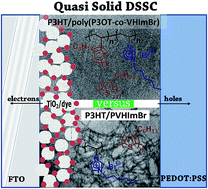
The cells studied in the present work were quasi-solid-state DSSCs with a layer structure obeying the following configuration: (1) a layer of mesoscopic titania sensitized with a standard dye sensitizer; (2) a mixed layer composed of a blend of the hole-transporting polymer P3HT (poly(3-hexylthiophene-2,5-diyl)) with polymeric ionic liquid at various proportions; and (3) a top layer of conductive PEDOT:PSS plus silver conduct electrodes making the counter electrode. Such cells were fabricated as follows. FTO-coated glass substrates were cut in pieces of dimensions 1 cm × 3 cm. One-third of the conductive layer was removed using zinc powder and hydrochloric acid. Then, they were washed with detergent, rinsed with distilled water and subsequently with ethanol in an ultrasonic bath, and finally dried under an air stream. A thin layer of compact titania was first sprayed over the patterned FTO electrode using 0.2 mol L−1 diisopropoxytitanium bis(acetylacetonate) solution in ethanol and then it heated at 500 °C for 1 h. On this thin bottom layer, a titania paste made of P25 nanoparticles was applied by screen printing, using a 90 mesh screen. The film was heated again up to 500 °C for 20 min. Then, the film was treated with a 0.04 mol L−1 aqueous solution of TiCl4 for 30 min at 70 °C, followed by heating up to 500 °C for 20 min. This final titania film was about 10 μm thick, as determined by its profile using SEM. As soon as the final film was taken out of the oven, it was dipped in a 0.5 mmol L−1 N719 solution in ethanol containing 5 mmol L−1 chenodeoxycholic acid and was left overnight. The film was then heavily coloured with the attached dye, then rinsed with ethanol and dried in a N2 stream. The presence of chenodeoxycholic acid is a recent common practice56,57 and it proved beneficial also in the present case. The next step of cell fabrication was the deposition of the mixture of the hole-transporting P3HT with the polymeric ionic liquid. The mixture was prepared by making 20 mg mL−1 solutions in chloroform using various proportions of the two materials. Optimal results were obtained by mixing 18 mg of P3HT with 2 mg of the polymeric ionic liquid. Both homopolymer and copolymer ionic liquids were tried. This layer was deposited by spin-coating at 3000 rpm for 1 min and dried in an oven for 15 min at 100 °C. Then, a layer of PEDOT:PSS was deposited by spin-coating the commercial solution at 1500 rpm, which was annealed in an oven for 15 min at 150 °C. Finally, silver electrodes were painted on the top with a brush using a mask. The electrodes were rapidly annealed (30 s) at 130 °C. Their size was 1 mm × 10 mm.

Results and discussion

Synthesis of the vinyl monomer ILs

The first step of this work was the synthesis of IL polymerizable monomers. We used two different starting materials, 1-vinyl imidazole and 1-methyl imidazole, in order to synthesize two, different types of ionic liquid monomers. As a result, we obtained two monomers, 1-(4-vinylbenzyl)-3-methyl imidazolium tetrafluoroborate (VBMImT)52 (after ion exchange between chloride and tetrafluoroborate) and 1-vinyl-3-hexyl-imidazolium bromide (VHImBr).53

The first part of Schemes 1 and 2 show the synthetic procedures for the preparation of the ionic liquid monomers VBMImT and VHImBr, respectively.


image file: c5ra27374a-s1.tif
Scheme 1 Synthetic procedures for the monomer VBMImT and for the homopolymer PVBMImT.

image file: c5ra27374a-s2.tif
Scheme 2 Synthetic procedures for the monomer VHImBr and for the homopolymer PVHImBr.

The successful formation of the desired monomers was confirmed by 1H NMR (Fig. S1a and S2a) and ESI-MS (Fig. S3). The assignment of the NMR peaks to the monomers' protons show the absence of any by-products. This is also proven by the mass spectra, which show the M+ ion mass, as the ESI-MS instrument was tuned in positive ion mode. In the case of VBMImT, an intense m/z of 117.38 [M+] and 118.39 [M + H+] could be observed, besides the ones at 199.32 [M+] and 200.33 [M + H+] attributed to the product. This peak is due to the fragment that occurs when the methylimidazolium unit is cleaved from VBMImT. IR spectroscopy of the monomers was also carried out, as shown in Fig. S4a and S4b, for the two monomers, respectively, and in comparison to the starting materials in each case. In both ionic liquid monomers, characteristic bands from the presence of the imidazolium unit can be observed. More specifically, the symmetric C[double bond, length as m-dash]C stretching vibration around 1565–1570 cm−1, the aromatic C–H stretch (3050–3100 cm−1), the C[double bond, length as m-dash]N stretch (1630–1650 cm−1), the C–N stretch (1160–1170 cm−1) and the in-plane C–C vibrations of the imidazolium ring (around 1580 cm−1) exist in both products. On the other hand, the VBMImT monomer presents two peaks at 760 cm−1 and 1150 cm−1, respectively, due to the BF4 anion. The VHImBr monomer shows an aliphatic C–H peak around 2850 cm−1, because of the hexyl chain, and a broad peak at 3300–3500 cm−1, due to the hydration of the ionic liquid.58–61

Preparation of the homopolymers and copolymers

For the synthesis of the homopolymers PVBMImT and PVHImBr (as shown in Schemes 1 and 2, respectively), a number of different conditions were tested (Table 1) by varying the monomer to initiator ratio and the solvent used. Successful polymerizations were obtained using the conditions of entries 3, 5 and 6 of Table 1. As can be seen from the data of Table 1, the best results were obtained when MeCN and/or CHCl3 were used as solvents. After purification, the formed homopolymers were characterized via 1H NMR spectroscopy (Fig. S1b and S2b) and via ATR spectroscopy (the respective ATR spectra are given in Fig. 2a and b in comparison to the respective copolymers with vinyl-P3OT, as described below). From the 1H NMR characterization of the homopolymers (Fig. S1b for PVBMImT and Fig. S2b for PVHImBr) compared to their respective monomers (Fig. S1a and S2a, respectively), no monomer residues can be observed, since the vinyl protons (located at 5.2, 5.6 and 6.8 ppm) have disappeared completely and broad peaks are formed proving the polymeric nature of the final purified products.

After the successful formation of the homopolymers, respective copolymers based on the ionic liquid vinyl monomers and vinyl-functionalized dye molecules, either a ω-end vinyl-polythiophene macromonomer (Scheme 3) or a ruthenium complex (Scheme 4) were formed.


image file: c5ra27374a-s3.tif
Scheme 3 Synthesis of polythiophene–ionic liquid random copolymers poly(P3OT-co-VBMImT) and poly(P3OT-co-VHImBr).

image file: c5ra27374a-s4.tif
Scheme 4 Synthesis of the copolymer poly(Ru-co-VBMImT).

For the polythiophene containing copolymers of Scheme 3, their 1H NMR characterization (Fig. 1a and b), using CDCl3, revealed the disappearance of the vinyl groups (located at 5.2, 5.6 and 6.8 ppm), which demonstrates the full conversion of the monomers to the polymers. The conversion of the ionic liquid monomers was further confirmed by ATR spectroscopy (Fig. 2). The existence of a small peak at 2900 cm−1 in PVBMImT but not in VBMImT is due to the conversion of vinyl groups (CH2[double bond, length as m-dash]CH bond) to the polymeric chain (CH2–CH bond). This alternation could not be observed among VHImBr and PVHImBr, because VHImBr bears an alkyl hexyl chain, which absorbs in the same region. After the copolymerization of the IL vinyl monomers with vinyl-P3OT, the specific peak is more intense because of the thiophene's octyl chain. Vibrations from the imidazolium group can be observed at 1040 and 1140 cm−1 due to the C–N bond and near 1550 cm−1 due to C[double bond, length as m-dash]N.59,62 Furthermore, bands appearing in the area 700–900 cm−1 can also be ascribed to contributions from the ring bending modes of the imidazolium cation.63


image file: c5ra27374a-f1.tif
Fig. 1 1H NMR of poly(P3OT-co-VBMImT) (a) and poly(P3OT-co-VHImBr) (b) in CDCl3.

image file: c5ra27374a-f2.tif
Fig. 2 ATR spectra of poly(P3OT-co-VBMImT) (a) and poly(P3OT-co-VHImBr) (b) in comparison to the starting materials and the respective homopolymers.

Efforts were also made for the characterization of the copolymers via GPC. However, due to the ionic nature and the nitrogen-containing heterocycles of the polymeric ionic liquid blocks, the molecular weights were substantially underestimated, leading to even lower molecular weights than the initial vinyl polythiophene macromonomer. In particular, for the poly(P3OT-co-VBMImT) copolymer, an Mn = 6.500 was found, while for the copolymer poly(P3OT-co-VHImBr)], its Mn was in the range of 4.800, both of which are significantly lower than the initial vinyl-P3OT macromonomer's Mn of 21.000.

The polythiophene–ionic liquid copolymers were also characterized by thermogravimetric analysis (TGA). Specifically, as seen in Fig. S5, both copolymers show increased thermal stability when compared to the ionic liquid monomers and homopolymers, and are almost completely degraded around 450 °C (VBMImT and PVBMImT) and 350 °C (VHImBr and PVHImBr). On the other hand, vinyl-P3OT is thermally stable up to 500 °C, leading to copolymers with higher degradation temperatures.

Regarding the optical properties of the synthesized compounds, UV-Vis absorption and PL emission spectra were carried out in solution. Vinyl-P3OT and the corresponding copolymers poly(P3OT-co-VBMImT) and poly(P3OT-co-VHImBr) were dissolved in CHCl3. VHImBr is also soluble in chloroform, in contrast with the other monomeric ionic liquid, VBMImT, for which acetonitrile was used instead. Finally, both homopolymers were dissolved in MeOH. The two copolymers demonstrated similar behaviours in their absorption spectra, presenting a broad peak around 450 nm. As can be seen in Fig. 3, this peak is slightly shifted to a lower wavelength in the copolymers' cases in comparison to the pure vinyl-P3OT. The intense peak at 280 nm in poly(P3OT-co-VBMImT) is attributed to VBMImT and is shifted around 25 nm in comparison to the monomeric VBMImT.


image file: c5ra27374a-f3.tif
Fig. 3 UV-Vis spectra of poly(P3OT-co-VBMImT) (a) and poly(P3OT-co-VHImBr) (b) in comparison to the starting materials and the respective homopolymers.

Fig. 4 shows the PL spectra of the copolymers versus the vinyl-P3OT macromonomer in chloroform solutions, after excitation at the P3OT absorption maximum. The PL spectra of the respective ionic liquid homopolymers are given in the inset of Fig. 4. For both the copolymers, emissions due to the P3OT blocks are detected at 564 nm, which is slightly blue-shifted compared to the net vinyl-P3OT, which emits at 570 nm.


image file: c5ra27374a-f4.tif
Fig. 4 PL spectra of poly(P3OT-co-VBMImT) and poly(P3OT-co-VHImBr) in comparison to vinyl-P3OT after excitation at 450 nm. The inset shows the initial monomers' PL spectra, VBMImT in MeOH and VHImBr in MeCN, after excitation at 220 and 250 nm.

image file: c5ra27374a-f5.tif
Fig. 5 1H NMR of poly(Ru-co-VBMImT) in DMSO-d6.

Scheme 4 presents the copolymerization reaction of the Ru(bpy)2(styrylbpy) monomer55 with the monomeric VBMImT. Since both the ruthenium complex and the monomeric ionic liquid are soluble in acetonitrile, MeCN was used as the polymerization solvent, while the IL/initiator ratio was 11/1 (Table 1).

The structural characterization of the copolymer was carried out using 1H NMR and ATR spectroscopies (Fig. 5 and S6a). Thermogravimetric analysis of poly(Ru-co-VBMImT) showed increased thermal stability in comparison to the ionic liquid monomer and homopolymer (Fig. S6b), which is attributed to the increased thermal stability of the ruthenium complex monomer.

UV-Vis and PL spectroscopies of acetonitrile solutions of the Ru(bpy)2(styrylbpy) and of the copolymer poly(Ru-co-VBMImT) were employed for their optical properties evaluation, as shown in Fig. 6, respectively. In the absorption spectra of the poly(Ru-co-VBMImT), no significant alternation was observed in comparison to the monomer complex Ru(bpy)2(styrylbpy) in the region above 260 nm (Fig. 6a). On the other hand, the copolymer showed an intense peak around 210 nm, which does not exist in the monomeric ruthenium complex, and is attributed to VBMImT. At 320 nm, both the monomeric complex and the copolymer show an absorption due to the π–π* LC (ligand-centered) transitions of 2,2′-bipyridine, and also an absorption at around 450 nm, which is characteristic of the d–π* MLCT (metal to ligand charge transfer) of the Ru(bpy)2(styrylbpy) complexes.55 The photoluminescence examination in solution of both the copolymer poly(Ru-co-VBMImT) and of the monomer complex Ru(bpy)2(styrylbpy) showed a broad peak around 600 nm, after excitation at 450 nm, due to the ruthenium complex's d–π* MLCT absorption band (Fig. 6b).


image file: c5ra27374a-f6.tif
Fig. 6 UV-Vis spectra (a) and PL spectra (b) after excitation at 450 nm of VBMImT, PVBMImT, Ru(bpy)2(styrylbpy) and poly(Ru-co-VBMImT) in MeCN solutions.

Quasi-solid-state DSSC fabrication and testing

Quasi-solid-state DSSCs were constructed in a layer structure using a standard mesoporous titania film sensitized by the most frequently employed Ru-based dye N719. We used P3HT as a hole-collecting and transfer layer and a combination of PEDOT:PSS with silver electrodes as the counter electrode. The novelty of the present work was the introduction of a small quantity of polymeric ionic liquid into the hole-transporting layer. It has been previously reported that the ionic content in the hole-transporting layer may modify its electronic properties and subsequently affect the efficiency of solid-state sensitized solar cells.64–66 This was also verified by the presently studied cells. The term quasi-solid-state DSSC has been used in the present work to underline the fact that the P3HT/polymeric ionic liquid blend should no longer be considered as a purely solid material.

A few different polymeric ionic liquids have been employed and tested in quasi-solid-state DSSC configuration. Fig. 7 and Table 2 show current–voltage data for the studied cells. It must first be underlined that the cells showed an acceptable performance when the polymeric ionic liquid content was relatively low. Thus, optimized data were obtained when the P3HT/polymeric ionic liquid ratio was 9[thin space (1/6-em)]:[thin space (1/6-em)]1 w/w. On the other hand, most polymeric ionic liquids did not show any substantial influence on the cell performance compared to pure P3HT. However, one of the prepared samples demonstrated a marked improvement of cell efficiency. Indeed, as seen in Fig. 7 and Table 2, the introduction of PVHImBr resulted in about a 30% improvement of efficiency. This increase was due to the large increase in the open-circuit voltage of the cell and the improvement of the fill factor, despite the fact that a substantial decrease in the current density was caused by the introduction of the ionic liquid. The decrease in the current was most probably due to the fact that the above cells function by hole collection and transfer through the hole-conducting P3HT. The interference of the ionic agent most probably disrupts some of the hole-transporting channels. On the contrary, the presence of the ionic agent establishes a potential gradient that results in an open-circuit voltage increase. Such a voltage increase was also observed in a previous publication treating a solid-state quantum-dot-sensitized solar cell where a tiny quantity of Na2S was added as an ionic agent.66 Even though the current dropped in the present case, the voltage increase had a marked beneficial effect on cell performance. The advantage of the presently introduced materials is that they can be mixed with P3HT to eliminate solubility problems.


image file: c5ra27374a-f7.tif
Fig. 7 JV curves for solar cells made of photoanodes bearing a nanocrystalline titania film on an FTO electrode sensitized by N719 dye and on the top P3HT mixed with 10% w/w of a polymeric poly ionic liquid: (1) no ionic liquid, (2) P3HT and poly(P3OT-co-VHImBr), (3) P3HT and PVBImT, (4) P3HT and PVHImBr.
Table 2 Current–voltage characteristics of the cells. Data extracted from Fig. 7
Composition of the hole-transporting/ionic liquid layer Voc (V) Jsc (mA cm−2) FF (%) η (%)
1 P3HT alone 0.42 17.0 35 2.5
2 P3HT/poly(P3OT-co-VHImBr) 0.42 7.0 30 0.9
3 P3HT/PVBImT 0.29 11.2 33 1.1
4 P3HT/PVHImBr 0.55 14.1 42 3.2


Morphology characterization of the polymeric materials employed in DSSC testing

Having the results from the DSSC measurements in mind, and in an effort to clarify the unexpected better performance of the net PIL homopolymer versus its copolymer with P3HT, we proceeded with the morphology evaluation of the blends as those that were prepared and tested in the DSSC devices. The transmission electron microscopy (TEM) images of the net P3HT, the 9[thin space (1/6-em)]:[thin space (1/6-em)]1 blend of P3HT/poly(P3OT-co-VHImBr) and the 9[thin space (1/6-em)]:[thin space (1/6-em)]1 blend of P3HT/PVHImBr, all casted from dilute CHCl3 solutions, are presented in Fig. 8 below.
image file: c5ra27374a-f8.tif
Fig. 8 TEM images of (a) P3HT at scale bar 200 = nm (inset scale bar = 50 nm) (b) P3HT/poly(P3OT-co-VHImBr) 9[thin space (1/6-em)]:[thin space (1/6-em)]1 at scale bar = 100 nm (inset scale bar = 50 nm) and (c) P3HT/PVHImBr 9[thin space (1/6-em)]:[thin space (1/6-em)]1 at scale bar = 200 nm (inset scale bar = 20 nm).

As can be seen in Fig. 8a, the net P3HT formed uniform films that presented some degree of organization into fibrillary structures due to the close packing and crystallization of the high molecular weight P3HT.1 The casting procedure for the preparation of the TEM samples, of course, does not allow ordering to a great extent, but the method for preparing the P3HT film on the DSSC device, which is accompanied by thermal treatment, should have a more prominent effect on the crystallization of the P3HT macromolecular chains.

On the contrary, the 9[thin space (1/6-em)]:[thin space (1/6-em)]1 blend of P3HT/poly(P3OT-co-VHImBr) shown in Fig. 8b did not present any fibrillar morphological features. The insertion of even a small percentage of the poly(P3OT-co-VHImBr) copolymer to the P3HT matrix obviously led to the compatibilization of the P3HT and the PIL fractions and, moreover, suppressed the crystallization ability of the net P3HT.

Surprisingly, the P3HT/PVHImBr 9[thin space (1/6-em)]:[thin space (1/6-em)]1 blend (see Fig. 8c) presented the same crystallization tendency of the net P3HT (see Fig. 8a), while some darker regions were observed. When looking deeper into those darker regions, we noticed that they consisted of dark spots of about 2 nm and up to 6 nm diameter (inset of Fig. 8c). These higher contrast spots were attributed to the charged imidazolium cation and Br anion of the PVHImBr ionic liquid homopolymer and, more specifically, to the high contrast of the Br atoms under the electron beam.67 Therefore, it can be concluded that the presence of the homopolymer PVHImBr did not disturb the crystallization and ordering of the P3HT and that it was quite uniformly dispersed in selective regions along the polythiophene matrix.

The abovementioned findings constitute an explanation of the better DSSC device performance of the P3HT/PVHImBr blend over the P3HT/poly(P3OT-co-VHImBr) blend, since for P3HT it is known that charge transport is promoted along its crystalline domains, which are interconnected with amorphous regions.1,68 Thus, the net P3HT and the P3HT/PVHImBr blend worked nicely in the DSSC devices, whereas the P3HT/poly(P3OT-co-VHImBr) blend with no ordering into crystalline species did not show an analogous DSSC performance.

Conclusions

Polymeric ionic liquids based on the imidazole moiety and their respective copolymeric ionic liquids using ω-end vinyl rr-poly(3-octyl thiophene) or (vinylphenyl-bipyridine)-Ru(II)-di(bipyridine) were prepared in this present study. Aiming at materials that could eventually be employed in quasi-solid-state DSSC, we prepared these ionic liquid polymers and copolymers to aid the ionic character of the hole-transporting layer of the cell.

The homopolymer PILs and copolymer PILs with the thiophene- or ruthenium-based dyes were prepared via radical polymerizations. Their adequate solubility in common organic solvents allows their processability and introduction as an additive of the net organic hole-transporting layer of the cell. Although further improvements are, of course, necessary to increase the efficiency of the solid-state DSSCs, the methodology reported herein shows a promising route for the enhancement of the cells performance. Perhaps the most important finding of the present study is that the presence of the PIL fraction into the hole-transporting P3HT layer improves the device performance as long as it does not disturb the development of crystalline domains that promote the necessary charge carrier transport.

Acknowledgements

This research has been co-financed by the European Union (European Social Fund – ESF) and Greek national funds through the Operational Program “Education and Lifelong Learning” of the National Strategic Reference Framework (NSRF)-Research Funding Program: THALES. Investing in knowledge society through the European Social Fund. Project title: “Innovative materials for nanocrystalline solar cells” (MIS: 377756).

References

  1. G. Dennler, M. C. Scharber and C. J. Brabec, Adv. Mater., 2009, 21, 1323–1338,  DOI:10.1002/adma.200801283.
  2. B. O'Regan and M. Grätzel, Nature, 1991, 353, 737–740,  DOI:10.1038/353737a0.
  3. J. Boucle and J. Ackermann, Polym. Int., 2012, 61, 355–373,  DOI:10.1002/pi.3157.
  4. J. Qu and C. Lai, J. Nanomater., 2013, 2013, 762730,  DOI:10.1155/2013/762730.
  5. H. C. Weerasinghe, F. Huang and Y.-B. Cheng, Nano Energy, 2013, 2, 174–189,  DOI:10.1016/j.nanoen.2012.10.004.
  6. W. Mai, Z. Chai, J. Gu, J. Khan, Y. Yuan, L. Du, X. Yu and M. Wu, RSC Adv., 2015, 5, 88052–88058,  10.1039/c5ra17294b.
  7. Q. Zhang, C. S. Dandeneau, X. Zhou and G. Cao, Adv. Mater., 2009, 21, 4087–4108,  DOI:10.1002/adma.200803827.
  8. A. L. Briseno, T. W. Holcombe, A. I. Boukai, E. C. Garnett, S. W. Shelton, J. J. M. Frechet and P. Yang, Nano Lett., 2010, 10, 334–340,  DOI:10.1021/nl9036752.
  9. P. Giannopoulos, A. Nikolakopoulou, A. K. Andreopoulou, L. Sygellou, J. K. Kallitsis and P. Lianos, J. Mater. Chem A, 2014, 2, 20748–20759,  10.1039/c4ta04515g.
  10. P. Giannopoulos, C. Anastasopoulos, A. K. Andreopoulou and J. K. Kallitsis, J. Surface Interfac. Mater., 2014, 2, 274–279,  DOI:10.1166/jsim.2014.1061.
  11. X. Chen, Q. Tang, B. He and H. Chen, RSC Adv., 2015, 5, 43402–43407,  10.1039/c5ra05078b.
  12. H. M. Upadhyaya, S. Senthilarasu, M.-H. Hsu and D. K. Kumar, Sol. Energy Mater. Sol. Cells, 2013, 119, 291–295,  DOI:10.1016/j.solmat.2013.08.031.
  13. K. Saranya, M. Rameez and A. Subramania, Eur. Polym. J., 2015, 66, 207–227,  DOI:10.1016/j.eurpolymj.2015.01.049.
  14. E. Stathatos, P. Lianos, S. M. Zakeeruddin, P. Liska and M. Grätzel, Chem. Mater., 2003, 15, 1825–1829,  DOI:10.1021/cm0213568.
  15. J. M. Pringle and V. Armel, Int. Rev. Phys. Chem., 2012, 30, 371–407,  DOI:10.1080/0144235X.2011.638450.
  16. J. Wu, Z. Lan, J. Lin, M. Huang, Y. Huang, L. Fan and G. Luo, Chem. Rev., 2015, 115, 2136–2173,  DOI:10.1021/cr400675m.
  17. S. Venkatesan, S.-C. Su, W.-N. Hung, I.-P. Liu, H. Teng and Y.-L. Lee, J. Power Sources, 2015, 298, 385–390,  DOI:10.1016/j.jpowsour.2015.07.062.
  18. M. M. Rashad, A. E. Shalan, M. M. Moharam, A. M. Elseman, M. Rasly and M. Lira-Cantu, RSC Adv., 2015, 5, 103095–103104,  10.1039/c5ra21822e.
  19. A. Sacco, F. Bella, S. De La Pierre, M. Castellino, S. Bianco, R. Bongiovanni and C. F. Pirri, ChemPhysChem, 2015, 16, 960–969,  DOI:10.1002/cphc.201402891.
  20. F. Bella, A. Chiappone, J. R. Nair, G. Meligrana and C. Gerbaldi, Chemical Engineering Transactions, 2014, 41, 211–216,  DOI:10.3303/cet1441036.
  21. M. Gorlov and L. Kloo, Dalton Trans., 2008, 20, 2655–2666,  10.1039/b716419j.
  22. S. M. Zakeeruddin and M. Grätzel, Adv. Funct. Mater., 2009, 19, 2187–2202,  DOI:10.1002/adfm.200900390.
  23. M. Y. A. Rahman, A. Ahmad, A. A. Umar, R. Taslim, M. S. Suait and M. M. Salleh, Ionics, 2014, 20, 1201–1205,  DOI:10.1007/s11581-014-1211-3.
  24. C.-P. Lee, T.-C. Chu, L.-Y. Chang, J.-J. Lin and K.-C. Ho, Solid-State Ionic Liquid Based Electrolytes for Dye-Sensitized Solar Cells, Ionic Liquids – New Aspects for the Future, ed. J. Kadokawa, InTech, 2013, ISBN: 978-953-51-0937-2,  DOI:10.5772/53647.
  25. A. Apostolopoulou, A. Margalias and E. Stathatos, RSC Adv., 2015, 5, 58307–58315,  10.1039/c5ra08744a.
  26. M. Armand, F. Endres, D. R. MacFarlane, H. Ohno and B. Scrosati, Nat. Mater., 2009, 8, 621–629,  DOI:10.1038/nmat2448.
  27. J. V. Zamory, M. Bedu, S. Fantini, S. Passerini and E. Paillard, J. Power Sources, 2013, 240, 745–752,  DOI:10.1016/j.jpowsour.2013.04.127.
  28. J. Lu, F. Yan and J. Texter, Prog. Polym. Sci., 2009, 34, 431–448,  DOI:10.1016/j.progpolymsci.2008.12.001.
  29. H. Zhang, K. Hong and J. W. Mays, Macromolecules, 2002, 35, 5738–5741,  DOI:10.1021/ma025518x.
  30. T. Biedron and P. Kubisa, Polym. Int., 2003, 52, 1584–1588,  DOI:10.1002/pi.1343.
  31. S. Ding, M. Radosz and Y. Shen, Macromolecules, 2005, 38, 5921–5928,  DOI:10.1021/ma050093a.
  32. G. H. Lane, P. M. Bayley, B. R. Clare, A. S. Best, D. R. MacFarlane, M. Forsyth and A. F. Hollenkamp, J. Phys. Chem. C, 2010, 114, 21775–21785,  DOI:10.1021/jp1054809.
  33. A. Lewandowski and A. Swiderska-Mocek, J. Power Sources, 2009, 194, 601–609,  DOI:10.1016/j.jpowsour.2009.06.089.
  34. E. Paillard, Q. Zhou, W. A. Henderson, G. B. Appetecchi, M. Montanino and S. Passerini, J. Electrochem. Soc., 2009, 156, A891–A895,  DOI:10.1149/1.3208048.
  35. R. D. Costa, E. Orti, H. J. Bolink, S. Graber, C. E. Housecroft and E. C. Constable, Adv. Funct. Mater., 2010, 20, 1511–1520,  DOI:10.1002/adfm.201000043.
  36. A. Balducci, W. A. Henderson, M. Mastragostino, S. Passerini, P. Simon and F. Soavi, Electrochim. Acta, 2005, 50, 2233–2237,  DOI:10.1016/j.electacta.2004.10.006.
  37. P. Wang, S. M. Zakeeruddin, I. Exnar and M. Grätzel, Chem. Commun., 2002, 8, 2972–2973,  10.1039/b209322g.
  38. W. Kubo, S. Kambe, S. Nakade, T. Kitamura, K. Hanabusa, Y. Wada and S. Yanagida, J. Phys. Chem. B, 2003, 107, 4374–4381,  DOI:10.1021/jp034248x.
  39. D. Xu, H. Zhang, X. Chen and F. Yan, J. Mater. Chem. A, 2013, 1, 11933–11941,  10.1039/c3ta12031g.
  40. H. M. Ng, S. Ramesh and K. Ramesh, Electrochim. Acta, 2015, 175, 169–175,  DOI:10.1016/j.electacta.2015.01.076.
  41. L. Chang, C. Lee, C. Li, M. Yeh, K. Ho and J. Lin, J. Mater. Chem. A, 2014, 2, 20814–20822,  10.1039/c4ta05436a.
  42. H. Tang, S. Ding, Y. Shen and M. Radosz, J. Polym. Sci., Part A: Polym. Chem., 2004, 42, 5794–5801,  DOI:10.1002/pola.20423.
  43. B. Lin, T. Feng, F. Chu, S. Zhang, N. Yuan, G. Qiao and J. Ding, RSC Adv., 2015, 5, 57216–57222,  10.1039/c5ra10702d.
  44. P. Wang, B. Wenger, R. Humphry-Baker, J.-E. Moser, J. Teuscher, W. Kantlehner, J. Mezger, E. V. Stoyanov, S. M. Zakeeruddin and M. Grätzel, J. Am. Chem. Soc., 2005, 127, 6850–7685,  DOI:10.1021/ja042232u.
  45. D. Kuang, P. Wang, S. Ito, S. M. Zakeeruddin and M. Grätzel, J. Am. Chem. Soc., 2006, 128, 7732–7733,  DOI:10.1021/ja061714y.
  46. X. Chen, Q. Li, J. Zhao, L. Qiu, Y. Zhang, B. Sun and F. Yan, J. Power Sources, 2012, 207, 216–221,  DOI:10.1016/j.jpowsour.2012.01.143.
  47. J.-G. Chen, R. Vittal, M.-H. Yeh, C.-Y. Chen, C.-G. Wu and K.-C. Ho, Electrochim. Acta, 2014, 130, 587–593,  DOI:10.1016/j.electacta.2014.03.061.
  48. O. Fontaine, A. Touidjine, M. Maréchal, C. Bonhomme, F. Ribot, B. Geffroy, B. Jousselme, C. Sanchez and C. Laberty-Robert, New J. Chem., 2014, 38, 2008–2015,  10.1039/c3nj01272g.
  49. M. S. Su'ait, M. Y. A. Rahman and A. Ahmad, Solar Energy, 2015, 115, 452–470,  DOI:10.1016/j.solener.2015.02.043.
  50. M. Yoshizawa, W. Ogihara and H. Ohno, Polym. Adv. Technol., 2002, 13, 589–594,  DOI:10.1002/pat.261.
  51. Y. Han, J. M. Pringle and Y.-B. Cheng, Photochem. Photobiol., 2015, 91, 315–322,  DOI:10.1111/php.12399.
  52. W. S. Chi, J. K. Koh, S. H. Ahn, J.-S. Shin, H. Ahn, D. Y. Ryu and J. H. Kim, Electrochem. Commun., 2011, 13, 1349–1352,  DOI:10.1016/j.elecom.2011.08.005.
  53. R. Marcilla, J. A. Blazquez, J. Rodriguez, J. A. Pomposo and D. Mecerreyes, J. Polym. Sci., Part A: Polym. Chem., 2004, 42, 208–212,  DOI:10.1002/pola.11015.
  54. R. S. Loewe, P. C. Ewbank, J. Liu, L. Zhai and R. D. McCullough, Macromolecules, 2001, 34, 4324–4333,  DOI:10.1021/ma001677.
  55. E. K. Pefkianakis, N. P. Tzanetos and J. K. Kallitsis, Chem. Mater., 2008, 20, 6254–6262,  DOI:10.1021/cm800911y.
  56. D. Joly, L. Pelleja, S. Narbey, F. Oswald, J. Chiron, J. N. Clifford, E. Palomares and R. Demadrille, Sci. Rep., 2014, 4(4033), 1–7,  DOI:10.1038/srep04033.
  57. C. V. Kumar, D. Raptis, E. N. Koukaras, L. Sygellou and P. Lianos, Org. Electron., 2015, 25, 66–73,  DOI:10.1016/j.orgel.2015.06.009.
  58. Y. Jeon, J. Sung, C. Seo, H. Lim, H. Cheong, M. Kang, B. Moon, Y. Ouchi and D. Kim, J. Phys. Chem. B, 2008, 112, 4735–4740,  DOI:10.1021/jp7120752.
  59. T. Moumene, E. H. Belarbi, B. Haddad, D. Villemin, O. Abbas, B. Khelifa and S. Bresson, J. Mol. Struct., 2015, 1083, 179–186,  DOI:10.1016/j.molstruc.2014.11.061.
  60. S. J. L. P. Perez and S. D. Arco, J. Chin. Chem. Soc., 2014, 61, 935–939,  DOI:10.1002/jccs.201300555.
  61. F. Shi and Y. Deng, Spectrochim. Acta, Part A, 2005, 62, 239–244,  DOI:10.1016/j.saa.2004.12.031.
  62. K. Malek, A. Puc, G. Schroeder, V. I. Rybachenko and L. M. Proniewicz, Chem. Phys., 2006, 327, 439–451,  DOI:10.1016/j.chemphys.2006.05.021.
  63. K. Noack, P. S. Schulz, N. Paape, J. Kiefer, P. Wasserscheid and A. Leipertz, Phys. Chem. Chem. Phys., 2010, 12, 14153–14161,  10.1039/c0cp00486c.
  64. R. Zhu, C.-Y. Jiang, B. Liu and S. Ramakrishna, Adv. Mater., 2009, 21, 994–1000,  DOI:10.1002/adma.200802388.
  65. N. Balis, V. Dracopoulos, M. Antoniadou and P. Lianos, J. Photochem. Photobiol., A, 2010, 214, 69–73,  DOI:10.1016/j.jphotochem.2010.06.010.
  66. G. Sfyri, S. Sfaelou, K. S. Andrikopoulos, N. Balis, G. A. Voyiatzis and P. Lianos, J. Phys. Chem. C, 2014, 118, 16547–16551,  DOI:10.1021/jp412134m.
  67. M. Koebe, M. Drechsler, J. Weber and J. Yuan, Macromol. Rapid Commun., 2012, 33, 646–651,  DOI:10.1002/marc.201100836.
  68. V. D. Mihailetchi, H. Xie, B. de Boer, L. M. Popescu, J. C. Hummelen, P. W. M. Blom and L. J. A. Koster, Appl. Phys. Lett., 2006, 89, 012107,  DOI:10.1063/1.2212058.

Footnote

Electronic supplementary information (ESI) available. See DOI: 10.1039/c5ra27374a

This journal is © The Royal Society of Chemistry 2016