
Gold nanoparticle incorporation into nanoporous anatase TiO2 mesocrystal using a simple deposition–precipitation method for photocatalytic applications
Tiehu Han,
Huigang Wang* and
Xuming Zheng*
Department of Chemistry, Engineering Research Center for Eco-dyeing and Finishing of Textiles, MOE and Zhejiang Provincial Top Key Academic Discipline of Chemical Engineering and Technology, Zhejiang Sci-Tech University, Hangzhou 310018, China. E-mail: zdwhg@163.com; huigwang@uni-osnabrueck.de; Tel: +86-571-8684-3627
First published on 5th January 2016
Abstract
Spindle-shaped nanoporous anatase TiO2 mesocrystals with exposed active {101} facets have been successfully prepared through a hydrothermal method with tetrabutyl titanate as the precursor. By a deposition–precipitation process, highly dispersed Au nanoparticles loaded on spindle-shaped mesoTiO2 exposed {101} facets, denoted as Aux/mesoTiO2, were firstly fabricated to establish close Schottky junctions to improve the visible light activity and the stability of Au on the catalyst surface. The photodegradation of methylene blue (MB) over Aux/mesoTiO2 was systematically investigated. The exposed active {101} facets together with the loaded Au nanoparticles dramatically enhanced the visible light photocatalytic activity of TiO2. The synergistic effect of the high intrinsic single-crystal-like nature of the anatase phase, the stability of gold and the strong interaction between Au and mesoTiO2 result in extraordinary photocatalytic stability of the catalyst. The detailed e− and h+ separation dynamics for the visible-light and UV-vis induced catalytic mechanisms were discussed.
1. Introduction
In response to increasing environmental and energy related concerns, photocatalysis using sunlight has been attracting tremendous attention.1,2 Among these photocatalysts, titania (TiO2) has proven to be the most widely used photocatalyst in applications such as environmental cleaning and hydrogen energy.3,4 However, TiO2 is far from being a perfect photocatalyst, due to its wide band gap, which limits its photo-absorption to the UV region (about 5% of solar light). In order to extend the photoresponse from the UV region to the visible light region, great efforts have been made to modify TiO2, such as doping,5,6 metal deposition,7–9 surface sensitization10–12 and coupling of composite semiconductors.13–15As a novel class of TiO2 material, TiO2 mesocrystal has received rapidly increasing attention since anatase TiO2 mesocrystals (mesoTiO2) were first prepared by topotactic conversion from NH4TiOF3 mesocrystals in the presence of nonionic surfactants.16,17 Bian and co-workers reported that mesoTiO2 superstructures had significantly enhanced charge separation upon UV-light irradiation due to their remarkably long-lived charges.18 Hong and co-workers reported an experimental study of a new synthesis strategy for the formation of unique rutile TiO2 mesocrystals constructed from ultrathin nanowires in the absence of an additive. The rutile TiO2 mesocrystals were used for the first time as an electrode in LIBs and exhibited a large reversible lithium-ion charge–discharge capacity and excellent cyclic stability.19 However, the practical application of mesocrystals remains a great challenge, because their formation processes are poorly understood.
Recently, Au/TiO2, the representative “plasmonic photocatalyst”, has attracted much interest as a new type of visible light photocatalyst.20–23 Gold is a noble metal and does not undergo corrosion under photocatalytic conditions. In the photocatalytic process, the noble metal plays an important role: on one hand, due to surface plasmon resonance (SPR), gold nanoparticles (NPs) possess unique absorption in the whole visible region, which can be utilized to harvest visible light;20–23 on the other hand, the formation of a Schottky barrier between TiO2 and Au NPs inhibits the e–h pair recombination process.24 The photocatalytic reaction of Au/TiO2 mainly occurs on the surface of TiO2. The TiO2 surface can transfer the electrons from its conduction band (CB) to Au8 or accept the electrons from Au;25,26 this depends on whether the excitation occurs on TiO2 or on the surface plasmon band of Au.25,27 This obviously raises questions regarding the photocatalytic activity of mesoTiO2 loaded with Au NPs under visible light irradiation. However, the incorporation of plasmonic Au NPs onto mesoTiO2 has not been reported.
In this study, a simple deposition–precipitation (DP) method28,29 was used to deposit Au NPs on mesoTiO2 which was synthesized through a solvothermal method using tetrabutyl titanate (TBT) as the titanium source and acetic acid as the solvent.30,31 The photocatalytic activity of the Au/mesoTiO2 samples under simultaneous UV and visible light irradiation or visible light irradiation alone was evaluated by their capability to degrade methylene blue (MB). Furthermore, we also carefully investigated the influences of Au content on the microstructures and photocatalytic activity of the mesoTiO2 samples. It was found that superstructure-based Au/mesoTiO2 with suitable gold content has significantly enhanced photocatalytic activity.
2. Experimental section
2.1 Synthesis of spindle-shaped nanoporous anatase TiO2 mesocrystals
Spindle-shaped nanoporous anatase TiO2 mesocrystals were synthesized by the solvothermal reaction of TBT–HAc solution. In a typical synthesis, 1 mL of TBT was added dropwise to 50 mL of HAc with continuous stirring. The obtained white suspension was transferred to a dried Teflon autoclave with a capacity of 100 mL, and then maintained at 200 °C for 24 h. After being cooled to room temperature, the product was collected by high-speed centrifugation, washed with ethanol several times, dried at 60 °C overnight, and finally calcined at 400 °C for 30 min to remove residual organics.2.2 Synthesis of Au/mesoTiO2
The Au/mesoTiO2 catalysts were prepared by a deposition–precipitation (DP) method. In the standard preparation conditions, 100 mL of an appropriate concentration of hydrogen tetrachloroaurate(III) trihydrate (HAuCl4·3H2O, Alfa Aesar, 99.99%) was heated to 80 °C. 1 g of TiO2 was dispersed in the solution, and the pH was readjusted to 8.0 with NaOH (1 M). The suspension was then stirred for another 4 h at 80 °C. After being cooled to room temperature, the product was centrifuged, washed and dried. Finally, the sample was calcined at 300 °C for 4 h to obtain Aux/mesoTiO2, where x is the amount (in wt%) of Au loaded [x% = Au/(Au + mesoTiO2) × 100%].2.3 Characterization
Crystalline phases of the prepared samples were characterized by X-ray diffraction (XRD) on a DX-2700 diffractometer (Dandong Hanyuan Instrument Co. Ltd, China) using Cu Ka radiation (λ = 0.15418 nm). Transmission electron microscope (TEM) images were taken on a JEOL-2100 electron microscope operating at an accelerating voltage of 200 kV. The morphology of the materials was analyzed using a Hitachi S-4800 field emission scanning electron microscope (FE-SEM). UV-vis diffuse-reflectance spectroscopy (DRS) was performed with a Shimadzu UV-2450 spectrophotometer using BaSO4 as the reference. The specific surface area of the sample was deduced by the BET method (N2 adsorption) with a Micromeritics ASAP 2020 system. X-ray photoelectron spectroscopy (XPS) was performed on a Kratos AXIS Ultra DLD instrument with an AL Ka monochromatic source. All binding energies were referenced to the C1s peak (284.6 eV) arising from adventitious hydrocarbons. The 488 nm Raman measurements were carried out with a quartz cell using an experimental apparatus consisting of a triple monochromator (TriVista TR557, Princeton Instruments) equipped with an argon ion laser (Coherent, CVI MELLES GRIOT) as a source of exciting light at 488 nm (20 mW on the sample) and with a liquid-nitrogen-cooled charge coupled device (CCD) array (Princeton Instruments Inc.; model ID: LN/2048 x 512, B/I, UVAR), allowing a wavenumber coverage of 1089 cm−1 within the chip active area and a spectral resolution (the instrumental apparatus function, full width at half maxima) of 2.5 cm−1.2.4 Photocatalysis experiments
The photocatalytic activities of the materials were examined by degrading methylene blue (MB) in aqueous solution under visible light irradiation using a 300 W xenon lamp (CEL-HXUV300, Beijing CEAULIGHT) with a 400 nm cutoff filter as the light source. In each experiment, a total of 50 mg of catalyst was added to a 100 mL solution of 10 mg L−1 MB in a 120 mL quartz reactor with a circulating water system to maintain a constant temperature, and the distance between the light and the surface of the solution was set at about 10 cm. Before irradiation, the suspension was stirred in the dark for 30 min to establish the adsorption–desorption equilibrium of the solution. After the start of the photocatalytic reaction, approximately 4 mL of the mixture was taken at regular time intervals, and then centrifuged to separate the photocatalyst particles. The concentration was analyzed by measuring the maximum absorbance at 665 nm for MB using a UV-vis spectrometer (Varian Cary 50).3. Results and discussion
Fig. 1a and b shows representative FE-SEM images of the synthesized mesoTiO2. An overview image at low magnification (see Fig. 1a) illustrates that a large quantity of particles have formed with uniform spindle shape and unique size. The lengths and diameters were mostly found to be 300 to 400 nm and 200 to 300 nm, respectively. The high-magnification SEM image shown in Fig. 1b reveals that the spindle-shaped particles are composed of primary nanoparticles, which form a rough and porous surface. The latter was subsequently confirmed by pore analysis based on N2 adsorption measurements (discussed below). The TEM image in Fig. 1c shows the unique mesoTiO2, confirming that the particle consists of nanosized subunits. Both the HTTEM image (Fig. 1d) and the selective area electron diffraction (SAED, inset of Fig. 1d) show well resolved {101} lattice fringes (distance 0.352 nm) and diffraction cycles indicative of a highly crystalline TiO2 anatase framework. The dominant exposed face of the spindle-shaped nanoporous anatase TiO2 mesocrystals is {101}. These exposed {101} facets were taken as an ideal support for highly dispersed Au nanoparticles to improve the stability of Au and the visible light activity. It is clear to see that the diffraction spots are slightly elongated, indicating that a mesocrystal structure was formed.19,32 Fig. 1e shows a typical SEM image of Au5.0/mesoTiO2. Well dispersed Au nanoparticles (bright dots) can be discerned from the background. It is evident that the DP process has affected the morphology and size of mesoTiO2 in this study. The TEM image of an individual particle of Au5.0/mesoTiO2 (Fig. 1f) indicates that the Au NPs are nearly spherical, with an average size of about 8 nm. Additional XPS results confirmed that the deposited Au NPs were metallic Au(0) in the Au/mesoTiO2 samples (discussed below). | ||
| Fig. 1 FE-SEM images (a and b) and TEM image (c) of mesoTiO2. HRTEM image of mesoTiO2 (d) and selective area electron diffraction (SAED, inset d). FE-SEM and TEM images of Au5.0/mesoTiO2 (e and f). | ||
To investigate the surface composition and the chemical states of the elements in as-prepared Au/mesoTiO2, XPS studies were conducted for mesoTiO2 before and after Au loading. As shown in Fig. 2a, the wide-scan survey spectra of mesoTiO2 and Au/mesoTiO2 all contain O, Ti and C elements; the emergence of the C element can be attributed to residual carbon from the sample and adventitious hydrocarbon from the XPS instrument itself. The inset in (a) shows a comparison between the spectra of mesoTiO2 and Au/mesoTiO2 in the range of 0 to 100 eV; obviously, there are some weak peaks in the range of 80 to 100 eV for Au/mesoTiO2 which can be ascribed to Au4f. The Au4f core level spectrum, shown in Fig. 2b, is composed of two peaks at the binding energies of 83.3 and 87.2 eV, assigned to Au4f7/2 and Au4f5/2, respectively; these are in good agreement with the reported values of Au(0), suggesting that the Au species is present in the metallic state.33 However, the peak of Au (4f7/2) shifted slightly lower relative to that of free metallic Au(0) (∼83.8 eV). This difference indicates significant charge transfer from TiO2 to Au and thus confirms the strong Au/TiO2 interaction.24 A Schottky barrier is created between Au(0) and mesoTiO2. Furthermore, XPS was used to distinguish the surface change of mesoTiO2 before and after Au loading. Fig. 2c displays the XPS spectra of Ti2p of mesoTiO2 and Au/mesoTiO2; the binding energies of Ti2p3/2 and Ti2p1/2 are equal to 458.6 eV and 464.4 eV, respectively, suggesting the presence of Ti(IV) species.34 By comparison, there are no measurable changes in the peak positions for Ti2p in mesoTiO2 before and after Au loading. Meanwhile, the XPS spectra of O1s (Fig. 2d) shifts from 529.88 to 529.94 eV after Au NPs deposition, owing to the generation of surface oxygen vacancies.35
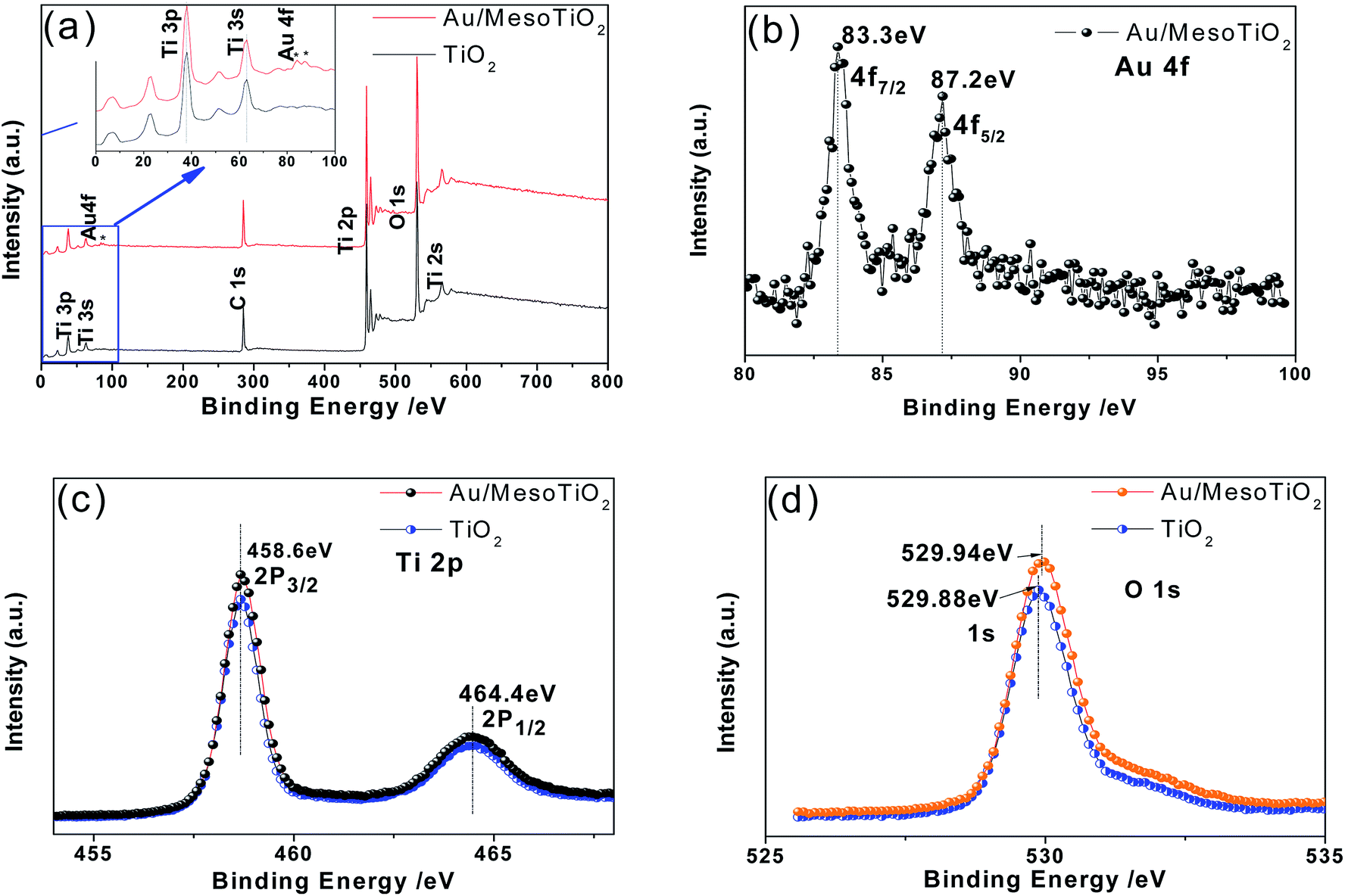 | ||
| Fig. 2 (a) Wide-scan XPS survey spectra of mesoTiO2 before and after Au loading. (b) Au4f XPS spectra of Au5.0/mesoTiO2. The inset of (a) is the corresponding amplification image of (a). High-resolution XPS spectra of (c) Ti2p and (d) O1s for mesoTiO2 before and after Au loading. | ||
Several parameters influence the photocatalytic activity of plasmonic composite Au/mesoTiO2 photocatalysts, including gold particle size, morphology, and amount, as well as the interfacial contact between Au and titania. By adding an appropriate concentration of HAuCl4·3H2O (see Table 1), Au/mesoTiO2 photocatalysts with different weight percentages (wt%) of Au on mesoTiO2 were prepared using the DP method. The dominant exposed face of the spindle-shaped nanoporous anatase TiO2 mesocrystals is {101}, and the Au NPs do not change the anatase phase of mesoTiO2. Therefore, the dominant interfacial contact occurred between the Au nanoparticles and the {101} phase for all samples. Thus, the Au amount has a significant influence on the photocatalytic activity in this study.
| Sample | C (HAuCl4·3H2O) (mM) | Phasea | SBETb (m2 g−1) | Dpc (nm) |
|---|---|---|---|---|
| a A: anatase, R: rutile.b BET surface.c Pore diameter. | ||||
| MesoTiO2 | 0 | A | 73.7 | 6.9 |
| Au1.0/mesoTiO2 | 0.51 | A | 51.8 | 6.8 |
| Au3.0/mesoTiO2 | 1.57 | A | 50.3 | 7.0 |
| Au5.0/mesoTiO2 | 2.67 | A | 68.3 | 7.2 |
| Au7.6/mesoTiO2 | 4.19 | A | 59.2 | 7.3 |
| P25 | 0 | A and R | 57 | — |
| Au3.0/P25 | 1.57 | A and R | 54 | 7.5 |
XRD was used to identify the phase structures of the synthesized samples. Fig. 3 shows the X-ray diffraction patterns of pure mesoTiO2 and Au/mesoTiO2, in which all diffraction peaks of the calcined materials (with or without gold incorporation) can be indexed as anatase TiO2 with standard values in agreement with JCPDS card no. 21-1272. Oddly, no crystalline Au diffraction peaks were observed in any of the Au/mesoTiO2 composites. This may be ascribed to the fact that the gold is highly dispersed in the mesoTiO2 porous structures, and the low loading quantity of Au is beyond the XRD detection limit.36 It should be noted that single crystalline phase Au can be formed through this method.
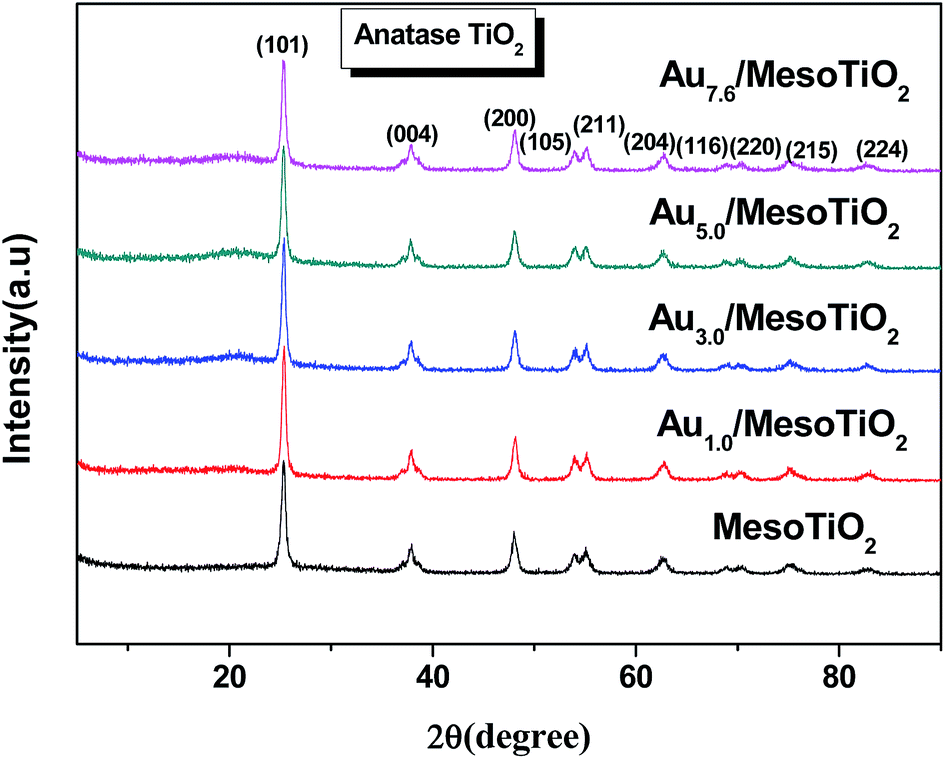 | ||
| Fig. 3 XRD patterns of mesoTiO2 and Au/mesoTiO2 with various Au loadings. | ||
To further identify the phases and the crystallinity of the samples, Raman studies were performed in the range of 100 to 1000 cm−1 (shown in Fig. 4). The Raman peaks at 143.3, 394, 513, and 636 cm−1 can be assigned to the Raman-active modes of anatase with Eg, B1g, A1g, and Eg symmetries, respectively.37 It is interesting to observe that the Eg peak at 143.3 cm−1 gradually shifted to a higher wavenumber as the Au content increased; however, the Eg peak at 636 cm−1 shifted to the opposite direction. This indicates that there was an interaction between the Au and mesoTiO2, and the created crystalline defects within the mesoTiO2 increase with increasing Au content.38 The crystalline defects affect the characteristic vibrational frequency of the anatase TiO2; it can act as a trap to capture photoelectrons, which makes a contribution to inhibiting the charge recombination. Thus, the XRD and Raman characterization of mesoTiO2 and Au/mesoTiO2 demonstrate the high crystallinity of the titania materials and the presence of anatase phase.
 | ||
| Fig. 4 Raman spectra of mesoTiO2 and Au/mesoTiO2 with various Au loadings. | ||
The light absorption properties of the composites were studied by UV-vis spectroscopy, and the effect of Au loading content on the UV-vis absorption properties are revealed in Fig. 5. This figure shows that the absorption of blank mesoTiO2 is only located in the ultraviolet (UV) region below 370 nm, whereas Au/mesoTiO2 shows two absorption bands, with the largest absorption edge located near 370 nm and the second near 558 nm. The presence of two absorption bands indicates two step transitions in the band gap. The pronounced low-energy absorption band at 558 nm is in good agreement with the reported values for Au nanoparticles and may be ascribed to the typical surface plasmon resonance (SPR) of Au NPs.25,39,40
 | ||
| Fig. 5 UV-vis absorption spectra of mesoTiO2 and Au/mesoTiO2 with various Au loadings. | ||
It is clear that with the increase of Au content from 1.0 wt% to 7.6 wt%, the plasmon band intensity of Au/mesoTiO2 increased accordingly, while the light absorption of Au/mesoTiO2 in the UV region is the same as that of mesoTiO2 without Au. The UV-vis spectroscopy results indicate that Au/mesoTiO2 has significantly enhanced visible light absorption and can be photoexcited by visible light irradiation, by which electron–hole pairs can be generated; also, the two step-transition guarantees the prolonged separation lifetime of the electron–hole pairs, and thus, improved photoexcited performance can be expected.
It is known that the peak position and shape of the SPR absorption band are sensitive to Au particle size and morphology.41 In Fig. 5, no red-shifting phenomenon is observed, suggesting that all the Au/mesoTiO2 catalysts have similar Au NP sizes (8 nm).
The Brunauer–Emmett–Teller (BET) specific surface areas (SBET) and pore structures of mesoTiO2 and the Au/mesoTiO2 composites were investigated using N2 adsorption–desorption measurements at 77 K. All samples exhibit a characteristic type IV isotherm behavior with H2 hysteresis (Fig. 6), corresponding to mesoporous materials with ink-bottle structures. The pore distributions of all the samples are shown in the inset of Fig. 6. All the samples display similar narrow pore-size distributions, centered at about 4.0 to 6.0 nm. Detailed surface area and pore structure information are listed in Table 1. Usually, the larger the surface area of a photocatalyst, the more it promotes the adsorption of organic pollutants, which will result in a difference in the final photodegradation efficiency.
 | ||
| Fig. 6 N2 adsorption–desorption isotherms and pore diameter distribution (inset) of undoped mesoTiO2 and the Au/mesoTiO2 nanocomposites at 77 K. | ||
The photocatalytic degradation of MB in the aqueous phase was selected as the probe reaction to evaluate the photocatalytic activity of mesoTiO2 before and after Au loading. The change of methylene blue concentration as a function of illumination time is shown in Fig. 7a and b. Under simultaneous UV and visible light irradiation, only 46% degradation was observed over mesoTiO2 within 10 minutes, as shown in Fig. 7a. However, the Au/mesoTiO2 samples with different Au contents demonstrated higher photodegradation efficiency and completely degraded MB within 10 minutes. It can be observed that the MB degradation efficiency continuously increased in the first 5 minutes as the Au loading content increased from 1 to 3 wt%. Further increasing the Au content, however, decreased the catalytic activity. The same rule was observed upon visible light irradiation (400 to 780 nm); however, an irradiation time of 3 hours is required for quantitative degradation. Among all these visible light photocatalysts, the highest activity was noted for Au3.0/mesoTiO2, which had a degradation efficiency of MB near to 100%. On the basis of a simplified Langmuir–Hinshelwood model, the linear relationship of ln(C/C0) versus time (see Fig. 7c) upon visible light irradiation indicates that MB degradation follows pseudo first order kinetics; the apparent rate constant (k) shown in Fig. 7d was calculated from the plot of ln(C/C0) vs. time. The highest apparent rate constant, obtained for Au3.0/mesoTiO2, is 1.739 × 10⁻² min, which shows a 3.80, 1.31, 1.09 and 3.03-fold photocatalytic activity improvement over mesoTiO2, Au1.0/mesoTiO2, Au5.0/mesoTiO2 and Au7.6/mesoTiO2, respectively.
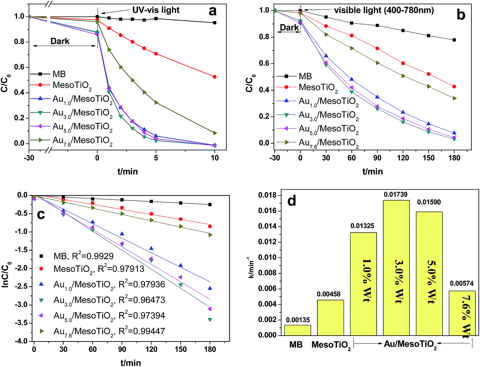 | ||
| Fig. 7 Photodegradation of MB over various samples upon UV-visible light irradiation (a) and visible light irradiation (b). Kinetic linear fitting curves for liquid-phase photocatalytic degradation of MB over different samples under visible light irradiation (c). Value of the rate constant k of the photodegradation of MB over mesoTiO2 and Au/mesoTiO2 composites (d). | ||
The stability of a photocatalyst is very important for practical applications; thus, a durability test was performed to confirm the stability of the Au3.0/mesoTiO2 photocatalyst, which achieved the highest performance. According to Fig. 8a, the MB photodegradation efficiency changed slightly after 5 cycles of the experiment under identical conditions, indicating that the photocatalyst has superior photocatalytic stability. Moreover, the crystallization was well maintained after the recycling test compared to that of Au3.0/mesoTiO2 before the reaction, which is confirmed by the results shown in Fig. 8b. This can be attributed to the synergistic effect of the high intrinsic single-crystal-like nature of the anatase phase, the stability of the gold, and the strong interaction between Au and mesoTiO2.
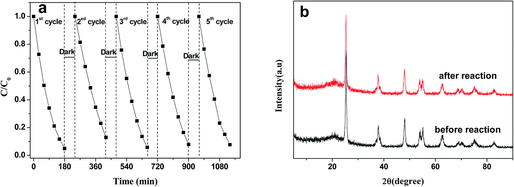 | ||
| Fig. 8 Durability study over Au3.0/mesoTiO2 for MB photodegradation under visible light irradiation (a); XRD patterns of Au3.0/mesoTiO2 before and after the recycling reaction. | ||
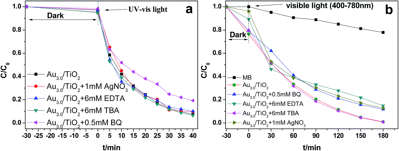
To investigate the main active species during the photodegradation process, additional examination was carried out via dissolving different trapping agents in the reaction solution before light irradiation. Under UV-visible light irradiation, as shown in Fig. 9a, the MB degradation was significantly suppressed when benzoquinone (BQ), a scavenger for ˙O2− radicals, was added to the reaction system.42 However, other radical scavengers presented no influence on photoactivity. This indicated that the ˙O2− radical was the main active species during the photodegradation process. It is interesting to note that, under visible light irradiation, the results were different, as shown in Fig. 9b. When the photo-generated holes and electrons were trapped with EDTA and AgNO3, respectively, the degradation was moderately suppressed. Similarly, when BQ was added to the reaction system, a weaker decrease of the degradation rate was also observed, indicating that ˙O2− radical was not the only active species under these conditions. Regardless of the kind of light excitation, no significant changes occurred in dye degradation when an ˙OH scavenger, TBA, was added to the degradation system.43 Accordingly, a possible reaction process can be proposed as follows. The mechanisms for the photocatalytic activity of Au/mesoTiO2 under UV light excitation and visible light excitation are different. As is demonstrated by XPS, Au and mesoTiO2 form a Schottky junction; the metal Au acts as the anode, and the n-type mesoTiO2 acts as the cathode. Under simultaneous UV and visible light irradiation (Scheme 1, left part), the electrons of TiO2 are rapidly promoted from the valence band (VB) to the conduction band (CB), while the holes remain in the VB (eqn (1)). Electrons can be readily transferred from CB to metallic Au through a Schottky junction (eqn (2)), which extends the lifetime of the electrons. Then the electrons reduce O2 adsorbed on the Au surface to form ˙O2− and further generate ˙HO2 (eqn (3) and (4)). Finally, MB molecules adsorbed on the Au surface are oxidized by ˙O2− and ˙HO2 together. Meanwhile, the holes can initiate the direct oxidation of MB molecules (eqn (5)).
| MesoTiO2 + hν (≥Eg) → mesoTiO2(ecb− + hvb+) | (1) |
| MesoTiO2(ecb−) + Au → mesoTiO2–Au(e−) | (2) |
| MesoTiO2–Au(e−) + O2 → mesoTiO2–Au + ˙O2− | (3) |
| ˙O2− + H2O → ˙HO2 + OH− | (4) |
| h+, ˙O2− or ˙HO2 + MB → degraded product | (5) |
 | ||
| Fig. 9 Reaction process for the photocatalytic degradation of MB over Au3.0/mesoTiO2 catalyst with and without trapping agents. (a) Under UV-visible light irradiation, (b) under visible light irradiation. | ||
 | ||
| Scheme 1 Proposed mechanism for the photocatalytic activity of Au/mesoTiO2 under UV light excitation (left) and upon excitation of the gold surface plasmon band (right). | ||
Under visible light irradiation, mesoTiO2 exhibited low photocatalytic ability due to its slight absorption “tail” (Fig. 5). Once Au NPs are incorporated into mesoTiO2, upon visible light irradiation, as is shown in Scheme 1 (right part), intense SPR-enhanced EM fields and resonant photon scattering are generated on the Au NP surface, significantly increasing the yield of interfacial “hot electrons” with a higher potential energy than the Schottky barrier height at the interface (eqn (6));44 the position of the Fermi level will be shifted closer to the CB of mesoTiO2.45 Subsequently, the “hot electrons” are transferred to the CB of mesoTiO2 (eqn (7)). The Schottky barrier at the interface also helps the transferred “hot” electrons accumulate in the TiO2 CB, preventing them from traveling back to the Au NPs. Since no holes are generated in the valence band (VB) of TiO2, the transferred “hot electrons” in the TiO2 CB should have much longer lifetimes, offering more probability to reduce the O2 adsorbed on the mesoTiO2 surface and the consequent MB degradation.
It is known that the reduction potential of the electron scavenger Ag+ (+0.80 V vs. NHE at pH 7) is much higher than the TiO2 CB minimum (−0.1 V), while lower than that of Au+ (+1.70 V). Thus, Ag+ can easily be reduced by the transferred electrons within the TiO2 CB minimum but cannot be reduced by the electrons on Au. We observed this phenomenon in our experiments; MB degradation was not suppressed by the addition of electron scavengers under UV-vis light irradiation but was suppressed under visible light irradiation. Under visible light irradiation, the h+ remaining on Au greatly facilitates its chelation by EDTA, which is consistent with the experimental phenomenon, shown in Fig. 9b, that MB degradation was obviously suppressed by the addition of EDTA. The photoreaction process is very quick,46 and ˙O2− radicals, e− and h+ are simultaneously responsible for the photodegradation of MB under visible light irradiation. Obviously, when the abovementioned competition occurs, the h+ will mainly take the charge of the oxidation of MB molecules (400 to 780 nm).
| Au + hν (≥Eg) → Au(e− + h+) | (6) |
| Au(e−) + mesoTiO2 → Au–mesoTiO2(ecb−) | (7) |
4. Conclusion
In summary, gold nanoparticles were incorporated into nanoporous anatase TiO2 mesocrystal, denoted as Au/mesoTiO2, to modify the photoresponse properties of TiO2 particles and improve their photocatalytic stability. The exposed active {101} facets, coupled with the loaded Au nanoparticles, dramatically enhanced the visible light photocatalytic performance of the TiO2. SEM and TEM confirmed the structure of the as prepared TiO2 spindle-shaped nanoporous mesocrystals, and the dominant exposed face is the {101} facets; the loaded Au NPs are nearly spherical, with an average size of about 8 nm. XPS results confirmed that the deposited Au NPs were metallic Au(0). UV-vis spectroscopy shows that as the Au content was increased, the plasmon band intensity of Au/mesoTiO2 increased accordingly. BET demonstrates that Au/mesoTiO2 has an ink-bottle structure found in mesoporous materials. The prepared Au/mesoTiO2 catalyst is expected to have potential applications in photocatalytic degradation, photocatalytic water splitting, solar cells, sensors, etc. The findings in our work provide a new way to steadily improve photocatalytic efficiency through the loading of stable noble metals on single-crystal-like mesoTiO2.Acknowledgements
This work was supported by grants from the National Natural Science Foundation of China (No. 21473161 and 21271155), Zhejiang Provincial Top Key Academic Discipline of Chemical Engineering and Technology, Alexander von Humboldt Foundation, and Zhejiang SCI-TECH University for 521 distinguished scholar's scheme.References
- A. Paracchino, V. Laporte, K. Sivula, M. Graetzel and E. Thimsen, Nat. Mater., 2011, 10, 456–461 CrossRef CAS.
- Q. Xiang, J. Yu and M. Jaroniec, J. Am. Chem. Soc., 2012, 134, 6575–6578 CrossRef CAS.
- M. R. Hoffmann, S. T. Martin, W. Y. Choi and D. W. Bahnemann, Chem. Rev., 1995, 95, 69–96 CrossRef CAS.
- H. Xu, S. Ouyang, L. Liu, P. Reunchan, N. Umezawa and J. Ye, J. Mater. Chem. A, 2014, 2, 12642–12661 CAS.
- J. Zhao, L. Zhang, W. Xing and K. Lu, J. Phys. Chem. C, 2015, 119, 7732–7737 CAS.
- N. Feng, Q. Wang, A. Zheng, Z. Zhang, J. Fan, S.-B. Liu, J.-P. Amoureux and F. Deng, J. Am. Chem. Soc., 2013, 135, 1607–1616 CrossRef CAS.
- D. Yang, Y. Sun, Z. Tong, Y. Tian, Y. Li and Z. Jiang, J. Phys. Chem. C, 2015, 119, 5827–5835 CAS.
- M.-Y. Xing, B.-X. Yang, H. Yu, B.-Z. Tian, S. Bagwasi, J.-L. Zhang and X.-Q. Gongs, J. Phys. Chem. Lett., 2013, 4, 3910–3917 CrossRef CAS.
- A. A. Ismail, D. W. Bahnemann, I. Bannat and M. Wark, J. Phys. Chem. C, 2009, 113, 7429–7435 CAS.
- H. Wang, Y. Fu, T. Han, J. Wan and X. Zheng, RSC Adv., 2015, 5, 33570–33578 RSC.
- H. Wang, D. Zhou, Z. Wu, J. Wan, X. Zheng, L. Yu and D. L. Phillips, Mater. Res. Bull., 2014, 57, 311–319 CrossRef CAS.
- H. Wang, D. Zhou, S. Shen, J. Wan, X. Zheng, L. Yu and D. L. Phillips, RSC Adv., 2014, 4, 28978–28986 RSC.
- L. Liu, X. Gu, C. Sun, H. Li, Y. Deng, F. Gao and L. Dong, Nanoscale, 2012, 4, 6351–6359 RSC.
- H. Tada, Q. Jin, H. Nishijima, H. Yamamoto, M. Fujishima, S.-i. Okuoka, T. Hattori, Y. Sumida and H. Kobayashi, Angew. Chem., Int. Ed., 2011, 50, 3501–3505 CrossRef CAS.
- T. Han, D. Zhou, H. Wang and X. Zheng, J. Environ. Chem. Eng., 2015, 3, 2453–2462 CrossRef CAS.
- X. Fu, B. Wang, C. Chen, Z. Ren, C. Fan and Z. Wang, New J. Chem., 2014, 38, 4754–4759 RSC.
- L. Zhou, D. Smyth-Boyle and P. O'Brien, J. Am. Chem. Soc., 2008, 130, 1309–1320 CrossRef CAS.
- Z. Bian, T. Tachikawa and T. Majima, J. Phys. Chem. Lett., 2012, 3, 1422–1427 CrossRef CAS.
- Z. Hong, M. Wei, T. Lan, L. Jiang and G. Cao, Energy Environ. Sci., 2012, 5, 5408–5413 CAS.
- C. Hu, X. Zhang, X. Li, Y. Yan, G. Xi, H. Yang and H. Bai, Chem.–Eur. J., 2014, 20, 13557–13560 CrossRef CAS.
- L. Liu, P. Li, B. Adisak, S. Ouyang, N. Umezawa, J. Ye, R. Kodiyath, T. Tanabe, G. V. Ramesh, S. Ueda and H. Abe, J. Mater. Chem. A, 2014, 2, 9875–9882 CAS.
- L. Liu, S. Ouyang and J. Ye, Angew. Chem., Int. Ed., 2013, 52, 6689–6693 CrossRef CAS.
- P. Christopher, H. Xin, A. Marimuthu and S. Linic, Nat. Mater., 2012, 11, 1044–1050 CAS.
- D. Ding, K. Liu, S. He, C. Gao and Y. Yin, Nano Lett., 2014, 14, 6731–6736 CrossRef CAS PubMed.
- Z. Bian, T. Tachikawa, P. Zhang, M. Fujitsuka and T. Majima, J. Am. Chem. Soc., 2014, 136, 458–465 CrossRef CAS.
- L. Du, A. Furube, K. Yamamoto, K. Hara, R. Katoh and M. Tachiya, J. Phys. Chem. C, 2009, 113, 6454–6462 CAS.
- K. Qian, B. C. Sweeny, A. C. Johnston-Peck, W. Niu, J. O. Graham, J. S. DuChene, J. Qiu, Y.-C. Wang, M. H. Engelhard, D. Su, E. A. Stach and W. D. Wei, J. Am. Chem. Soc., 2014, 136, 9842–9845 CrossRef CAS.
- M. A. Elmoula, E. Panaitescu, M. Phan, D. Yin, C. Richter, L. H. Lewis and L. Menon, J. Mater. Chem., 2009, 19, 4483–4487 RSC.
- R. Zanella, S. Giorgio, C. R. Henry and C. Louis, J. Phys. Chem. B, 2002, 106, 7634–7642 CrossRef CAS.
- Z. Hong, K. Zhou, J. Zhang, Z. Huang and M. Wei, J. Mater. Chem. A, 2015, 3, 17412–17416 CAS.
- J. Ye, W. Liu, J. Cai, S. Chen, X. Zhao, H. Zhou and L. Qi, J. Am. Chem. Soc., 2011, 133, 933–940 CrossRef CAS.
- F. Chen, F. Cao, H. Li and Z. Bian, Langmuir, 2015, 31, 3494–3499 CrossRef CAS.
- Y. Wu, J. Zhang, L. Xiao and F. Chen, Appl. Catal., B, 2009, 88, 525–532 CrossRef CAS.
- J. Li and H. C. Zeng, Chem. Mater., 2006, 18, 4270–4277 CrossRef CAS.
- M. Xing, J. Zhang, F. Chen and B. Tian, Chem. Commun., 2011, 47, 4947–4949 RSC.
- H. Wang, J. L. Faria, S. Dong and Y. Chang, Mater. Sci. Eng., B, 2012, 177, 913–919 CrossRef CAS.
- F. Tian, Y. Zhang, J. Zhang and C. Pan, J. Phys. Chem. C, 2012, 116, 7515–7519 CAS.
- Y. Li, H. Wang, Q. Feng, G. Zhou and Z.-S. Wang, Energy Environ. Sci., 2013, 6, 2156–2165 CAS.
- A. Ayati, A. Ahmadpour, F. F. Bamoharram, B. Tanhaei, M. Manttari and M. Sillanpaa, Chemosphere, 2014, 107, 163–174 CrossRef CAS.
- C. Gomes Silva, R. Juarez, T. Marino, R. Molinari and H. Garcia, J. Am. Chem. Soc., 2011, 133, 595–602 CrossRef CAS.
- K. Takahiro, S.-i. Naya and H. Tada, J. Phys. Chem. C, 2014, 118, 26887–26893 CAS.
- Y. Zhang, N. Zhang, Z.-R. Tang and Y.-J. Xu, Chem. Sci., 2013, 4, 1820–1824 RSC.
- C. Pan and Y. Zhu, Environ. Sci. Technol., 2010, 44, 5570–5574 CrossRef CAS PubMed.
- J. Y. Park, S. M. Kim, H. Lee and B. Naik, Catal. Lett., 2014, 144, 1996–2004 CrossRef CAS.
- S. P. Lim, A. Pandikumar, N. M. Huang and H. N. Lim, RSC Adv., 2015, 5, 44398–44407 RSC.
- K. Ozawa, M. Emori, S. Yamamoto, R. Yukawa, S. Yamamoto, R. Hobara, K. Fujikawa, H. Sakama and I. Matsuda, J. Phys. Chem. Lett., 2014, 5, 1953–1957 CrossRef CAS PubMed.
| This journal is © The Royal Society of Chemistry 2016 |