
 Open Access Article
 This Open Access Article is licensed under a
 Creative Commons Attribution 3.0 Unported Licence
Young's modulus and Poisson's ratio for TiO2-based nanotubes and nanowires: modelling of temperature dependence
Sergey I.
Lukyanov
*,
Andrei V.
Bandura
and
Robert A.
Evarestov
St. Petersburg State University, 7/9 Universitetskaya nab., St. Petersburg, 199034, Russia. E-mail: s.lukyanov@spbu.ru
First published on 29th January 2016
Abstract
In this work molecular mechanics simulations with the help of interatomic potentials were employed to predict the temperature dependence of the Young's modulus and Poisson's ratio of a number of TiO2-based four-facetted nanotubes and nanowires. The temperature dependence of the Young's modulus was obtained through the calculation of the Helmholtz free energy of the system under isothermal thermodynamic conditions. The Helmholtz free energy simulations were performed in the framework of quasi-harmonic approximation as a result of calculations of the potential energy and the harmonic phonon frequencies of the system under consideration. The Helmholtz free energy calculated for the set of fixed values of the nanoobject translational period allows obtaining the minimal Helmholtz free energy at specified temperatures in the range 0–1000 K. The present simulations demonstrate that the Young's modulus for the TiO2-based nanowires decreases with the increase of the nanowire diameters, and approaches the modulus for the rutile bulk crystal from above. Also, the temperature behavior of the Young's modulus, Poisson's ratio and period for the nanotubes and nanowires are considered. This study reveals that the Poisson's ratios of the nanotubes and nanowires depend on the surface atoms chosen to measure the transverse dimensions of the nanostructures.
Introduction
The mechanical properties of TiO2-based nanostructures (nanotubes, NTs, and nanowires, NWs) are important due to their practical applications. In particular, the strengthening of polystyrene films with small amounts of the TiO2-based nanotubes enables the increase of the Young's modulus of the nanohybrid films by 18% and the tensile strength by 30%.1 In medicine, the treatment of the surface of metallic titanium implants with TiO2 nanotubes improves osteointegration of the implant and prevents dislocation and premature loosening. The stability of the implant surface is determined by the elastic modulus of TiO2 nanotubes and nanowires.2–4Titania nanowires have exceptional photocatalytic and photovoltaic activity, and outstanding optical properties.5 The mechanical characteristics of NWs are very important to understand the possibility of developing reliable photovoltaic and photocatalytic cells, and optical and electrical devices based on titania nanowires.6
Experimental measurements of the elastic properties of the nanostructures based on ZnO, TiO2 and other inorganic compounds give strongly different results.6–11 Additional information on the behavior of TiO2 nanostructures under mechanical loads at different temperatures can be obtained by theoretical modelling of the temperature dependence of the Young's modulus.
A number of computer-aided studies has been performed to investigate the temperature dependence of the mechanical properties of the single-walled, double-walled carbon nanotubes12–17 and carbon-based nanomaterials such as the fullerene and nanotube derivatives.18 The main approaches used in these works are the classical molecular dynamics with empirical potentials and semiempirical tight binding molecular dynamics.12,13,17 The temperature dependence of the Young's modulus, Y, for the nanotubes has been simulated using the determination of strain for a fixed stress16,17 and the determination of stress for a fixed strain techniques.17–19 Also, the temperature dependence of the stiffness of single-walled carbon nanotubes has been estimated by the molecular dynamics simulations of the intrinsic thermal vibrations of a single-walled carbon nanotube modelled as a clamped cantilever.12 The Young's modulus values were calculated from the equation relating the modulus and standard deviation of the vibrational amplitude of the tube's free tip displacement.
The results of Dereli and Süngü17 indicate that the Young's modulus of (10, 10) nanotube decreases in the interval 0 K < T < 1000 K but increases at temperature higher than 1000 K. The (10, 10) nanotube also has been studied by Zhang and Shen.13 The authors of mentioned papers employed different values of the nanotube's wall thickness δ. For comparing the results one can use an area-based Young's modulus YS = Yδ.20 Our comparison of these studies' results reveals that the YS values may differ by as much as 2.8 times.
Jin-Yuan Hsieh et al.12 investigated the carbon zig-zag nanotubes (n, 0) with n = 7, 9, 12 and higher and a (5, 5) armchair nanotube. As follows from Fig. 3 of this paper,12 the Young's modulus of almost all considered nanotubes are invariable or demonstrate small growth in temperature interval from 100 K to 1000 K.
In the work of H. Jiang et al.21 a finite-temperature constitutive model not involving molecular dynamics simulation was established. The model using harmonic vibrational frequency and quasi-harmonic approximation22 allows one to simulate the Helmholtz free energy and to compute the temperature dependence of the mechanical properties for the nanosystem. This model has been applied to the investigation of the Young's modulus and Poisson ratio of graphene.
In recent years the investigations of the mechanical properties of the inorganic nanotubes23–27 and nanowires11,28–32 have been carried out. However, to the best of our knowledge, the only study on the temperature dependence of the mechanical properties of the inorganic nanoobjects is published in our recent article.33
Our previous paper33 presents the results of the study of the Young's modulus temperature dependence of the TiO2-based cylindrical single-walled nanotubes with zig-zag and armchair chiralities and nanotubes with consolidated single wall (CSW NT). The latter are obtained from the cylindrical coaxial double-walled NTs by merging the single-walled constituents. The cylindrical single-walled constituents of the NTs were rolled up from the (111) 3-plane slab cut from a fluorite phase TiO2 crystal, space group Fm![[3 with combining macron]](https://www.rsc.org/images/entities/char_0033_0304.gif) m.
m.
The used33 quasi-harmonic approximation and Helmholtz free energy simulation based on harmonic vibrational frequency is more simple method than the molecular dynamics modelling and it can produce the consistent results.
The present paper has five parts. In the section “Method” the theoretical background of the elastic moduli calculations and relevant formulae are described. The section “Nanostructure models and computational details” presents the nanoobject models used and describes the applied atom–atom force field and specific characteristics of the computational procedure. The analysis of the obtained data and the discussion of the results are arranged in the section “Results and discussion”. The summary of the present study conclusions is given in the last section “Conclusions”.
Method
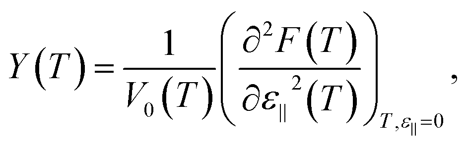
One of the main mechanical characteristics of a nanotube is the Young's modulus: | (1) |
| ε∥ = (L − L0)/L0 | (2) |
 | (3) |
Combining eqn (1) and (2) one can get
 | (4a) |
 | (4b) |
To obtain the Young's modulus from the results of computer simulation the change in the total internal energy of the nanosystem during an isothermal process is frequently applied as follows.25,27
 | (4c) |
However the more correct way to compute the Young's modulus Y(T) considering an isothermal process is to use the eqn (4b).
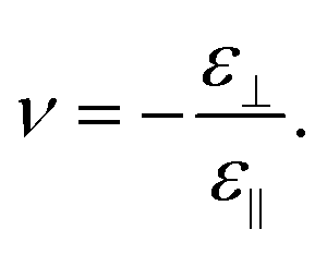
The second quantity describing the mechanical properties of the nanostructures is the Poisson's ratio:
 | (5) |
The transverse strain ε⊥ appears as a respond to exerting the longitudinal stress or uniaxial pressure σ on the nanostructure. The strain ε⊥ is defined as follows:
| ε⊥ = (D − D0)/D0, | (6) |
 | (7) |
The Young's modulus and the Poisson's ratio are independent elastic properties.35
The molecular mechanics (MM) modelling of the structural and mechanical properties of the nanosystems has been carried out by us with the help of GULP program package.36 Using an empirical force field the potential energy and the phonon harmonic frequencies of the considered nanotubes and nanowires were calculated. The calculated in harmonic approximation vibrational frequencies of the considered nanotubes or nanowires have been computed to obtain the temperature-dependent Helmholtz free energy. The temperature-dependent Helmholtz free energy is the sum of zero point vibrational energy E0 and the contribution of the temperature-dependent free harmonic phonon energy F(T). The zero point energy and the Helmholtz free energy are given by the well-known equation:
 | (8a) |
 | (8b) |
The optimization of the atomic structure of the nanowire or nanotube is the first step of the elastic moduli simulation using quasi-harmonic approximation.22 Thus, the period of the optimized structure L* corresponds to the minimal potential energy of the system: the term U in eqn (8). To obtain the dependence of the energy and transverse strain ε⊥ on the axial strain ε∥ seven contracted and nine elongated samples have been considered: Li = L*(1 + iΔε∥); i = −7, …, 0, 1, …, 9. The strain step Δε∥ = 0.003 was taken the same as in molecular dynamics simulations of the Young's modulus for the carbon nanotubes.19
For each sample the period Li was fixed and potential energy minimization procedure executed to get the optimized atomic structure in local minimum of the potential energy U(ε*∥,i). The Helmholtz free energy was calculated according to eqn (8a) for every optimized structure of the initial, contracted and elongated samples. The calculations were done at temperatures Tj in the temperature interval from 0 K to 200 K with the step ΔT = 25 K and in the interval from 200 K to 1000 K with the step ΔT = 50 K. A number of data sets F(ε*∥,i, Tj) with ε*∥,i = (Li − L*)/L* and Tj from the abovementioned temperature interval have been obtained. A five-degree polynomial was fitted to every Helmholtz free energy data set F(ε*∥,i, Tj) at fixed temperature Tj. These polynomials allow one to calculate the second derivative of F(ε*∥, Tj) in respect to tensile uniaxial strain ε*∥.
The minimum of U(ε*∥) is located at ε*∥ = 0 and independent of T, whereas a position of the F(ε*∥, Tj) minimum does not coincide with that of U(ε*∥) and changes with T increase. As discussed above, the Young's modulus can be obtained using eqn (4b), where the Helmholtz energy is a function of strain ε0,T∥ = (L − L0,T)/L0,T and L0,T is the period of the unstrained nanostructure with a the minimal Helmholtz free energy at temperature T. The relationship between the periods L* and L0,T can easily be obtained: L0,T = L*(ε0,T∥ + 1). The relation between the second derivatives of F in respect to ε*∥ and in respect to ε0,T∥ is as follows:
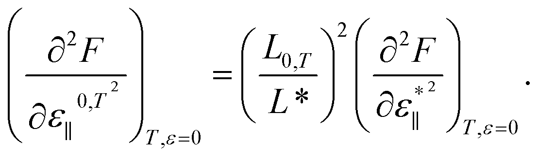 | (9) |
The usage of the unit cell parameters corresponding to the Helmholtz free energy minimum at fixed temperature determines the quasi-harmonic approximation. To find Helmholtz free energy minimum the vibrational frequencies are calculated for the certain range of the unit cell parameters. At the same time, the vibrational frequencies is obtained assuming that the atomic vibrations are harmonic.
Also, for each sample the transverse size of the sample Di and, consequently, the data set Di(Li) was obtained. A quadratic polynomial was fitted to the Di(Li) data set, that allows one to calculate the transverse size D0,T and the derivative (∂D/∂L)L0,T corresponding to L0,T. The Poisson's ratio at temperature T was calculated according to the equation
 | (10) |
Nanostructure models and computational details
As it was shown in our earlier study37 the double- and triple-walled cylindrical coaxial TiO2-based NTs merge producing NTs with consolidated single wall. Depending on the NTs chirality and an interwall distance, the resulting consolidated single wall consists of planar and/or curved sections of the slab together with some elements of the rutile structure as in Fig. 1a. However it appears that modelling of the NTs elongation and compression allows us to perform a more detailed study of the NT potential energy surface and, in some cases, to find an optimized structure with lower potential energy. In that way in our present work a more stable optimized structure of the (8, 8)@(12, 12)@(16, 16) CSW NT with 72 TiO2 formula units (FU) per NT unit cell (UC) was obtained, see Fig. 1b. One can see from Fig. 1b that this more stable structure is very close to the one of the rutile-based four-facetted nanotubes (FNT) shown in Fig. 2a and contains 72 FU per UC. In one's turn this four facetted nanotube is obtained through cutting a smallest (9 TiO2 FU per UC) four-facetted Ti atom centered nanowire from a largest (81 FU per UC) four-facetted nanowire (FNW), see Fig. 3a and 2b, respectively. Both nanowires under consideration, largest and smallest ones, are cut from rutile titania bulk along the [001] direction passing through Ti atoms.5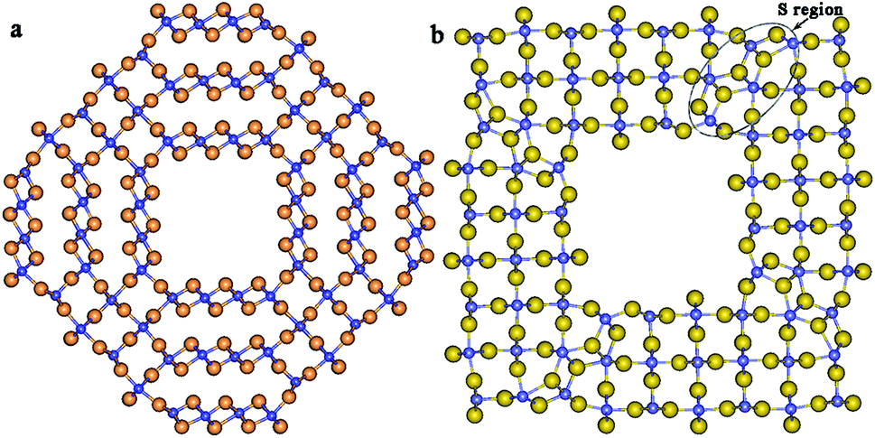 | ||
| Fig. 1 Cross-section images of the (8, 8)@(12, 12)@(16, 16) CSW NT with 72 FU per UC: (a) an intermediate structure; (b) the distorted FNT structure with minimum potential energy. Larger light spheres are oxygen ions, smaller dark spheres are titanium ions. | ||
 | ||
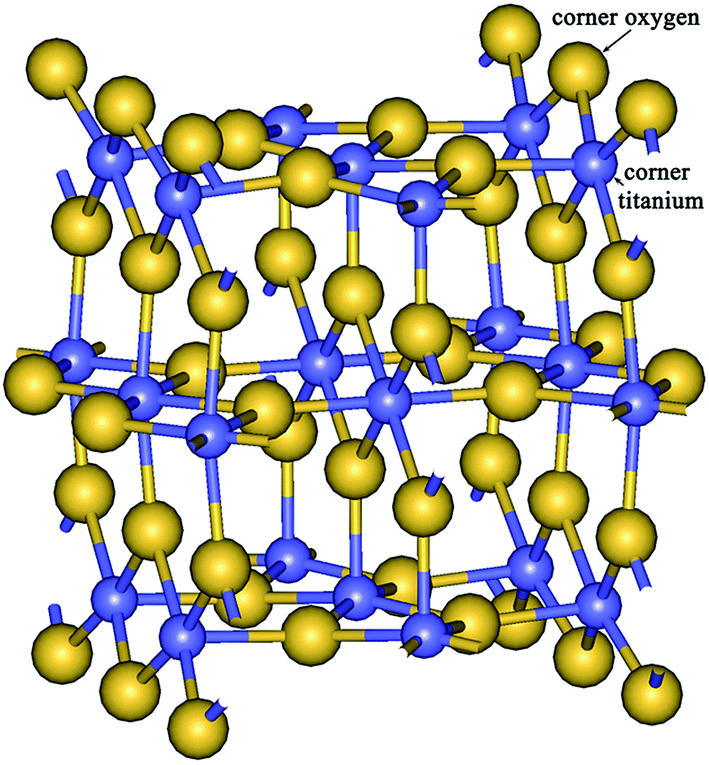
| Fig. 2 Cross-sectional images of the nanostructures of rutile morphology: (a) FNT with 72 formula units per UC and (b) largest FNW with 81 formula units per UC. O1, O2, O3 are corner oxygen atoms; O4, O5, O6 and O7 are edge oxygen atoms. | ||
 | ||
| Fig. 3 Cross-sectional images of the nanowires of rutile morphology: (a) Ti atom-centered smallest; (b) hollow site-centered small; (c) Ti atom-centered middle and (d) hollow site-centered large with 9, 16, 25 and 64 formula units per UC, respectively. The distances d1, d2, d3, d4 between edge oxygen atoms and diameters DOO and DTiTi are shown in (b) and (c) by twice-terminated arrows. O1, O2, O3, O4, O7, O8, O9, O10 are edge oxygen atoms; O5 and O6 are corner oxygen atoms. | ||
The largest part of the wall of CSW NT consists of the rutile-like elements. The small number of the fluorite-like elements (see region S in Fig. 1b) is included in the nanotube's wall and distorts the structure which is basically similar to the structure of the four-facetted NT, Fig. 2a. In that way the (8, 8)@(12, 12)@(16, 16) CSW NT can be defined as a distorted four-facetted NT. The morphology38 and electronic properties39 of anatase-based facetted NTs and rutile-based facetted NWs have been considered. The structural and electronics properties of [001]-oriented Ti atom-centered and hollow site-centered NWs have been investigated by large-scale ab initio Density Functional Theory (DFT) and hybrid DFT–Hartree Fock (DFT–HF) calculations.40
In that way, the subject of the present study is the calculation of the elastic properties temperature dependence of the seven objects: two nanotubes (distorted four-facetted NT with 72 formula units per UC (Fig. 1b), four-facetted NT with 72 FU per UC (Fig. 2b)), and five nanowires (four-facetted [001]-oriented Ti atom-centered NWs with 81, 9, 25 (middle FNW) FU per UC, Fig. 2b, 3a and b, and hollow site-centered NWs with 16 (small FNW), 64 (large FNW) FU per UC (Fig. 3c and d).
A lot of atom–atom interaction potentials have been developed for simulating a variety of structures and diverse properties of the different polymorphs of TiO2. These force fields were employed in the Monte Carlo,41 molecular mechanics and molecular dynamics studies42–49 of the crystals. We have tested the ability of these different force fields to reproduce the values of the structural and mechanical parameters and phonon frequencies of four known phases of TiO2 crystals: rutile, anatase, brookite, and columbite. In addition, we tested the ability of the force fields to reproduce the structure and phonon frequencies of the (111) 3-plane slab of a fluorite-like TiO2 crystal and two cylindrical nanotubes (6, 6) and (12, 12) rolled up from such a slab. As far as we know, there are no the experimental data on the properties of the mentioned fluorite layer and two nanotubes. Therefore values of the structural parameters and phonon frequencies of the slab and nanotubes were obtained from our DFT calculations. The practice of employing the results of quantum chemical studies for parameterization of the force fields is widely used.48,50,51
Our comparison of DFT and force field calculations results shows that the lattice parameters and mechanical properties of the four mentioned polymorphs of TiO2 are reproduced well by the force field of Kim et al.46 and, slightly worse, by the one of Matsui and Akaogi (M&A).45 However, the phonon frequencies of these TiO2 phases and nanotubes are reproduced more accurately by means of the M&A interaction potential. Thus, the force field used in the present work is a set of atom–atom interaction potentials developed by Matsui and Akaogi45 with the use of the molecular dynamics modelling.
Table 1 demonstrates the ability of the M&A force field to reproduce the lattice constants of rutile crystal. The optimization of atomic structure has been done through the minimization of potential energy of the system in the MM calculations with the GULP package.36 The DFT calculation results are taken from Evarestov and Zhukovskii.40 The structure optimization is implemented as the potential energy minimization with the help of the conjugate gradient algorithm. As one can see, the discrepancy between DFT PBE results and experimental data is 1% and the corresponding discrepancy for the MM simulations with M&A force field is 2%.
The value of the nanostructure's volume per unit cell is the key parameter for the Young's modulus determination, see eqn (4a) and (4b). The volume of an unstrained facetted nanowire at a temperature T can be calculated as a product of the period of unit cell, L0,T, and the area of the cross-section of NW (Fig. 2b and 3), S. The nanowire period is well defined quantity. However, the NW cross-section area cannot be defined unambiguously. The area of the largest FNW cross-section should be a product of the length of NW cross-section (110) facet side and the length of NW cross-section (1![[1 with combining macron]](https://www.rsc.org/images/entities/char_0031_0304.gif) 0) facet side. The length of NW cross-section (110) facet side can be estimated as the distance between nuclei of the two corner oxygen atoms O1 and O2, dOO = 27.52 Å (Fig. 2b). In one's turn the length of the NW cross-section (10) facet side is a distance between two corner oxygen atoms O2 and O3, dOO = 25.93 Å. On the other hand, the same quantities can also be estimated as the distances between O4–O5 atoms and O6–O7 ones which are 27.89 Å and 27.88 Å, respectively, Fig. 2b. To take into account the size of the oxygen atoms one should also add the quite ambiguous value of the oxygen atom diameter to the obtained values that introduces an extra uncertainty to the cross-section area.
0) facet side. The length of NW cross-section (110) facet side can be estimated as the distance between nuclei of the two corner oxygen atoms O1 and O2, dOO = 27.52 Å (Fig. 2b). In one's turn the length of the NW cross-section (10) facet side is a distance between two corner oxygen atoms O2 and O3, dOO = 25.93 Å. On the other hand, the same quantities can also be estimated as the distances between O4–O5 atoms and O6–O7 ones which are 27.89 Å and 27.88 Å, respectively, Fig. 2b. To take into account the size of the oxygen atoms one should also add the quite ambiguous value of the oxygen atom diameter to the obtained values that introduces an extra uncertainty to the cross-section area.
The calculation of volume of other FNWs is else less unequivocal process. The irregularities of the facets surface have noticeable contribution to the nanowire structure. Moreover, the significantly smaller distances between the corner oxygen atoms (for example, in the smallest FNW, Fig. 3a) become comparable with the ambiguous atomic diameter.
In the present study we applied the method of nanostructure volume calculation analogous to the one employed in the previous research.33 At first, the calculation of molar volume VM of the unstrained largest FNW at T = 0 K was performed using the geometrical parameters of the nanowire and the effective anion radius. As in previous study,33 the effective radius of the three-coordinated oxygen anion R = 1.36 Å (ref. 53) was chosen for estimating the size of oxygen atom in the nanostructure. The area of the nanowire's cross-section was calculated as a product of (dO1O2 + 2R Å) into (dO2O3 + 2R Å). Finally, the molar volume was estimated as a product of the cross-section area and the period of largest FNW L0,T=0 divided by the number of TiO2 formula units per unit cell. The obtained value of VM is 32.33 Å3. To describe the temperature dependence of the molar volume, the experimentally observed data on the change of the rutile crystal lattice constants with temperature in the interval 15–1280 K were employed.54–59 A three-degree polynomial was fitted to the 19 points data set as follows:
| VM(T) = aT3 + bT2 + cT + d, | (11) |
| V(T) = NFU(aT3 + bT2 + cT + VM(0)), | (12) |
The cylindrical carbon nanotubes have a monoatomic wall and in the case of the Poisson's ratio calculation the only choice of the size D in eqn (5) and (6) is the diameter of the nanotube. The facetted nanotubes and nanowires have several structural parameters to be selected as the size D, Fig. 1–3.
The aside facets (110) and (10) of the hollow site-centered NWs have similar structures, see Fig. 3b and d. To measure a distortion perpendicular to the mechanical load along the NW axis one can choose a distance between two edge oxygen atoms: the distance between O1 and O2, d1, the distance between O3 and O4, d2, or diagonal (diameter) DOO, see Fig. 3b. The aside facets (110) and (10) of the Ti atom-centered NWs have different structures, see Fig. 2b, 3a and c. Because of this the distance between O7 and O8, d3, and the distance between O9 and O10, d4 (see Fig. 3c), are different and apparently have different changes under uniaxial stress. The diameter or diagonal DOO may be an integrated parameter relating both facets.
The oxygen atoms of bulk crystal are three coordinated and titanium atoms are six coordinated. The surface corner (bridging) oxygen atoms of NWs are two coordinated while the titanium atoms are five coordinated (Fig. 4). It is known60–62 that the displacements upon the relaxation of the bridging oxygen and surface titanium atoms can differ by as much as 2 times according to the experimental data60 and else more according to the results of ab initio calculations.61,62 The similar effect is found here for the displacements of atoms in the ridges of the NW. Consequently, the change of the DOO due to uniaxial stress has a significant contribution of the surface oxygen atom shift besides of the total uniform transverse dilation or compression. To consider the influence of the different surface atoms on the Poisson's ratio we used two diagonals, DOO or DTiTi (see Fig. 3b and c), as the size D in eqn (6), (7) and (10) for the computation of Poisson's ratio (νOO or νTiTi, respectively).
 | ||
| Fig. 4 The image of two cells of the smallest nanowire. The two-coordinated surface corner oxygen atom and five-coordinated surface corner titanium atom are marked. | ||
Table 2 demonstrates the values of the distance between corner titanium atoms and between corner oxygen atoms or diagonal or diameter of the FNWs and FNTs under study (see Fig. 2 and 3). As a whole, it follows from Table 2 that the differences between the results of the present simulations and data of DFT large scale study don't exceed 2–3%.
| Nanowire or nanotube size (number of TiO2 formula units per UC) | Present MM simulations | DFT40 | |||||
|---|---|---|---|---|---|---|---|
| NW or NT period, L0,0, Å | Corner Ti–Ti distance DTiTi, Å | Corner O–O distance DOO, Å | NW period, L*, Å | Corner O–O distance DOO, Å | |||
| PBE | PBE0 | PBE | PBE0 | ||||
| 81 (largest) | 3.012 | 35.87 | 37.81 | 2.96 | 2.95 | 39.27 | 38.71 |
| 64 (large) | 3.012 | 31.39 | 33.33 | 2.96 | 2.95 | 34.57 | 34.14 |
| 25 (middle) | 3.011 | 17.96 | 19.97 | 2.94 | 2.93 | 20.71 | 20.48 |
| 16 (small) | 3.010 | 13.50 | 15.43 | 2.94 | 2.92 | 16.09 | 15.89 |
| 9 (smallest) | 3.006 | 9.03 | 10.97 | 2.91 | 2.88 | 11.49 | 11.27 |
| 72 (intact) | 3.013 | 34.89 | 36.59 | — | — | — | — |
| 72 (distorted) | 3.061 | 35.84 | 37.77 | — | — | — | — |
Results and discussion
The results of our molecular-mechanics simulations demonstrate that CSW NT i.e. distorted four-facetted NT has a lower Young's modulus values than that for the four-facetted NT. Simultaneously the temperature dependence of the Young's modulus for the distorted four-facetted NT displays the more intensive decrease of the stiffness with the temperature increase, see Fig. 5. These relations between the elastic characteristics of the two FNTs can easily be attributed to the disturbances which are brought in the structure of the distorted FNT by the fluorite-like elements, Fig. 1b, region S. The presence of the fluorite-like elements in rutile structure provides higher coordination numbers for some titanium and oxygen atoms. Also, Fig. 6 indicates that the period of the distorted FNT is notably greater than the period of the intact (with regular rutile structure) FNT. This observation, probably, reveals one of the possible stages of the Young's modulus diminishing mechanism: the nanotube with mixed structure has additional number of degrees of freedom to relax under external loading and, consequently, to diminish stiffness. | ||
| Fig. 5 Temperature dependence of the Young's modulus for the CSW NT, four-facetted NTs and NWs. | ||
 | ||
| Fig. 6 Temperature dependence of the period of the four-facetted NTs and NWs. | ||
The nanotube pore of the intact facetted nanotube (Fig. 2a) can also be treated as a sort of the FNW structure defect which should reduce the stiffness of the FNT relative to the FNW. As it was aforementioned, the FNT was obtained from largest FNW by cutting a pore. Nevertheless, the Young's modulus for the four-facetted NT with 72 formula units per UC exceeds the Young's modulus not only for the largest four-facetted NW (81 FU), but also for large NW (64 FU) and is more close to the modulus of the middle FNW with 25 formula units per UC, Fig. 5. Also, as it follows from Fig. 6, in contrast to the previous case of the relations between two nanotubes, the FNT with greater stiffness has a longer unit cell than the largest FNW (81 FU per UC) and large FNW (64 FU per UC). The temperature dependence of the Young's modulus for the FNT is almost the same as one for the large FNW, see Fig. 5 and Table 3. At the same time, the Young's modulus temperature dependence of the distorted FNT is the strongest one from all nanostructures under consideration.
| Distorted FNT | FNT | FNW | |||||
|---|---|---|---|---|---|---|---|
| Nanowire or nanotube size (number of TiO2 formula units per UC) | 72 | 72 | 81 | 64 | 25 | 16 | 9 |
| Δ, %, Y(T) | 13.9 | 11.2 | 10.9 | 11.0 | 11.8 | 12.6 | 13.4 |
| Δ, %, L0,T | 0.9 | 0.8 | 0.8 | 0.8 | 0.7 | 0.7 | 0.6 |
The Young's modulus for the FNWs increases with the decrease of FNW's size. The smaller are the nanowire diameters the greater is the rate of modulus value growth. The difference between the Young's modulus values of nanowires with 81 (Y(0) = 368 GPa) and 64 (Y(0) = 371 GPa) FU per UC is small – 1%. The difference is 6% for the small (16 FU) (Y(0) = 404 GPa) and smallest (9 FU) (Y(0) = 429 GPa) facetted nanowires. In other words, one needs to heat FNW (64 FU) up to ≈200 K to level the stiffness of this nanowire and the stiffness of the FNW (61 FU) at 0 K. However, in the case of middle FNW the temperature at ≈600 K is necessary.
The MM simulation with the help of M&A force field gives Y(0) = 366 GPa in the direction [001] and 154 GPa in the direction [100] for the rutile bulk crystal. The corresponding experimental values of the Young's modulus are 386 and 148 GPa.63 The differences are −5% and +4% for the Y in the [001] and [100] directions, respectively, which can be treated as the success of M&A parametrization. According to MM simulation result, the minimal Young's modulus value of all [001]-oriented nanowires is Y(0) = 368 GPa for the largest FNW which is only slightly greater than the corresponding Y for the rutile bulk crystal. Thus, the Young's modulus for the FNWs approaches to the Y for the rutile bulk crystal from above with the increase of nanowire size. At the same time, as it was shown in our study,33 the Young's modulus values of the cylindrical nanotubes with the armchair chirality grow with the nanotube's diameter and approach to the crystal value from below.
The Young's moduli for the nanotubes and nanowires decrease with the temperature increase. The temperature dependence of the Young's modulus for the nanowires becomes more steeply with the decrease of nanowire size, Fig. 5 and Table 3. All Y versus T curves have a characteristic shape and can be split into two parts. In the temperature interval from 0 to ≈100 K, the Young's modulus decreases rather slowly. The rise of temperature above 150–200 K results in a sensitive increase in the slope of Y versus T.
As in the case of the cylindrical single-walled nanotubes,33 the behavior of Young's modulus for the FNWs with temperature correlates with the behavior of the period of the nanowires. However, the length of unit cell of the nanowires increases with heating. Nevertheless, the L0,Tversus T curves can also be split into two parts. In the temperature range 0 ≤ T ≤ 150 K the unit cell length is almost constant, Fig. 6. The periods of all the FNWs and FNTs increase as temperature grows in the second range from ≈150 to 1000 K.
On the whole, the periods of the FNWs decrease with the size decrease, see Fig. 6. However the values of period of the largest FNW (81 formula) and FNW with 64 formula units per UC are close and the corresponding L0,Tversus T curves merge in Fig. 6.
The average increase of the period for FNTs and large-size FNWs with temperature is about 0.8%, Table 3. The temperature dependence of the FNWs' periods diminishes with the nanowire size decrease. These computational data are close to the experimental values of the rutile lattice vectors temperature dependence. The lattice constant a of the rutile crystal increases by as much as 0.7% and the lattice constant c increases by as much as 1.1% with temperature increase from 0 to 1000 K.48
The values of the Poisson's ratio for FNTs and FNWs, νTiTi and νOO, calculated using Ti–Ti and O–O diagonals are listed in Table 4. Firstly, from these data one can see that νOO values are greater than νTiTi values. Secondly, the Poisson's ratio νOO is growing with the decrease of the FNW size from largest to smallest. On the contrary, the Poisson's ratio νTiTi demonstrates reverse dependence on NW size. According to νTiTi the compressibility of the FNT is equal to this parameter of the largest FNW (81 FU), but νOO for the FNT is a little lower than this modulus for the largest FNW. Poisson's ratios νTiTi and νOO have a maximal values for the distorted FNT among the considered nanostructures.
| Distorted FNT | FNT | FNW | |||||
|---|---|---|---|---|---|---|---|
| Nanowire or nanotube size (number of TiO2 formula units per UC) | 72 | 72 | 81 | 64 | 25 | 16 | 9 |
| ν OO | 0.427 | 0.282 | 0.285 | 0.289 | 0.302 | 0.325 | 0.345 |
| ν TiTi | 0.351 | 0.244 | 0.243 | 0.240 | 0.224 | 0.214 | 0.200 |
Both Poisson's ratios decrease in the temperature range 0 to 1000 K for all investigated FNWs and FNT. The decrease is around 1% for the νOO and a little more for the νTiTi – around 1.5%. At the same time, the νOO and νTiTi for the distorted FNT demonstrate the 1.2% growth as the temperature increases from 0 to 1000 K. Interestingly, the temperature behavior of the distorted FNT Poisson's ratios is similar to the one of the bulk crystalline materials and glasses. The ν of these structures is known to generally increase with temperature.35
Conclusions
The Young's modulus for the [001]-oriented rutile-based four-facetted nanowires decreases with the increase of the nanowire size and approaches to the Young's modulus for the rutile bulk crystal from above. The Young's modulus for the four-facetted nanotube with 72 formula units per UC obtained from the nanowire with 81 formula units per UC by cutting the rod-like pore, is larger than the modulus for parent nanowire. The Young's modulus for the distorted FNT is less than the modulus for the intact FNT.The Young's modulus for the FNTs and FNWs decreases with temperature growth. The temperature diminution of the Young's modulus achieves 11–14% and the most significant drop is for the distorted FNT and smallest FNW.
The period of the rutile-based FNWs decreases with the nanowire size decrease. The periods of the similar FNTs are greater than the ones of FNWs and the period of the distorted FNT is significantly longer than others.
The periods of the FNWs and FNTs increase with heating. This increase achieves 0.8% in temperature range 0–1000 K and is in good agreement with the experimental values 0.7–1.1%.
The results of our study indicates that the Poisson's ratio of the TiO2-based FNTs and FNWs depends on the surface atoms chosen to measure the transverse dimensions of NTs and NWs in the plane normal to the tensile stress axis. This is due to the different degree of relaxation under tensile stress of the chosen surface atoms. In addition, the values of the surface atoms displacements determine the trend of the Poisson's ratio change with the FNW size increase, namely, it may grow or diminish. Apparently, the mentioned effects decrease with the increase of NW size.
The temperature dependence of the νOO and νTiTi for the TiO2-based FNTs and FNWs is weak. Using the quasi harmonic approximation, the Poisson's ratios for all investigated FNWs and intact FNT tends to decrease by as much as 1–1.5% with temperature growth from 0 to 1000 K. By contrast, the Poisson's ratios for the distorted FNT increases in the same temperature range.
Acknowledgements
The authors wish to acknowledge the financial support by the Russian Foundation for Basic Research (grant no. 14-03-00107-a) and the assistance of St. Petersburg State University Computer Center in high-performance calculations.Notes and references
- S. Kaur, M. Gallei and E. Ionescu, Adv. Polym. Sci., 2015, 267, 143–186 CrossRef CAS.
- A. W. Tan, B. Pingguan-Murphy, R. Ahmad and S. A. Akbar, Ceram. Int., 2012, 38, 4421–4435 CrossRef CAS.
- L. S. Santos, N. T. C. Oliveira, C. M. Lepienski, C. E. B. Marino and N. K. Kuromoto, Rev. Mater., 2014, 19, 33–39 Search PubMed.
- A. W. Miles and S. Gheduzzi, Surgery, 2012, 30, 86–91 Search PubMed.
- R. A. Evarestov, D. B. Migas and Y. F. Zhukovskii, J. Phys. Chem. C, 2012, 116, 13395–13402 CAS.
- Z. Ye, H. Zhu, Y. Zheng, W. Dong and B. Chen, Mater. Sci. Eng., A, 2015, 641, 281–289 CrossRef CAS.
- Q. Qin, F. Xu, Y. Cao, P. I. Ro and Y. Zhu, Small, 2012, 8, 2571–2576 CrossRef CAS PubMed.
- D. Jiang, C. Tian, Q. Liu, M. Zhao, J. Qina, J. Hou, S. Gao, Q. Liang and J. Zhao, Mater. Sci. Eng., A, 2014, 610, 1–4 CrossRef CAS.
- S. S. Amin, S.-you Li, X. Wu, W. Ding and T. T. Xu, Nanoscale Res. Lett., 2010, 5, 338–343 CrossRef CAS PubMed.
- L. Borgese, M. Gelfi, E. Bontempi, P. Goudeau, G. Geandier, D. Thiaudière and L. E. Depero, Surf. Coat. Technol., 2012, 206, 2459–2463 CrossRef CAS.
- C. Q. Chen, Y. Shi, Y. S. Zhang, J. Zhu and Y. J. Yan, Phys. Rev. Lett., 2006, 96, 075505 CrossRef CAS PubMed.
- J.-Y. Hsieh, J.-M. Lu, M.-Y. Huang and C.-C. Hwang, Nanotechnology, 2006, 17, 3920–3924 CrossRef CAS.
- C.-L. Zhang and H.-S. Shen, Appl. Phys. Lett., 2006, 89, 081904 CrossRef.
- C.-L. Zhang and H.-S. Shen, J. Phys. D: Appl. Phys., 2008, 41, 055404 CrossRef.
- F. Scarpa, L. Boldrin, H. X. Peng, C. D. L. Remillat and S. Adhikari, Appl. Phys. Lett., 2010, 97, 151903 CrossRef.
- N. R. Raravikar, P. Keblinski, A. M. Rao, M. S. Dresselhaus, L. S. Schadler and P. M. Ajayan, Phys. Rev. B: Condens. Matter Mater. Phys., 2002, 66, 235424 CrossRef.
- G. Dereli and B. Süngü, Phys. Rev. B: Condens. Matter Mater. Phys., 2007, 75, 184104 CrossRef.
- J. Y. Wu, J. Y. He and Z. L. Zhang, Comput. Mater. Sci., 2013, 80, 15–26 CrossRef CAS.
- P. M. Agrawal, B. S. Sudalayandi, L. M. Raff and R. Komanduri, Comput. Mater. Sci., 2006, 38, 271–281 CrossRef CAS.
- E. Hernandez, C. Goze, P. Bernier and A. Rubio, Phys. Rev. Lett., 1998, 80, 4502–4505 CrossRef CAS.
- H. Jiang, Y. Huang and K. C. Hwang, J. Eng. Mater. Technol., 2005, 127, 408–416 CrossRef CAS.
- R. P. Stoffel, C. Wessel, M.-W. Lumey and R. Dronskowski, Angew. Chem., Int. Ed. Engl., 2010, 49, 5242–5266 CrossRef CAS PubMed.
- I. Kaplan-Ashiri, S. R. Cohen, K. Gartsman, R. Rosentsveig, G. Seifert and R. Tenne, J. Mater. Res., 2004, 19, 454–459 CrossRef CAS.
- I. Kaplan-Ashiri, S. R. Cohen, K. Gartsman, V. Ivanovskaya, T. Heine, G. Seifert, I. Wiesel, H. D. Wagner and R. Tenne, Proc. Natl. Acad. Sci. U. S. A., 2006, 103, 523–528 CrossRef CAS PubMed.
- M. Griebel, J. Hamaekers and F. Heber, Comput. Mater. Sci., 2009, 45, 1097–1103 CrossRef CAS.
- T. Lorenz, D. Teich, J.-O. Joswig and G. Seifert, J. Phys. Chem. C, 2012, 116, 11714–11721 CAS.
- E. W. Bucholz and S. B. Sinnott, J. Appl. Phys., 2012, 112, 123510 CrossRef.
- L. Dai, C. H. Sow, C. T. Lim, W. C. D. Cheong and V. B. C. Tan, Nano Lett., 2009, 9, 576–582 CrossRef CAS PubMed.
- G. Wang and X. Li, J. Appl. Phys., 2008, 104, 113517 CrossRef.
- Y.-B. Wang, L.-F. Wang, H. J. Joyce, Q. Gao, X.-Z. Liao, Y.-W. Mai, H. H. Tan, J. Zou, S. P. Ringer, H.-J. Gao and C. Jagadish, Adv. Mater., 2011, 23, 1356–1360 CrossRef CAS PubMed.
- L. Dai, C. H. Sow, C. T. Lim and V. B. C. Tan, in Nanowires - Fundamental Research, ed. A. Hashim, InTech, University Campus STeP Ri, Slavka Krautzeka 83/A 51000 Rijeka, Croatia, 2011, vol. 9, pp. 183–202 Search PubMed.
- A. Gulans and I. Tale, Phys. Status Solidi C, 2007, 4, 1197–1200 CrossRef CAS.
- S. I. Lukyanov, A. V. Bandura and R. A. Evarestov, Phys. Solid State, 2015, 57, 2464–2472 CrossRef CAS.
- L. D. Landau and E. M. Lifshitz, Course of Theoretical Physics, 7: Theory of Elasticity, Nauka, Moscow, 1987, Butterworth–Heinemann, Oxford, 1995 Search PubMed.
- G. N. Greaves, A. L. Greer, R. S. Lakes and T. Rouxel, Nat. Mater., 2011, 10, 823–837 CrossRef CAS PubMed.
- J. D. Gale, Z. Kristallogr., 2005, 220, 552–554 CAS.
- A. V. Bandura, R. A. Evarestov and S. I. Lukyanov, Phys. Chem. Chem. Phys., 2014, 16, 14781–14791 RSC.
- D. B. Migas, A. B. Filonov, V. E. Borisenko and N. V. Skorodumova, Phys. Chem. Chem. Phys., 2014, 16, 9490–9498 RSC.
- D. B. Migas, V. L. Shaposhnikov, V. E. Borisenko and F. A. d'Avitaya, J. Phys. Chem. C, 2010, 114, 21013–21019 CAS.
- R. A. Evarestov and Y. F. Zhukovskii, Surf. Sci., 2013, 608, 226–240 CrossRef CAS.
- A. Hallil, R. Tétot, F. Berthier, I. Braems and J. Creuze, Phys. Rev. B: Condens. Matter Mater. Phys., 2006, 73, 165406 CrossRef.
- C. M. Freeman, J. M. Newsam, S. M. Levinea and C. R. A. Catlow, J. Mater. Chem., 1993, 3, 531–535 RSC.
- M. O. Zacate, R. W. Grimes and K. Scrivener, J. Mater. Sci., 2000, 35, 3727–3732 CrossRef CAS.
- M. Mostoller and J. C. Wang, Phys. Rev. B: Condens. Matter Mater. Phys., 1985, 32, 6773–6785 CrossRef CAS.
- M. Matsui and M. Akaogi, Mol. Simul., 1991, 6, 239–244 CrossRef.
- D.-W. Kim, N. Enomoto, Z. Nakagawa and K. Kawamura, J. Am. Ceram. Soc., 1996, 79, 1095–1099 CrossRef CAS.
- V. Swamy and J. D. Gale, Phys. Rev. B: Condens. Matter Mater. Phys., 2000, 62, 5406–5412 CrossRef CAS.
- X. J. Han, L. Bergqvist, P. H. Dederichs, H. Müller-Krumbhaar, J. K. Christie, S. Scandolo and P. Tangney, Phys. Rev. B: Condens. Matter Mater. Phys., 2010, 81, 134108 CrossRef.
- S. M. Woodley, P. D. Battle, J. D. Gale and C. R. A. Catlow, Phys. Chem. Chem. Phys., 1999, 1, 2535–2542 RSC.
- G. Gao, T. Cagın and W. A. Goddard III, Nanotechnology, 1998, 9, 184–191 CrossRef CAS.
- T. Liang, Y. K. Shin, Y.-T. Cheng, D. E. Yilmaz, K. G. Vishnu, O. Verners, C. Zou, S. R. Phillpot, S. B. Sinnott and A. C. T. van Duin, Annu. Rev. Mater. Res., 2013, 43, 109–129 CrossRef CAS.
- F. Labat, P. Baranek, C. Domain, C. Minot and C. Adamo, J. Chem. Phys., 2007, 126, 154703–154712 CrossRef PubMed.
- R. D. Shannon, Acta Crystallogr., Sect. A: Cryst. Phys., Diffr., Theor. Gen. Crystallogr., 1976, 32, 751–767 CrossRef.
- J. K. Burdett, T. Hughbanks, G. J. Miller, J. W. Richardson Jr and J. V. Smith, J. Am. Chem. Soc., 1987, 109, 3639–3646 CrossRef CAS.
- K. Sugiyama and Y. Takeuchi, Z. Kristallogr., 1991, 194, 305–313 CAS.
- R. J. Swope, J. R. Smyth and A. C. Larson, Am. Mineral., 1995, 80, 448–453 CAS.
- S. C. Abrahams and J. L. Bernstein, J. Chem. Phys., 1971, 55, 3206–3211 CrossRef CAS.
- E. P. Meagher and G. A. Lager, Can. Mineral., 1979, 17, 77–85 CAS.
- H. Seki, N. Ishizawa, N. Mizutani and M. Kato, J. Ceram. Assoc. Jpn., 1984, 92, 219–223 CrossRef CAS.
- G. Cabailh, X. Torrelles, R. Lindsay, O. Bikondoa, I. Joumard, J. Zegenhagen and G. Thornton, Phys. Rev. B: Condens. Matter Mater. Phys., 2007, 75, 241403 CrossRef.
- S. J. Thompson and S. P. Lewis, Phys. Rev. B: Condens. Matter Mater. Phys., 2006, 73, 073403 CrossRef.
- A. V. Bandura, D. G. Sykes, V. Shapovalov, T. N. Troung, J. D. Kubicki and R. A. Evarestov, J. Phys. Chem. B, 2004, 108, 7844–7853 CrossRef CAS.
- J. B. Wachtman Jr, W. E. Tefft and D. G. Lam Jr, Journal of Research NBS, 1962, 66, 465–471 CrossRef.
| This journal is © The Royal Society of Chemistry 2016 |