 Open Access Article
Soft-matter led hardening of concrete: enhancement of compressive and thermal strength of concrete by polymers and nanoparticles
Subharanjan
Biswas
,
Sumanjani
Vinnakota
and
Soumyajit
Roy
*
Eco-Friendly Applied Materials Laboratory (EFAML), Materials Science Centre, Department of Chemical Sciences, Indian Institute of Science Education and Research-Kolkata (IISER-Kolkata), Mohanpur Campus, Mohanpur-741246, India. E-mail: roy.soumyajit@googlemail.com; s.roy@iiserkol.ac.in
First published on 12th January 2016
Abstract
In this study we have shown dislocations/defects can be introduced in the form of supramolecularly bound polyacrylic acid and urea based scaffold networks and metal oxide nanoparticles in concrete. By virtue of their supramolecular bonding sites, polyacrylic acid and urea create a network of struts. These struts act as dislocations in an otherwise uniform concrete structure which in turn increase the strength of the concrete. We have also shown that the length of these struts can also be controlled. Such a control over the strut length also led to influencing the strength of the concrete. In short we have shown that effective stress for unit matrix area can be reduced by introducing defects/dislocations in the form of struts which distribute the external applied stress. Consequently the higher the extent of dislocation, the larger is the capacity of the concrete matrix to withstand externally applied stress, the higher is its mechanical strength. We further added ZrO2 and TiO2 nanoparticles to the concrete matrix which enhance the thermal resistivity of the concrete.
Introduction
Defect free systems are normally strong and robust.1 However, inclusion of defects can also enhance the strength of a system.2–5 From the enhanced strength of crumpled papers,6 strength of a wet sand pile7 to the improved mechanical strength with the incorporation of defects in the tilt grain boundaries of a mesoscopic material like graphene – all point to a counter intuitive phenomenon.8 Defects can also increase strength. Recent works of Baughman et al. proposed novel mechanical properties for unit cells of different crystals in a soft shear deformation mode resulting in negative volume thermal expansion coefficient and compressibility values.9,10 Abnormal mechanical properties shown both by inorganic as well as organic phases when they undergo stretches, have also been reported.11 In spite of several such reports there is a lack of literature showing direct influence of structural defects on the stability and strength of a system and how a network of defects can affect the microstructure and physical properties of a system. So, here we ask the following questions. What happens if we introduce defects into a uniform system like concrete? Can we enhance the strength of concrete following this path? Is it also possible to increase the thermal resistivity of concrete by the addition of nanoparticles imparting high thermal resistance?Use of concrete as construction and building material has taken off since last century. Portland cement is a widely used material in making uniform concrete mixture. Importance of concrete in industrial fields has led scientists to check improved properties incorporating various ranges of additive materials, especially micro and nano dimensional additives into it, even in more recent days.12–14 Additives for cements employed to enhance its durability and physical strength are of great interest to researchers and engineers. As a promising emerging technology in construction, nanotechnology has been applied in the production of concrete and proven to enhance the compressive properties (e.g., compressive strength, ductility, impact resistance) and reduce shrinkage and permeability, all of which contribute to extension of the concrete's service life.15,16 Use of materials like pozzolans, TiO2, SiO2 and Fe2O3 nanoparticles and also other materials are quite well known for last few years as compressive strength enhancers.17–25 Exploration of possible mechanism for the impermeability of concrete and morter using nanomaterials, led to the role of nanomaterials as fillers that give rise to well packed and less permeable microstructure.26 Nanomaterials also help in the formation of high-density C–S–H structures via parallel packing resulting compactness as well as formation and growth of cement hydration products.27 Such enormous applicability, easy availability and simple microstructural environment have encouraged us to use concrete as the model system for our study. Here we verify whether a network of dislocations or defects in concrete system, introduced by a polymeric polyacrylic acid (PAA), can enhance the thermal and compressive stabilities of concrete for all such applications. Now we explain how.
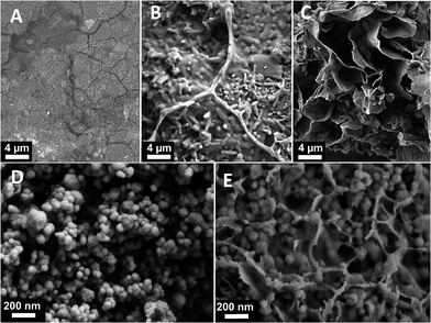
Concrete is a heterogeneous mixture of metal oxides.28 However, many standard methods consider concrete on meso and microscopic scale to be structurally uniform.29 Here we introduce polyacrylic acid network30 to introduce defects and dislocations into concrete network. In this way we construct supramolecularly bonded network of dislocations and we find formation of struts (Fig. 1B) in concrete mixture. Such strut formation leads to an enhancement of compressive and thermal strength of the defect-induced network.31–34 As we incorporate urea (U) as another supramolecular synthon, (Scheme 1) this initiates non-covalent interaction of urea with PAA and because of the presence of five hydrogen bonding sites in the synthons, a complex scaffold type network is observed35,36 (Fig. 1C). This further enhances the compressive and thermal strength of the complex network. We take a step further to incorporate metal oxide nanoparticles (TiO2 and ZrO2) inside the scaffold network to act as thermal resistivity enhancer in the network. It has been shown in various studies that in case of solid composite materials containing nano-sized particles, thermal resistance can be enhanced by incorporating smaller sized particles.37,38 This effect can be explained in the light of interfacial thermal resistance. As the particles become smaller their surface to volume ratio increases resulting higher interfacial thermal resistance. Phonon diffuse mismatch model suggests that an interface composed of two dissimilar materials provides better thermal resistance than two similar materials.39 This is why a composite material is expected to show better thermal resistance than virgin material.
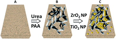 | ||
| Scheme 1 (A) Concrete matrix, (B) formation of scaffolds on addition of urea and PAA and (C) incorporation of ZrO2 and TiO2 nanoparticles inside scaffolds. | ||
We observe TiO2 and ZrO2 nanoparticles (NPs) embedded inside the scaffolds formed by PAA network (Fig. 1D). The defects caused by PAA of the concrete composite network leads to higher compressive strength whereas, TiO2 and ZrO2 nanoparticles added to the thermal stability of the system. Scheme 1 represents the formation of scaffolds and nanoparticles embedded inside scaffolds.
Now we describe how we get these results in our laboratory.
Experimental section
Ordinary standard portland cement (OPC) is used as received. Acrylic acid and urea were purchased and used as obtained from Merck chemicals. ZrO2 nanoparticles (<100 nm) and TiO2 nanoparticles (<30 nm) were purchased from Sigma Aldrich. Locally available natural sand is used as fine aggregate.Synthesis of polyacrylic acid (PAA)
Polyacrylic acid is synthesized as per our previously published paper.30 60 g deionized water and 2 g sodium hydrogen sulfite are added into a reactor and stirred until dissolved. The reactor then is slowly heated in an oil-bath and temperature is raised to 60 °C. Afterwards, a mixture of 20 g acrylic acid, 0.2 g ammonium peroxydisulphate and 20 mL deionized water is mixed and fed into the reactor by adding the whole mixture drop by drop over 40 minutes. The solution is stirred at 60 °C for another 1.5 hours. Later on, the reactor is cooled and the PAA so obtained is used for further experiments as described in the text.Preparation of concrete mixtures
A series of concrete mixtures have been prepared in the laboratory trials with various compositions as specimens. All the mixtures are consisting of natural aggregates, cement and water. The water to binder ratio for all mixtures was set at 0.40. The aggregates for the mixtures consisted of a combination of crushed basalt and of fine sand, with 30 wt% of sand. The binder content of all mixtures was 450 kg m−3.Synthesis of defect induced networks
To synthesize defect induced networks of concrete we have taken a 4![[thin space (1/6-em)]](https://www.rsc.org/images/entities/char_2009.gif) :
:![[thin space (1/6-em)]](https://www.rsc.org/images/entities/char_2009.gif) 1 volume by volume ratio of the additive with concrete. A composition of the additives is mentioned in Table 1.
1 volume by volume ratio of the additive with concrete. A composition of the additives is mentioned in Table 1.
| Sample number | PAA (μmol) | Urea (mmol) | ZrO2 NP (mmol) | TiO2 NP (mmol) |
|---|---|---|---|---|
| 1 | 14.4 | — | — | — |
| 2 | 7.2 | 6.25 | — | — |
| 3 | 7.2 | 3.33 | 1.8 | — |
| 4 | 7.2 | 2.5 | 1.4 | 1.625 |
Spectroscopy and microscopy experiments
A LABRAM HR800 Raman spectrometer is employed using the 633 nm line of a He–Ne ion laser as the excitation source to analyse the sample. SEM (Scanning Electron Microscopy) images are acquired by a Zeiss Sigma microscope.X-ray diffraction experiments
The XRD patterns were obtained by Rigaku mini flex II, Japan, using CuKα radiation having an incident wavelength of 1.541 Å operating under a voltage of 30 kV and a current of 50 mA. The scan rate was 12° min−1.Determination of thermal resistivity
To check the thermal resistivity of the samples, blocks have been they are exposed to oxyacetylene flame containing oxygen pressure of 3.03 N m−2 and acetylene pressure of 4.14 × 10⁻² N m−2 to make a hole through of fixed radius and the exposure time is noted. Thermal resistivity for each sample is calculated by finding out the heat flow across a given thickness of the sample. Average of five values from each specimen has been considered. Detailed procedure of calculation of thermal resistivity is mentioned in results and discussions section.Results and discussions
Formation of ‘dislocations’/struts and scaffolds and effects on complex structure thereof
We have shown earlier that supramolecular interaction can be used to induce gelation via cross-linking between supramolecular STAGs like PAA with urea, guanidine, and tartaric acid.30 Here we proceed on to the next step where we have used high alkalinity of concrete media to induce enormous supramolecular cross-linking among oligomeric and polymeric PAA. Uniform concrete mixture contains various metal oxide particles and sand particles of large dimension; however the structure is uniform in the length scale of micrometers as seen in SEM image given in Fig. 1A. Addition of PAA into concrete mixture produces strut like structure, as evidenced from SEM image (Fig. 1B). These struts can be taken as defects. Introduction of urea into the media results in the formation of scaffolds into the system, which emerges into a network of scaffolds at certain concentration of urea, as seen in the SEM (Fig. 1C).We believe this is due to the possibility of supramolecular stacking of urea units in the network to form scaffolds. Further addition of TiO2 and ZrO2 NPs results in incorporation of inside the network of the scaffold (Fig. 1E).
We now explain these observations. First we explain the formation of struts with the addition of PAA to concrete. Concrete media is highly alkaline. Such a high pH is due to the formation of metal hydroxides, specially Ca(OH)2 inside concrete media by the reaction of water with metal oxides present in cement. Alkaline media of concrete is responsible for the deprotonation of some of the carboxylic acid groups to form carboxylates when PAA is added into concrete media. These carboxylates can interact very strongly with the protons of the remaining carboxylic acid groups resulting supramolecularly bonded network in the form of struts (Fig. 1B). We propose these struts inside concrete acts as dislocations or defects in the otherwise structurally uniform system of concrete (Fig. 1A). Addition of urea in the system serves to provide the system with a hydrogen bonding scaffold. Since urea has five hydrogen-bonding sites and is known to form supramolecular scaffolds, in our concrete system we observe addition of urea results in the formation of the scaffolds inside the system. Increased concentration of urea enhances number of scaffolds and 9.3% (w/w) of urea leads to the formation of a network of scaffolds spreading all over the concrete network (Fig. 1C).
If we now focus on the structural transition from concrete to concrete with PAA and U, the following picture emerges. Concrete without any additive is a uniform system on microscopic (μm) length scale. Addition of PAA introduces struts in the system. We consider these struts as defects or dislocations in the system. Addition of urea creates extended network of scaffolds. In our view, addition of urea leads to the propagation of defects as an extended network. Question arises: what might be the direct consequence of such structural transitions on the strength or more precisely on the compressive strength of the concrete?
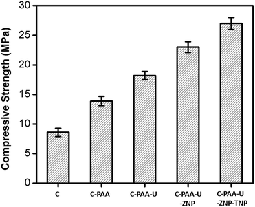
Comparison of compressive strength of all the samples is shown in Fig. 2. Concrete, without any additive shows a compressive strength of 8.6 MPa. The compressive strength is increased to be 13.9 MPa as soon as we include dislocation in the form of struts by adding PAA in the alkaline media. This indeed signifies that formation of struts in the system by supramolecular interactions acting as dislocations enhances the compressive strength of the system. Further addition of urea leads to further formation of scaffolds and thus more dislocations. Consequently the compressive strength increases to 18.2 MPa. To provide additional thermal resistance we have introduced ZrO2 and TiO2 nanoparticles in the system, along with urea and PAA. Interestingly, we observe that their introduction increases the compressive strength as well to 27 MPa.
We believe such observation of improved compressive properties of the defect induced networks can be explained in the light of distribution of stress per unit area. Applied external stress is distributed over the whole network containing more dislocations resulting in less stress per unit area than the starting concrete matrix without dislocations. As the number of dislocations increases, there is more division of stress which enables the system to withstand more external stress. In other words, as the number of dislocations increases the effective stress (force per unit area) gets reduced due to ‘branching off’ of the applied external stress. Consequently the net stress felt by the concrete is low. Higher the extent of dislocations or higher the number of dislocations, (concrete with PAA), higher the network of dislocations (concrete with PAA-urea), lesser is the effective stress on the concrete and hence higher is the concrete's ability to withstand stress. Thus greater is its compressive stress. Consequently, concrete with networks of defects and scaffolds having PAA and urea has highest compressive strength of 18.2 MPa followed by compressive strength of concrete with PAA alone having a compressive strength of 13.9 MPa. It is in turn much higher than that of concrete alone (8.6 MPa) without any dislocations. We also observe that when the NPs go inside the concrete scaffold with PAA and urea they increase the compressive strength further to 27 MPa due to usual and reported NP impregnation effect.40
In addition to that we believe the network of TiO2 and ZrO2 nanoparticles along with PAA scaffolds alter their adjacent environment and finally, the nanoparticles are more evenly distributed and hydrated, which result in higher fracture energy inherent in the cement phase.27
Now another question emerges. Since we know that extent of dislocations/defects influence the compressive strength of the concrete, can we control the extent to which such dislocations are introduced? More precisely, is it possible to control the length of PAA struts for instance by changing PAA concentration? Does such control in turn also influence the strength of the concrete as well? To do so, we change the extent of PAA addition along with urea in concrete.
We now look into the formation of scaffold networks induced by addition of PAA to regulate the strut length. We observe that for a constant concentration of urea if we increase the concentration of PAA, scaffold formation starts (Fig. 3A). On increasing the amount of PAA, a network of scaffold is formed. Fig. 3B–E depicts the situation where network formation takes place with increasing PAA. We also observe that as a function of PAA concentration, the length of scaffold network increases gradually. We have also quantified the length of scaffold formation as a function of amount of PAA for a given urea concentration (Fig. 4). We observe that on increasing PAA concentration keeping urea constant, the length of scaffold increases, and so does the compressive strength (Fig. 4B). The increase in the length of scaffolds with PAA amount verifies our proposition of supramolecular network formation between urea and PAA which in turn help to distribute externally applied stress throughout the network. Such redistribution of stress in turn leads to the enhancement of compressive strength of the concrete systems.
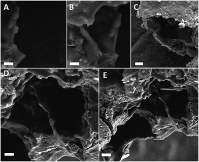 | ||
| Fig. 3 (A–E) Increased scaffold length with increase in concentration of PAA for a fixed U concentrations, scale bar represents 2 μm in all images. | ||
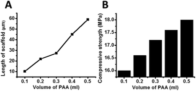 | ||
| Fig. 4 (A) Quantification of scaffold length with variation of PAA volume at fixed U amount, (B) comparison of compressive strength of concrete systems with variation of PAA volume. | ||
We observe the length of the PAA strut bears a linear relation with the compressive strength of the concrete. Hence in short, we are able to perform four functions simultaneously.
(1) We can introduce defects/dislocations controllably.
(2) We can control the length scale of these dislocations.
(3) By introducing defects/dislocations and controlling the length scales we can enhance strength of the concrete.
(4) Further introducing NPs we can enhance the concrete strength further significantly. We now describe this last step, in detail.
On addition of TiO2, ZrO2 nanoparticles
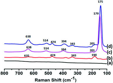
We have embedded ZrO2 (ZNP) and TiO2 nanoparticles (TNP) into the network structure. The stabilization of nanoparticles inside the scaffolds, we believe is responsible for incorporation inside the scaffold network without any external influence. Fig. 1D depicts ZrO2 and TiO2 nanoparticles in concrete matrix in absence of PAA and urea. Fig. 1E shows ZrO2 and TiO2 nanoparticles seated inside scaffolds formed by PAA and urea.Nanoparticle incorporation has been confirmed by scanning Nanoparticle incorporation has been confirmed by scanning electron microscopy (Fig. 1D and E), Raman spectroscopy (Fig. 5) and powder X-ray diffraction analysis (Fig. 6). Raman spectra of concrete does not show any significant peak, whereas doped ZrO2 concrete exhibits band at 190, 343, 474 and 635 cm−1, corresponding to Ag, Bg, Ag and 2Ag modes of the NPs (Fig. 5). In case of TiO2 doped concrete, Raman bands are observed at 149 (Eg), 201 (Eg), 394 (B1g), 514 (A1g & B1g) and 638 (Eg) cm−1. We have used a Raman spectrophotometer attached with microscope by which we hit the laser beam selectively on scaffolds instead of any random area. These allowed Raman bands are thus indicative of incorporation of ZrO2 and TiO2 nanoparticles inside concrete media.
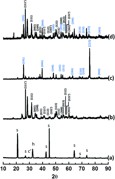
XRD patterns also confirm the incorporation of nanoparticles (Fig. 6). Fig. 6a signifies XRD data of concrete where s, c′ are h are corresponding reflections for SiO2, CaCO3 and Ca(OH)2 respectively. Broad peaks observed for TiO2 and ZrO2 are indicative of nanoparticles (Fig. 6b–d). The results are in agreement with Raman spectral data.
Measurements of thermal resistivity of the specimens
Thermal resistivity of a specimen is the temperature difference between two defined surfaces of the material at steady state which induces a unit heat flow rate through a unit area. In present case, to measure the thermal resistivity of the specimens we have prepared blocks (4 cm × 3 cm × 1 cm) of all specimens using general concrete block preparation technique. Then the blocks were exposed to oxy-acetylene flame to make a hole of fixed diameter into them.To measure the thermal resistivity, we first calculate the thermal conductivity (λ) of the specimens exposed to oxy-acetylene flame conductivity using eqn (1).
| λ = (Q/A)/(ΔT/ΔL) | (1) |
Now, amount of heat passing through the specific cross section can be expressed as, Q = mcθ, where m = mass of the cross sectional area, c = specific heat of the specimen and θ = temperature of the heat source.
As we now know the value of thermal conductivity (λ) of a specimen, thermal conductivity per unit second is κ = λ/t; (t is time of heat flow in second). So, thermal resistivity per unit second, ρ = 1/κ.
‘θ’ is considered as 3273 K for oxy-acetylene flame.41 ‘t’, here is the time needed in second to make a hole through the specimen block using the flame. After exposure, the cross section of the hole made is considered as ‘A’ which is 0.0007 m2. Mass of the block of equal volume of hole is taken as ‘m’. Specific heat for each specimen is taken from literature and tabulated in Table 2. In case of specific heat of composite materials, specific heat calculation experimentally is beyond our scope, so simple additive rule is applied (Table 3). ΔT = temperature difference between two surfaces of the block = (3273–298) K = 2974 K. ΔL = 0.01 m, the height of the concrete block.
Above thermal resistivity values clearly indicate that in addition to enhancing mechanical strength, nanoparticles play important role in the matter of enhancement of thermal strength of the concrete. TiO2 and ZrO2 NPs increase the thermal resistivity of the concrete by a factor of few folds implying enhancement in thermal resistance. With inclusion of ZNP, thermal resistivity value reaches to 4.2 W−1 m K whereas presence of both ZNP & TNP, the value is 5.1 W−1 m K. It is worth noting that introduction of defects (struts) also increases thermal resistivity hence thermal strength of the samples. We see that inclusion of PAA leads to increase in thermal resistivity value from 0.55 W−1 m K (only concrete) to 1.38 W−1 m K. Introduction of urea in system results ρ value to 2.5 W−1 m K. Results of thermal resistivity measurement have been shown in Table 4 & in Fig. 7.
| Specimens | Q (J) | λ (J m−1 K−1) | t (sec) | κ (W m−1 K−1) | ρ (W−1 m K) |
|---|---|---|---|---|---|
| C | 19![[thin space (1/6-em)]](https://www.rsc.org/images/entities/char_2009.gif) 480 480 |
93.57 | 51 | 1.83 | 0.55 |
| C-PAA | 18![[thin space (1/6-em)]](https://www.rsc.org/images/entities/char_2009.gif) 862 862 |
90.54 | 125 | 0.72 | 1.38 |
| C-PAA-U | 22![[thin space (1/6-em)]](https://www.rsc.org/images/entities/char_2009.gif) 916 916 |
109.99 | 156 | 0.36 | 2.5 |
| C-PAA-U-ZNP | 19![[thin space (1/6-em)]](https://www.rsc.org/images/entities/char_2009.gif) 656 656 |
94.35 | 385 | 0.24 | 4.2 |
| C-PAA-U-ZNP-TNP | 18![[thin space (1/6-em)]](https://www.rsc.org/images/entities/char_2009.gif) 223 223 |
87.47 | 421 | 0.2 | 5.1 |
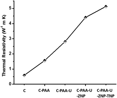 | ||
| Fig. 7 Comparison of thermal resistivity of the samples, thermal resistivity increases with inclusion of defects/dislocations. | ||
Infrared (IR) spectroscopic investigations
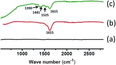
Formation of scaffolds also has also been shown from infrared (IR) spectroscopic investigations. We have performed IR spectroscopic analysis for all the samples. The results are shown in Fig. 8. For easy understanding of the spectra, spectrum of concrete is subtracted from each of the spectrum. Concrete with PAA shows a band at 1615 cm−1 which signifies COO− asymmetric stretching in the network coming from PAA. As soon as we added urea into the system new spectral bands were visible at 1525, 1441 and 1390 cm−1 which were due to N–H deformation, in plane O–H bending and C–H bending modes, respectively. Appearing of such spectral modes along with lowering in intensity of COO− asymmetric stretching mode in PAA is indicative of supramolecular interaction between PAA and urea which leads to formation of scaffolds inside concrete network.Conclusions
To summarize, we have shown how we could introduce dislocations/defects in the form of supramolecularly bound PAA and urea based scaffold networks and metal oxide nanoparticles. By virtue of their supramolecular bonding sites, polyacrylic acid and urea create a network of struts. These struts act as dislocations in otherwise uniform concrete structure. The struts in turn increase the strength of concrete. The length of these struts can also be controlled. Such a control has also been shown to influence the strength of the concrete. In short we show that defects/dislocations in the form of struts distribute the external applied stress and thereby reduce the effective stress for unit matrix area. Consequently higher the extent of dislocation, larger is the capacity of the concrete matrix to withstand externally applied stress, higher is its mechanical strength. We further incorporated ZrO2 and TiO2 nanoparticles inside scaffolds which enhance thermal resistivity of the concrete. ZrO2 and TiO2 nanoparticles are responsible for enhanced thermal resistivity of the composite concrete. The work could have practical applications in making of concrete with enhanced compressive and thermal strength.Acknowledgements
Thanks are due to Santu Das and Sourav Kumar for their collaboration with the work. SB thanks UGC for fellowship.References
- Z.-W. Qu and G.-J. Kroes, J. Phys. Chem. C, 2007, 111, 16808–16817 CAS.
- N. K. Sharma, R. Misra and S. Sharma, Comput. Mater. Sci., 2014, 90, 130–136 CrossRef CAS.
- Z. Li, P. Dharap, P. Sharma, S. Nagarajaiah and B. I. Yakobson, J. Appl. Phys., 2005, 97, 074303 CrossRef.
- J. Y. Huang, F. Ding and B. Yakobson, Phys. Rev. Lett., 2008, 100, 035503 CrossRef CAS PubMed.
- X. Zhang, K. Jiao, P. Sharma and B. Yakobson, J. Mech. Phys. Solids, 2006, 54, 2304–2329 CrossRef CAS.
- E. Cerda, S. Chaieb, F. Melo and L. Mahadevan, Nature, 1999, 401, 46–49 CrossRef CAS.
- A.-L. Barabási, R. Albert and P. Schiffer, Phys. A, 1999, 266, 366–371 CrossRef.
- R. Grantab, V. B. Shenoy and R. S. Ruoff, Science, 2010, 330, 946–948 CrossRef CAS PubMed.
- R. Baughman and D. Galvao, Chem. Phys. Lett., 1995, 240, 180–184 CrossRef CAS.
- R. H. Baughman, S. Stafström, C. Cui and S. O. Dantas, Science, 1998, 279, 1522–1524 CrossRef CAS PubMed.
- R. H. Baughman and D. S. Galvão, Nature, 1993, 365, 735–737 CrossRef CAS.
- A. Nazari, R. Sh, R. Sh, S. F. Shamekhi and A. Khademno, Am. J. Sci., 2010, 6, 6–9 Search PubMed.
- D. Bui, J. Hu and P. Stroeven, Cem. Concr. Compos., 2005, 27, 357–366 CrossRef CAS.
- G. Ye, X. Liu, G. De Schutter, A.-M. Poppe and L. Taerwe, Cem. Concr. Compos., 2007, 29, 94–102 CrossRef CAS.
- S. K. Rejeb, Cem. Concr. Res., 1996, 26, 585–592 CrossRef.
- Y. Shao, Z. Zhu and A. Mirmiran, Cem. Concr. Compos., 2006, 28, 959–968 CrossRef CAS.
- B. Sabir, S. Wild and J. Bai, Cem. Concr. Compos., 2001, 23, 441–454 CrossRef CAS.
- M. Jalal, A. A. Ramezanianpour and M. K. Pool, Composites, Part B, 2013, 55, 324–337 CrossRef CAS.
- A. Nazari and S. Riahi, J. Compos. Mater., 2010, 45, 1181–1188 CrossRef.
- I. S. Neira, Y. V. Kolen’ko, K. P. Kommareddy, I. Manjubala, M. Yoshimura and F. Guitián, ACS Appl. Mater. Interfaces, 2010, 2, 3276–3284 CAS.
- A. Nazari and S. Riahi, Mater. Sci. Eng., A, 2011, 528, 1183–1191 CrossRef.
- A. Nazari and S. Riahi, Mater. Sci. Eng., A, 2011, 528, 1173–1182 CrossRef.
- M. Stefanidou and I. Papayianni, Composites, Part B, 2012, 43, 2706–2710 CrossRef CAS.
- C. Plassard, E. Lesniewska, I. Pochard and A. Nonat, Langmuir, 2005, 21, 7263–7270 CrossRef CAS PubMed.
- A. A. Zolotarev, A. I. Lushin, N. A. Charykov, K. N. Semenov, V. I. Namazbaev, V. A. Keskinov and A. S. Kritchenkov, Ind. Eng. Chem. Res., 2013, 52, 14583–14591 CrossRef CAS.
- I. F. Sáez del Bosque, S. Martínez-Ramírez and M. Blanco-Varela, Ind. Eng. Chem. Res., 2013, 52, 11866–11874 CrossRef.
- D. Feng, N. Xie, C. Gong, Z. Leng, H. Xiao, H. Li and X. Shi, Ind. Eng. Chem. Res., 2013, 52, 11575–11582 CrossRef CAS.
- F. De Larrard, Concrete mixture proportioning: a scientific approach, CRC Press, 1999 Search PubMed.
- M. Hernández, J. Anaya, M. Izquierdo and L. Ullate, Ultrasonics, 2002, 40, 217–221 CrossRef.
- F. F. Xue, D. D. Yuan, A. Sahasrabudhe, S. Biswas, P. Wang, X.-Y. Tang, D. Chen, R. Yuan and S. Roy, New J. Chem., 2012, 36, 2541–2548 RSC.
- J. Y. Huang, F. Ding and B. I. Yakobson, Phys. Rev. Lett., 2008, 100, 035503 CrossRef CAS PubMed.
- P. Zhang, L. Ma, F. Fan, Z. Zeng, C. Peng, P. E. Loya, Z. Liu, Y. Gong, J. Zhang, X. Zhang, P. M. Ajayan, T. Zhu and J. Lou, Nat. Commun., 2014, 5, 3782 CAS.
- W. Wang, C. Shen, S. Li, J. Min and C. Yi, AIP Adv., 2014, 4, 031333 CrossRef.
- A. Zandiatashbar, G.-H. Lee, S. J. An, S. Lee, N. Mathew, M. Terrones, T. Hayashi, C. R. Picu, J. Hone and N. Koratkar, Nat. Commun., 2014, 5, 3186 Search PubMed.
- Z. Dong, Q. Luo and J. Liu, Chem. Soc. Rev., 2012, 41, 7890–7908 RSC.
- S. George, S. Lipstman, S. Muniappan and I. Goldberg, CrystEngComm, 2006, 8, 417–424 RSC.
- A. Khitun, A. Balandin, J. L. Liu and K. L. Wang, J. Appl. Phys., 2000, 88, 696–699 CrossRef CAS.
- A. G. Every, Y. Tzou, D. P. H. Hasselman and R. Raj, Acta Metall. Mater., 1992, 40, 123–129 CrossRef CAS.
- H. Wang, Y. Xu, M. Shimono, Y. Tanaka and M. Yamazaki, Mater. Trans., 2007, 48, 2349–2352 CrossRef CAS.
- A. Nazari and S. Riahi, Mater. Res., 2010, 13, 551–556 CrossRef CAS.
- G. M. Song, S. B. Li, C. X. Zhao, W. G. Sloof, S. van der Zwaag, Y. T. Pei and J. T. M. De Hosson, J. Eur. Ceram. Soc., 2011, 31, 855–862 CrossRef CAS.
- J. K. Kim, K. H. Kim and J. K. Yang, Comput. Struct., 2001, 79, 163–171 CrossRef.
- C. O. M'Bareck, Q. Nguyen, M. Metayer, J. Saiter and M. Garda, Polymer, 2004, 45, 4181–4187 CrossRef.
- A. Mehrez, A. H. H. Ali, W. Zahra, S. Ookawara and M. Suzuki, Int. J. Chem. Eng. Appl., 2012, 3, 347–353 CAS.
- U. Rea, T. McKrell, L.-W. Hu and J. Buongiorno, Int. J. Heat Mass Transfer, 2009, 52, 2042–2048 CrossRef CAS.
- M. Saeedian, M. Mahjour-Shafiei, E. Shojaee and M. Mohammadizadeh, J. Comput. Theor. Nanosci., 2012, 9, 616–620 CrossRef CAS.
| This journal is © The Royal Society of Chemistry 2016 |

