
Shear-force-dominated dual-drive planetary ball milling for the scalable production of graphene and its electrocatalytic application with Pd nanostructures†
G. Rajendra Kumarabc,
K. Jayasankar*ac,
Sushanta K. Dasac,
Tapan Dashac,
Ajit Dashac,
Bikash Kumar Jena*ac and
Barada Kanta Mishraac
aCSIR-Institute of Minerals and Materials Technology, Bhubaneswar-751 013, India. E-mail: jayasankar_met@yahoo.co.in
bDepartment of Electrical and Computer Engineering, Pusan National University, San 30, Jangjeong-Dong, Gumjeong-Ku, Busan-609 735, South Korea
cAcademy of Scientific & Innovative Research, New Delhi-110001, India
First published on 29th January 2016
Abstract
The exceptional properties of graphene-based derivatives have governed numerous research fields in recent years. The scaled up and reliable production of high-quality graphene is still a challenging task. This work presents an efficient and low-cost approach for the mass production of high-quality graphene (50 g scale batch) through the dual-drive planetary ball milling of graphite with a dicarboxylic acid. The dimensional changes of graphite were determined from the diffraction pattern of the (002) plane at different milling times and the unique signature of graphene noticed in the Raman spectra. Transmission electron microscopy clearly revealed the existence of single and bilayer graphene sheets. Non-destructive exfoliation was evidenced by the surface binding states of the C 1s core level spectra. The as-synthesized graphene was utilized as the catalytic support for formic acid fuel cell applications. Graphene supported palladium nanocomposites were prepared, and the electrocatalytic activity towards formic acid oxidation was explored. The cyclic voltammogram of the graphene–palladium nanocomposite reveals that the onset potential for formic acid oxidation is −0.1 V with a prominent oxidation peak at 0.263 V.
1. Introduction
The discovery of new materials leads to the most exciting and fruitful periods of scientific and technological research. New materials present new opportunities to review old problems as well as solve new ones. The recent discovery of graphene, a single layer of graphite, brought about such an exciting period of research and technological interest.1 Graphene is a two-dimensional building block of covalently bonded sp2 hybridized carbon and allotropes of other carbon-based materials. It can be rolled into one-dimensional nanotubes, stacked into three-dimensional graphite, or wrapped into zero-dimensional fullerene. The interesting electronic, optical, mechanical and thermal properties have resulted in the great success of graphene for several applications. The variety of technological applications based on graphene requires the production of graphene on a large scale.A large number of methods have been proposed to produce graphene with high quality. The present approaches fail to produce graphene on a large enough scale. Micromechanical cleavage is suitable for high-quality graphene sheets, but the low productivity of this method makes it incompatible for large-scale usage. The methods involving the exfoliation of graphene in solution can produce large-scale materials and cause the process of breaking the stacking force between the graphitic layers. This can be carried out mainly through two major approaches: the sonication of graphite in solvent or chemical functionalization (e.g., graphene oxide). The sonication exfoliation method aids the experimental preparation of graphene sheets remarkably. However, continuous sonication is required to give a higher yield of graphene and excessive sonication can lead to the destruction of graphene.2–5 The chemical functionalization of graphite (e.g. graphite oxide) is an efficient approach for the bulk production of graphene sheets at low cost. But, the process requires the contribution of hazardous strong oxidizing (e.g. H2SO4/KMnO4) and reducing reagents.6
Simple planetary ball milling has been employed for the non-destructive and large-scale production of graphene sheets in recent years.7 However, it is difficult to exfoliate graphite through dry ball milling due to the plate-like structure of the graphite layers. The wet ball milling of graphite with organic solvents is a possible method for the preparation of good quality graphene, but the exfoliation efficiency needs to be improved.8 The production of graphene through the ball milling of graphite with dry ice or melamine was demonstrated.9 The introduction of oxalic acid as a reductant for the preparation of high-quality graphene from graphene oxide (GO) was also demonstrated.10 The CVD process offers large scale graphene production but the usage of toxic chemicals may generate hazardous waste and poisonous gases. This method is complicated and has a high production cost.11 Accordingly, it is a necessity to develop a simple approach that is environmentally friendly and allows for scalable graphene production at low cost.
In this work, we employed the shear-force-dominated milling of graphite with oxalic acid for scaled up graphene production (50 g per jar) at an extremely low cost. The shear force and mill assisting agent plays a vital role in non-destructive graphene production during the ball milling process. The dynamics of shear force milling are measured using the percentage of the critical speed that depends on the gyrating and jar speed in the dual-drive ball milling system. The shear dominated milling is optimized in terms of the rotation speed of the vials and shaft holding the vials, ball to powder weight ratio, milling time, type and size of grinding medium and milling container. The critical speed is the key factor in deciding the shear and impact energy between the balls and powder. The critical speed is estimated using eqn (1) and tabulated in the ESI.†
Dual-drive ball milling can produce 50 g of graphene powder (in a single jar) and 200 g of graphene powder in a unique milling cycle. The main advantages of dual-drive ball milling compared to other graphene preparation techniques are the simple process, cost effectiveness, and large scale production. The inevitable introduction of metal impurities on the surface of the graphene sheets from the balls, the energy gradient between the balls and powder, and inhomogeneous crystallite (size and shape) formation with impurities and grain boundaries are the disadvantages of this method. This work is mainly focused on the development of shear-force-dominated ball milling for scalable and non-destructive graphene production and investigating the quality of graphene using complementary characterization techniques, along with the utilization of a Pd nanostructure as an electrocatalyst for the formic acid oxidation process.
2. Experimental
2.1 Raw materials
Graphite flakes (product no. 332461, Sigma-Aldrich) and oxalic acid dihydrate (ACS reagent, product no. 247537, Sigma-Aldrich) were used.2.2 Synthesis of graphene
In a typical procedure, 50 g of graphite flakes and 80 g of oxalic acid (OA) were placed into a stainless steel jar (2500 ml volume) containing 10 mm diameter stainless steel balls, which were used as the grinding medium. Low diameter stainless steel balls were utilized to increase the impact and shear energy between the balls and powder, and to have a low dimensional interaction with the graphite layers. Initially, the dual-drive ball milling was executed at three different critical speeds (40%, 70%, and 98%), but the critical speed of 40% offers efficient exfoliation with less defects than 70% and 98%. Accordingly, the optimized critical speed of 40% was adopted for graphite exfoliation using shear force ball milling. The milling was carried out for up to 20 h and the rest time was one hour per cycle. Then, the milled graphite was treated with 1 M hydrochloric acid (HCl) to acidify the carboxylates and to remove the iron impurities from the milling jar. Then, the mixture was washed with distilled water several times until the pH was neutral. The mixture was filtered and subjected to heat treatment at 600 °C under an argon atmosphere for an appropriate time interval. Finally, as-prepared graphene was stored for future use.2.3 Synthesis of graphene–Pd nanocomposites
3 mg of the as-prepared graphene powder was added to 30 ml of DMF and dispersed using sonication for 10 min and stirred for a further 30 minutes. Then 0.6 ml of 50 mM PdCl2 was added to the graphene dispersed DMF solution and allowed to mix under stirring conditions. Then 0.6 ml of NaBH4 (50 mM) was added dropwise and the mixture was allowed to stir for 30 minutes. After, the sample was separated using centrifugation and washed properly to remove DMF and unreacted species. The sample was dried and kept in a desiccator for future use.2.4 Characterization
The X-ray diffraction (XRD) patterns of ball milled graphite were collected using a PANalytical X-ray diffractometer equipped with an Ni-filtered CuKα radiation source (λ = 1.54 Å). The radiation source operated at a generator voltage of 40 kV and current of 40 mA. The XRD data was recorded in the range of 20–40 (2θ), in a step scan mode with a step width of 0.05 and a time of 1 s per each step. Transmission electron microscopy (TEM) images were obtained using an FEI Tecnai G2 TEM operating at 200 kV. The specimens were prepared by dropping 2 μL of colloidal solution onto carbon-coated copper grids. The X-ray photoelectron spectroscopy (XPS) analysis was carried out on a Specs (Germany) X-ray photoelectron spectrometer. The high-resolution spectra were recorded using a 20 eV pass energy with Mg Kα 12![[thin space (1/6-em)]](https://www.rsc.org/images/entities/char_2009.gif) 586 eV radiation.
586 eV radiation.
2.5 Electrochemical measurements
The electrochemical analysis was performed using a two-compartment three-electrode cell with a glassy carbon working electrode (area = 0.07 cm2), a platinum wire as an auxiliary electrode and Ag/AgCl (3 M KCl) as a reference electrode. Cyclic voltammograms were recorded using a computer-controlled CHI660C electrochemical analyzer (CHI, USA). The as-synthesized materials were dispersed over a glassy carbon electrode with Nafion and dried prior to the electrochemical experiments.3. Results and discussion
3.1 Mechanism of graphite exfoliation using shear-force-dominated ball milling
The shear-force-dominated ball milling of graphite with oxalic acid was carried out under optimized critical speeds (40%, 70%, and 98%). In this process, the graphene sheet can be exfoliated layer by layer from graphite. The weak Van der Waals interactions between the graphitic layers may resist the graphene exfoliation. High energy ball milling typically generates impact and shear forces between the balls and powder. The impact force can overcome the Van der Waals forces of the graphite layers to deliver uncontrolled exfoliation in a destructive way (micromechanical cleavage using scotch tape).12 The shear force delivers an essential and controlled energy to diminish the Van der Waals interactions and encourage the relative motion between the graphitic layers for ease of exfoliation of the graphene sheets. The mill assisting agent (oxalic acid) provides great support for non-destructive exfoliation. The dehydrogenated oxalic acid (the reducing agent) possess a strong oxygen free radical that confines the carbonyl group to the edges of graphite. An additional fragmentation effect may occur during the exfoliation process when not carried out at the optimum critical speed. This effect may result in the inevitable inclusion of impurities and structural defects. The schematic representation of the mechanism3 is shown in Fig. 1.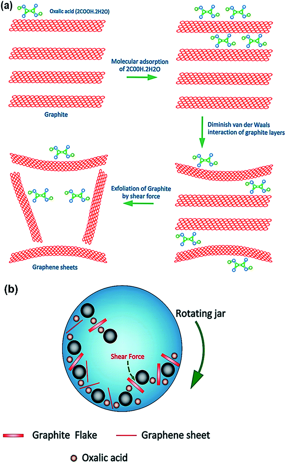 | ||
| Fig. 1 (a) Mechanism of graphite exfoliation through shear-force ball milling and (b) schematic representation of the ball milling of graphite with oxalic acid. | ||
3.2 Structural analysis of graphene sheets
The XRD patterns of milled graphite/oxalic acid after different milling times are shown in Fig. 2. The presence of the (002) diffraction peak confirms that the milled graphite has an ordered crystal structure.13–15 According to the JCPDS (03-065-6212), the diffraction pattern of graphite and milled graphite is dominated by the strong (002) plane at 26.6°.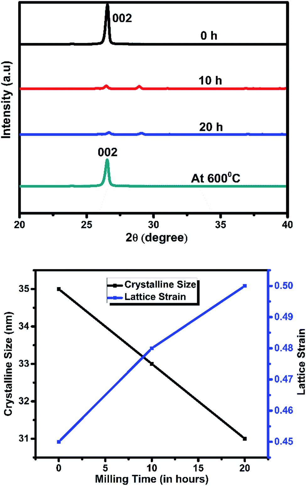 | ||
| Fig. 2 (a) XRD patterns of graphite and milled graphite/oxalic acid after different milling periods (0 h, 10 h, and 20 h) at 40% critical speed. (b) The crystalline size and strain calculation with respect to the milling time. | ||
The continuous decrease in the intensity of the (002) peak after 10 h and 20 h experiments indicates the reduction of the size and thickness of graphite. This observation supports the exfoliation of graphene from bulk graphite. After 20 h of milling, few peaks were left. Heat treatment diminishes the impurity peaks and increases the intensity of the (002) planes, which might be due to the agglomeration of graphene sheets. With increasing milling time, the (002) peak was shifted towards lower angles, suggesting the widening of the d002 spacing. The crystalline size gradually decreases with increasing strain according to the increase in milling time, which is depicted in Fig. 2.
3.3 Raman spectroscopy of graphene sheets
Raman spectroscopy is a powerful non-destructive tool for further estimating the thickness and purity of the as-prepared graphene. The Raman spectra of graphite, graphite milled for 20 h, milled graphite annealed at 600 °C and graphene prepared at different critical speeds are presented in Fig. 3a and b. For graphite, a G band (1570 cm−1), 2D band (2708 cm−1) and weak D band were observed. The graphite milled with oxalic acid for 20 h showed a strong D band at 1350 cm−1 that corresponds to the breathing modes of sp2 carbon atoms.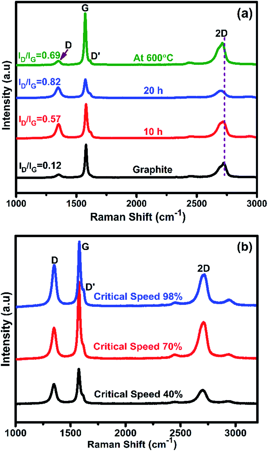 | ||
| Fig. 3 Raman spectra of ball-milled graphite/oxalic acid: (a) 10 hours, 20 hours and annealed at 600 °C and (b) at different critical speeds for 20 hours. | ||
The G peak that arises at 1580 cm−1 is the result of first-order scattering of the E2g mode of graphite and is related to the in-plane vibration of sp2 hybridized carbon–carbon bonds. The 2D band around 2700 cm−1 arises due to second phonon vibrations of sp2 carbon atoms.16 In this case, the 2D peak is quite broad and a D′ peak appears around the shoulder of the G peak at 1585 cm−1, which is characteristic of bilayer graphene sheets. This observation is well-matched with the previous report.5 The intensity ratio ID/IG of isolated graphene after 20 h is ∼0.57, which is much lower than the value of graphene chemically derived through the reduction of graphite oxide.
As expected, the D peak from the inside of an isolated graphene sheet has almost disappeared after heat treatment at 600 °C for 5 min. The ID/IG value of annealed graphene is ∼0.09 which indicates that heat treatment increased the quality of the material. The intensity ratio I2D/IG is calculated to be ∼0.41, which specifies the thickness of the graphene sheet.17–19 The critical speed is the most important parameter in the ball milling technique for getting a high quality graphene sheet. In this work, we attempted to perform the milling process of graphite with oxalic acid at different critical speeds of 40%, 70% and 98% for 20 hours.
Fig. 3b reveals that 40% critical speed shows better results than 98% and 70% critical speed in the dual-drive ball mill system. It can be deduced that the slow speed can efficiently exfoliate the graphene sheet from graphite with less defects. 98% and 70% critical speed cause faster grinding than 40% critical speed. At higher critical speeds, the exfoliation occurs efficiently but the defects are quite high. The purity of the material is calculated from the intensity ratio ID/IG and is ∼0.53 for 40%, ∼0.59 for 70% and ∼0.62 for 98% critical speed, respectively (Table S3†). The number of layers in the graphene sheet at different critical speeds was determined from the I2D/IG ratio presented in Table S3.†
3.4 Transmission electron microscopy (TEM) of graphene sheets
The TEM measurements were carried out to determine the degree of exfoliation and the morphology of the graphene sheets.20,21 The selected area (electron) diffraction (SAD) patterns were recorded to identify the crystal structures and measure the lattice parameters. The TEM images of graphite and the as-prepared graphene sheets and their corresponding SAD patterns are shown in Fig. 4. The pure graphite flakes are slightly transparent under the electron beam and the sheets are stacked irregularly. The SAD pattern of the graphite flakes clearly confirmed the polycrystalline nature of graphite (Fig. 4b). Fig. 4c shows that the exfoliated graphene sheets were quite transparent under the electron beam, suggesting the very small thickness of the graphene sheets. The single and bilayer graphene sheets were clearly visible in the TEM image.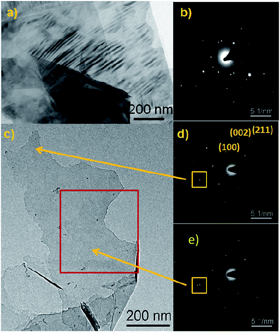 | ||
| Fig. 4 TEM images of (a) graphite, (b) corresponding SAD pattern (c) representative graphene sheets with the SAD patterns for (d) single and (e) bilayer graphene sheets. | ||
The corresponding SAD pattern confirmed the presence of single layer graphene, which is represented by a six point crystal system. Also, two sets of six point crystal systems that are closely arranged are observed. This validates that the sample might contain bilayer graphene sheets. This validates that the oxalic acid assisted exfoliation of graphite through shear milling is non-destructive and also provides a great platform for the mass production of high quality graphene sheets.22
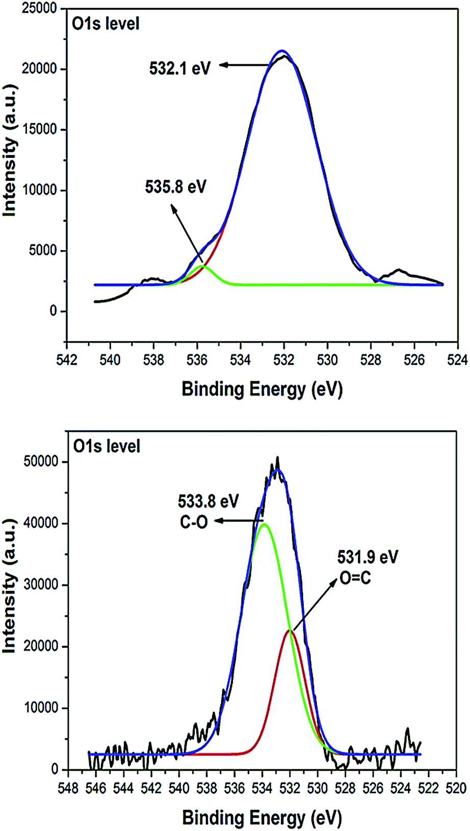
X-ray photoelectron spectroscopy (XPS) is a quantitative surface analysis technique that was used to identify the chemical composition and binding states of the as-prepared graphene sheet. Fig. 5 shows the C 1s core-level spectra of both graphite and graphene with the prominent C 1s peak appearing at 284.7 eV, which is assigned to the sp2 hybridized carbon atoms. The similar patterns of graphite and graphene reveal that the intrinsic structure of graphite remains largely intact during the milling treatment. It suggested that shear dominated ball milling doesn’t affect the intrinsic structure of the graphene sheet. The weak peak at 290.6 eV that corresponds to the π–π transitions of graphitic carbon appeared only in graphite. The peak at 287.5 eV is usually attributed to the C![[double bond, length as m-dash]](https://www.rsc.org/images/entities/char_e001.gif) O (carbonyl and carboxylic acid) groups of both graphite and graphene. The size of graphite was reduced during milling, which was confirmed by the change in the peak intensity, binding energy positions and atomic concentration of graphite and graphene. Fig. 6 represents the surface binding states of O 1s for graphite and graphene.
O (carbonyl and carboxylic acid) groups of both graphite and graphene. The size of graphite was reduced during milling, which was confirmed by the change in the peak intensity, binding energy positions and atomic concentration of graphite and graphene. Fig. 6 represents the surface binding states of O 1s for graphite and graphene.
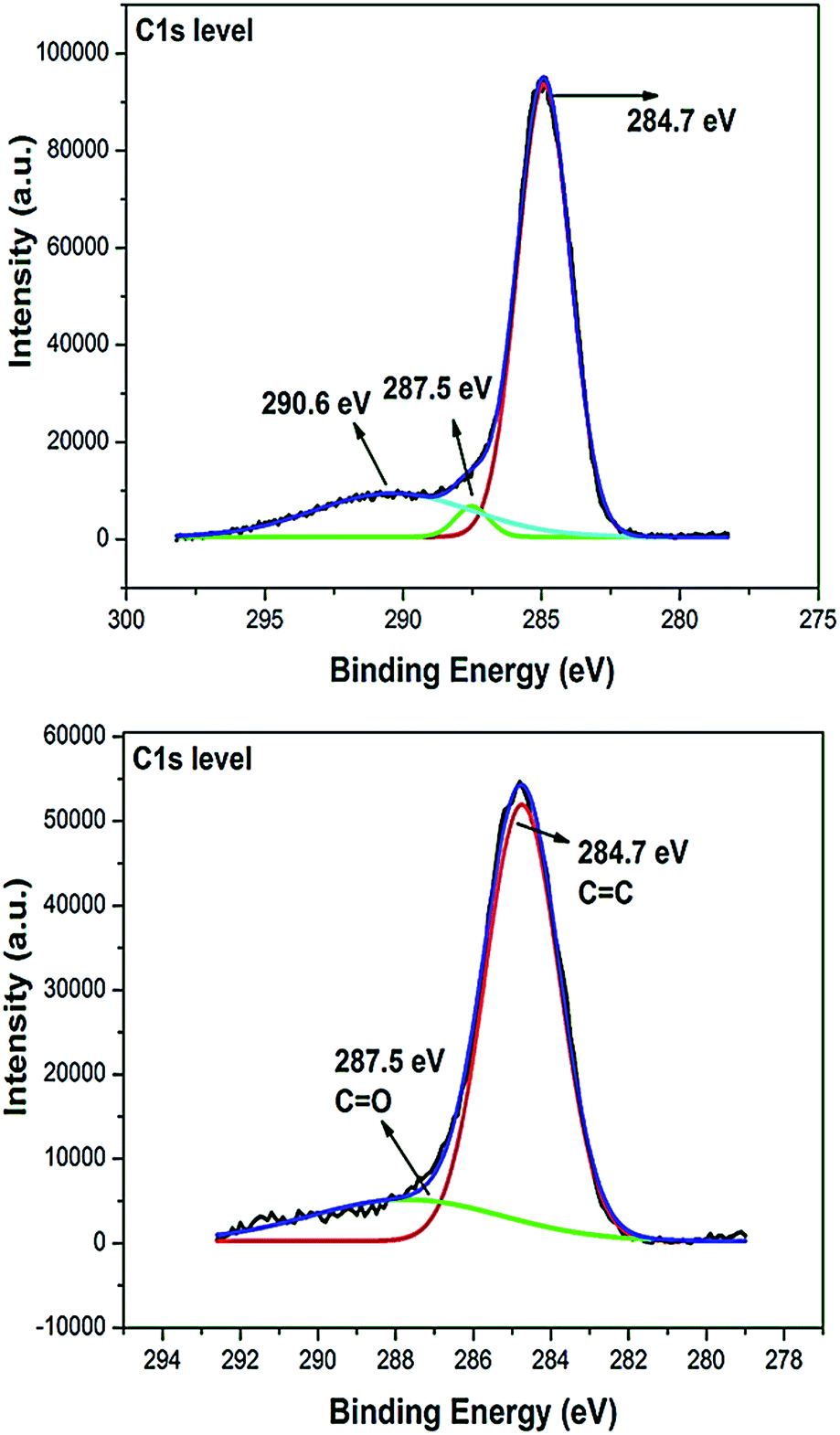 | ||
| Fig. 5 XPS spectrum showing the C 1s binding states of graphite and graphene. | ||
 | ||
| Fig. 6 XPS spectrum showing the O 1s binding states of graphite and graphene. | ||
A trace O 1s peak arises at 532.1 eV and 531.9 eV for graphite and graphene, which is assigned to the CO binding state. The peak located at 535.8 eV in graphite might be physically adsorbed water or oxygen from the addition of oxalic acid.23
3.5 Electrochemical studies on graphene–palladium nanocomposites
Graphene supported Pd nanocomposites were synthesized using a facile one step approach. The Pd precursor was dispersed with the as-synthesized graphene sheet and reduced to form Pd nanostructures on the graphene surface. TEM measurements were carried out to investigate the morphology of the Pd nanostructures grown on the graphene surface and are presented in Fig. 7. Here, we chose formic acid as the typical molecule for studying the electrocatalytic activity of the graphene–palladium nanocomposites. Interestingly, the tiny Pd nanostructures are well dispersed on the graphene support.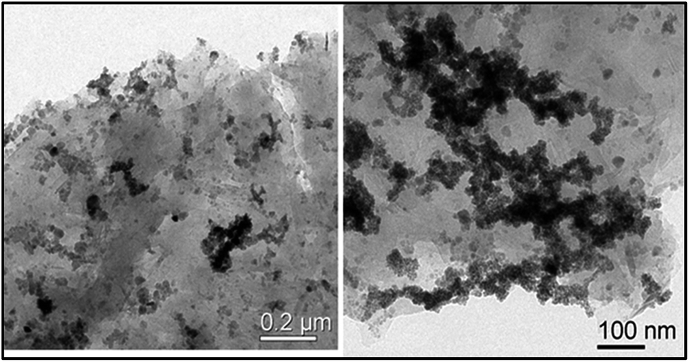 | ||
| Fig. 7 TEM images of graphene supported Pd nanostructures. | ||
The Pd nanostructures agglomerated on part of the graphene surface during the drying process. The electrochemical oxidation of formic acid is very much a useful process in the energy sector due to its potential energy related applications. Various hybrid catalysts have been prepared to enhance formic acid oxidation. It has been documented that Pt-based catalysts provided outstanding catalytic performance towards formic acid oxidation.
However, the Pt surface intensely adsorbs the CO species created as a reaction intermediate, which causes surface poisoning. Pd-based catalysts have been found to be efficient and possess superior performances for fuel cell applications because Pd is highly resistant towards CO poisoning. Therefore, the electrocatalytic performance of the as-synthesized graphene–Pd nanocomposites towards formic acid oxidation was explored (Fig. 8). A well-defined inverted V-shaped voltammogram with a prominent oxidation peak at 0.263 V was observed for the graphene–Pd nanocomposite modified electrode. The onset potential for formic acid oxidation is −0.1 V. The oxidation current has been normalized to the electro-active surface area of the graphene-supported Pd nanostructures. This surface area was determined from the columbic charge reduction of Pd oxide according to the reported value of 424 μC cm−2.21,24 The onset potentials of formic acid oxidation were calculated as −0.15 V and −0.49 V for the graphene–Pd composites obtained using a sonication exfoliation method25 and a modified Hummer method,26 respectively. The graphene based Pd nanocomposites prepared through ball milling show a comparable onset potential of −0.1 V and an oxidation peak at 0.263 V. Further efforts are underway to improve the quality of the graphene–Pd nanocomposites to deduce the effect of the substrate on the electrocatalytic activity towards formic acid for fuel cell applications.
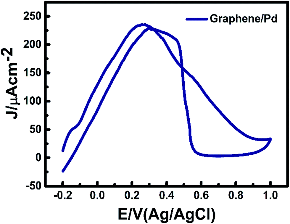 | ||
| Fig. 8 Cyclic voltammogram for the oxidation of formic acid (0.25 M) in 0.1 M HClO4. | ||
4. Conclusions
We employed simple shear-force-dominated planetary ball milling to prepare graphene on a large scale (200 g per cycle) with less structural defects. The optimized critical speed (40%) can efficiently exfoliate a graphene sheet from graphite, evidenced by Raman spectroscopic analysis. The onset potential for formic acid oxidation is −0.1 V with a prominent oxidation peak at 0.263 V. The graphene based Pd nanostructures show improved catalytic activity for formic acid oxidation which suggests that the Pd nanostructures are well dispersed on the graphene surface. This is the first time that graphene prepared through ball milling has been utilized with Pd nanostructures for electrocatalytic applications. This work is an initial approach for the scaled up production of graphene that will promote further investigation towards fuel cell applications.Acknowledgements
Dr K. Jayasankar acknowledges Council of Scientific and Industrial Research (CSIR), India through the project no. ESC-401 for funding support. Dr B. K Jena acknowledges BRNS, Mumbai, India (No. 2013/37p/67/BRNS) and MNRE, New Delhi, India (No. 102/87/2011-NT) for the financial support. The first author would like to thank Prof. D. Mangalaraj, Dr C. Viswanathan, and Dr N. Ponpandian, Department of Nanoscience and Technology, Bharathiar University, for their extraordinary support and encouragement throughout this work. The first author also thanks Mr R. Parthipan, for his assistance with the artwork.Notes and references
- A. K. Geim and K. S. Novoselov, Nat. Mater., 2007, 6, 183–191 CrossRef CAS PubMed.
- T. Lin, J. Chen, H. Bi, D. Wan, F. Huang, X. Xie and M. Jiang, J. Mater. Chem. A, 2013, 1, 500–504 CAS.
- L. Liu, Z. Xiong, D. Hu, G. Wu and P. Chen, Chem. Commun., 2013, 49, 7890–7892 RSC.
- J. C. Meyer, A. K. Geim, M. Katsnelson, K. Novoselov, T. Booth and S. Roth, Nature, 2007, 446, 60–63 CrossRef CAS PubMed.
- W. Zhao, M. Fang, F. Wu, H. Wu, L. Wang and G. Chen, J. Mater. Chem., 2010, 20, 5817–5819 RSC.
- V. León, M. Quintana, M. A. Herrero, J. L. Fierro, A. de la Hoz, M. Prato and E. Vazquez, Chem. Commun., 2011, 47, 10936–10938 RSC.
- X. Yue, H. Wang, S. Wang, F. Zhang and R. Zhang, J. Alloys Compd., 2010, 505, 286–290 CrossRef CAS.
- S. Park and R. S. Ruoff, Nat. Nanotechnol., 2009, 4, 217–224 CrossRef CAS PubMed.
- M. Choucair, P. Thordarson and J. A. Stride, Nat. Nanotechnol., 2009, 4, 30–33 CrossRef CAS PubMed.
- P. Song, X. Zhang, M. Sun, X. Cui and Y. Lin, RSC Adv., 2012, 2, 1168–1173 RSC.
- Y. Zhang, L. Zhang and C. Zhou, Acc. Chem. Res., 2013, 46, 2329–2339 CrossRef CAS PubMed.
- M. Yi and Z. Shen, J. Mater. Chem. A, 2015, 3, 11700–11715 CAS.
- M. J. Allen, V. C. Tung and R. B. Kaner, Chem. Rev., 2009, 110, 132–145 CrossRef PubMed.
- S. Gadipelli and Z. X. Guo, Prog. Mater. Sci., 2015, 69, 1–60 CrossRef CAS.
- V. Singh, D. Joung, L. Zhai, S. Das, S. I. Khondaker and S. Seal, Prog. Mater. Sci., 2011, 56, 1178–1271 CrossRef CAS.
- S. Lee, K. Lee and Z. Zhong, Nano Lett., 2010, 10, 4702–4707 CrossRef CAS PubMed.
- A. C. Ferrari, Solid State Commun., 2007, 143, 47–57 CrossRef CAS.
- D. J. Palmer, Nature, 1967, 215, 388–389 CrossRef CAS.
- S. Stankovich, R. D. Piner, S. T. Nguyen and R. S. Ruoff, Carbon, 2006, 44, 3342–3347 CrossRef CAS.
- O. Akhavan, ACS Nano, 2010, 4, 4174–4180 CrossRef CAS PubMed.
- S. C. Sahu, A. K. Samantara, B. Satpati, S. Bhattacharjee and B. K. Jena, Nanoscale, 2013, 5, 11265–11274 RSC.
- D. Li and R. B. Kaner, Nat. Nanotechnol., 2008, 3, 101 CrossRef CAS PubMed.
- J. Zhang, B. Guo, Y. Yang, W. Shen, Y. Wang, X. Zhou, H. Wu and S. Guo, Carbon, 2015, 84, 469–478 CrossRef CAS.
- I.-Y. Jeon, H.-J. Choi, S.-M. Jung, J.-M. Seo, M.-J. Kim, L. Dai and J.-B. Baek, J. Am. Chem. Soc., 2012, 135, 1386–1393 CrossRef PubMed.
- S. Yang, J. Dong, Z. Yao, C. Shen, X. Shi, Y. Tian, S. Lin and X. Zhang, Sci. Rep., 2014, 4, 4501 Search PubMed.
- L. Gao, W. Yue, S. Tao and L. Fan, Langmuir, 2013, 29, 957–964 CrossRef CAS PubMed.
Footnote |
| † Electronic supplementary information (ESI) available: Dual-drive planetary ball milling system, energy dispersive X-ray spectra of synthesized graphene sheets, milling time vs. lattice strain and crystallite size, and critical speed with respect to gyro and jar speed calculation. See DOI: 10.1039/c5ra24810h |
| This journal is © The Royal Society of Chemistry 2016 |