G. Dorenbos
T410-1118, 1107-2 sano, Belle Crea 502, Susono-shi, Shizuoka-ken, Japan. E-mail: dorenbos@ny.thn.ne.jp
First published on 18th January 2016
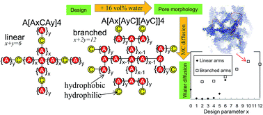
Polymer aggregation at a water content of 16% by volume is modelled by dissipative particle dynamics. The polymers contain a central hydrophobic bead from which four identical arms sprout out. For type L architectures each arm contains six hydrophobic A and one hydrophilic C bead whose position is varied ([A6−yCAy], 0 ≤ y ≤ 6). Each arm for type B architectures is two times larger and contains two branches with end grafted hydrophilic beads (A12−2y[AyC][AyC], 0 ≤ y < 6). Type L architectures reveal the narrowest pores when the C beads are located near the middle of each arm, while for type B they decrease with y. Also six architectures with pairwise unequal linear arms are considered. Among all 19 architectures the best connected hydrophilic clusters, derived from Monte Carlo tracer calculations through the pore networks, are obtained for type B architecture which contain short [AC] branches. The results are explained by calculating for each architecture the average number of A–A and A–C bonds that A beads are separated from the nearest C bead in each architecture. These insights might guide pore network design strategies in order to develop alternative polymer electrolyte membranes with low percolation thresholds for proton diffusion.
Molecular dynamics (MD) has been frequently used to study phase separation and water and/or proton transport through Nafion.10–23 But system sizes are mostly limited, while actually these should be much larger than the characteristic distance of ∼5 nm (corresponding to the Bragg spacing) in order to gather essential information about pore connectivity. Large scale atomistic simulation with millions of atoms still requires special assumptions such as pre-assumed starting morphologies23 or a repetitive system size increase by including periodic images that are subjected to equilibration.12 Therefore, to model the Nafion morphology for a system size up to O (104 nm3) various methods have been applied, such as Coarse Grained MD (CGMD),24,25 bond fluctuation model,26 Monte Carlo in combination with the Reference Interaction Site Model (MC/RISM),27 self-consistent approaches28,29 that are based on mesoscale dynamic density functional theory and Dissipative Particle Dynamics (DPD).30–37
In the DPD study on Nafion by Yamamoto and Hyodo30 the pore structure at various hydration levels was calculated for a system size of ∼2.3 × 10⁴ nm3 for a Nafion1200 membrane (1200 is the equivalent weight (EW) of 1200 g polymer per one mole of sulfonic sites). With increasing water content the water clusters were observed in ref. 30 to increase in size and become more distant from each other. The resulting increase in Bragg spacing with water uptake is in agreement with experiment.9
A later DPD study31 aimed to simulate the change in pore connection and long range water transport when the EW of Nafion is varied. For this purpose Dorenbos and Suga31 mapped the hydrophilic pore networks onto a cubic grid, and mimicked water diffusion by Monte Carlo (MC) simulation. From the confined (Brownian) movement of thousands of tracer particles through the hydrophilic phase (containing both water and acidic side chain groups) long range transport was studied. Diffusion constants obtained from this hybrid “DPD-MC” study matched well experimental values as a function of hydration level when the water mobility within the pores was assumed to resemble that of pure water.31 Interestingly also quasi elastic neutron scattering (QENS) experiments38,39 on Nafion revealed that at a hydration level of λ = 5 water molecules per SO3H site, the local water mobility is close to that of pure water. Later DPD-MC studies32 revealed that for a statistical distribution of side chains water diffusion increases when compared with uniformly distributed side chains. The approach to study pore connectivity and solvent diffusion by hybrid DPD-Monte Carlo (DPD-MC) calculations was also adapted recently by Vishnyakov and Neimark.37
DPD-MC studies on ∼100 amphiphilic polymer architectures have been published already.40–49 These (grafted or block type) polymers contain hydrophobic (A) and hydrophilic (C) molecular fragments that are coarse grained into beads. By systematically varying e.g. the side chain length,40,41,46 side chain distribution,43,44,46 side chain architecture,44,45,49 ion exchange capacity (IEC),40–43 molecular weight (MW),44 or hydrophilic position within the block polymers,40,42 various trends on how pore morphology, solvent diffusion, and percolation thresholds depend on architecture were predicted. The architectures had in common that a majority of beads are hydrophobic, with hydrophilic C bead fraction within the architectures mostly ranging between 5−1 and 9−1. The main trends obtained from these works were summarized recently in ref. 47–49.
An important finding was that, when the water volume fraction is kept the same, the distance between pores depends linearly on a parameter that can be directly obtained from the architectures’ (DPD) formula.47–49 This parameter, 〈Nbond〉, is the average of the number of bonds that each hydrophobic A bead within the architecture is separated from the nearest C bead.47–49 Independent of IEC, an increase in 〈Nbond〉 was predicted to result in larger pores (and Bragg spacing) that are mostly better connected, resulting in increased diffusion. When comparing architectures of the same IEC then, water diffusion (at fixed water contents) generally increases with 〈Nbond〉. As a result lower percolation thresholds for diffusion are obtained when 〈Nbond〉 increases for model membranes of the same IEC.47–49 This suggests that for various architecture types, it is possible to predict how pore size and diffusion depend on polymer architecture (DPD formula) by just evaluating the value of 〈Nbond〉. This is verified here by modeling the aggregation of amphiphilic star polymers within a solvent (water) and by analyzing both the morphology and the diffusion of water through the hydrophilic pore networks. Star polymers with linear or branched arms are considered. These types of polymers were not yet studied using the DPD-MC method.
Phase separated morphologies are calculated by DPD for amphiphilic star polymers at a water content of 16% by volume (ϕw = 0.16). Each polymer contains a majority of hydrophobic A beads and a minority of hydrophilic C beads. Rather than calculating χ parameters between molecular fragments by atomistic simulation, the χ parameters are given a priori. Thirteen star polymers along with their DPD parameterizations are defined in the Computational details. In the Results and analysis the pore morphologies are analyzed and pore connectivity is estimated by MC tracer particle trajectory calculations. The obtained trends are explained in the Discussion by evaluating the parameter 〈Nbond〉. Also additional calculations are presented for six star polymers that contain two types of arms that differ in length or hydrophilic C site distribution within the arms.
![]() | ||
Fig. 1 DPD representations of the star polymer architectures. The adapted values for x and y are listed in Table 1. |
Linear arms: A[AxCAy]4 | x | y | x + y | |C| | 〈Nbond〉 | dCl–Cl (nm) | DMC(W) | DMC(W + C) | ϕp |
---|---|---|---|---|---|---|---|---|---|
L1: A[CA6]4 | 0 | 6 | 6 | 4/29 | 3.4 | 4.79 | 0.051 | 0.150 | 0.13 |
L2: A[ACA5]4 | 1 | 5 | 6 | 4/29 | 2.64 | 4.42 | 0.0041 | 0.068 | 0.18 |
L3: A[A2CA4]4 | 2 | 4 | 6 | 4/29 | 2.2 | 3.61 | 0.0018 | 0.046 | 0.23 |
L4: A[A3CA3]4 | 3 | 3 | 6 | 4/29 | 2.08 | 3.82 | 0.0032 | 0.063 | 0.25 |
L5: A[A4CA2]4 | 4 | 2 | 6 | 4/29 | 2.28 | 4.09 | 0.0067 | 0.084 | 0.22 |
L6: A[A5CA1]4 | 5 | 1 | 6 | 4/29 | 2.8 | 4.39 | 0.0291 | 0.140 | 0.17 |
L7: A[A6C]4 | 6 | 0 | 6 | 4/29 | 3.64 | 4.99 | 0.1013 | 0.209 | 0.12 |
Branched arms: A[Ax[AyC][AyC]]4 | x | y | x + 2y | |C| | 〈Nbond〉 | dCl–Cl (nm) | DMC(W) | DMC(W + C) | ϕp |
---|---|---|---|---|---|---|---|---|---|
B1: A[A2[A5C][A5C]]4 | 2 | 5 | 12 | 8/57 | 3.67 | 5.05 | 0.092 | 0.202 | 0.12 |
B2: A[A4[A4C][A4C]]4 | 4 | 4 | 12 | 8/57 | 3.94 | 5.03 | 0.095 | 0.206 | 0.11 |
B3: A[A6[A3C][A3C]]4 | 6 | 3 | 12 | 8/57 | 4.37 | 5.28 | 0.117 | 0.235 | 0.10 |
B4: A[A8[A2C][A2C]]4 | 8 | 2 | 12 | 8/57 | 4.96 | 5.86 | 0.158 | 0.330 | 0.09 |
B5: A[A10[AC][AC]]4 | 10 | 1 | 12 | 8/57 | 5.71 | 6.40 | 0.198 | 0.397 | 0.07 |
B6: A[A12[C][C]]4 | 12 | 0 | 12 | 8/57 | 6.63 | 6.70 | 0.184 | 0.380 | 0.06 |
Water is represented by W beads. A conversion to physical units is achieved by assuming that the volume V that each bead represents is equal to the volume occupied by 4 water molecules. This is the same as in previous works30,31,42–49 i.e. Nm = 4 and V = 0.12 nm3. This volume reproduces the mass density of 1 g cm−3 for liquid water. The volumes of the A and C beads are also 0.12 nm3, therefore acidic site densities are 1.92 and 1.95 mmol cm−3 for the linear and branched architectures, respectively. For a polymer with mass density of 1 g cm−3, the ion exchange capacity (IEC) is then ∼520 g mol−1.
![]() | (1) |
The sum in eqn (1) is over all particles j located within the cutoff distance rc. The conservative force decreases with distance:
![]() | (2a) |
rij = ri − rj, rij = |rij|, ![]() | (2b) |
FRij = σωR(rij)ζij(Δt)−0.5(kBT)−1![]() | (3) |
FDij = −γωD(rij)(![]() ![]() | (4) |
![]() | (5) |
Noise (σ) and friction (γ) are related by σ2 = 2γkBT,59 with σ = 3, γ = 4.5, kB the Boltzmann constant and T the temperature. All three forces act along the line of centers and conserve linear and angular momentum. Adjacent polymer beads are joined by a spring force with spring constant C = 50 and equilibrium bond distance R0 = 0.85rc:
FSij = −C(rij − R0)![]() | (6) |
Bead masses and unit of time τ = rc (m/kBT)0.5 are scaled to 1. kBT is kept at 1.0 by using a modified Verlet integration scheme58 with empirical factor 0.65 and time step Δt = 0.05τ. The bead density ρ is 3.
Repulsions between similar beads are set at 104. This reproduces the water compressibility when the simulation box only contains W beads.30,32 Micro phase separation is caused by the larger repulsions between incompatible A–W and A–C beads by setting aAW and aAC at 124.4. According to eqn (7) these repulsions correspond with a χ value of 4.9.42 These χ values are comparable to those calculated between incompatible molecular fragments in the DPD parameterization of Nafion by Yamamoto and Hyodo.30 The χ parameter between C and W beads is set at −2.6, which is close to the value of −2.79 calculated in ref. 30 between water and CF2CF2SO3H. The repulsion between C and W beads is equal to aCW = 93.2.
Δaij = (4.16 ± 0.15) × χij | (7) |
In order to predict trends, atomistic calculations for predefined chemical fragments to obtain χ parameters is omitted and the experimental difficulties to synthesize the star polymers are not addressed. A and C beads might contain ether linkages, hydrocarbon, (fluoro)aromatic or (hydro)fluorocarbon fragments, etc. A and W (or C) beads are mutually incompatible. For instance the molecular (A) fragments –O–CF2–CF(CF3)–O–, –O–CF2–CH2–CF2 are hydrophobic. The χ parameter between –O–CF2–CF(CF3)–O– and four H2O molecules, is ∼4.9 (ref. 30) which is similar to the χ value between A and W beads in this work. Also χ parameters determined in DPD studies by Wu et al.35,36 on perfluorosulfonic acid (PFSA) membranes compare with those adapted here: those between the polymer hydrophobic (backbone) and hydrophilic beads (CF3SO3H·3H2O complex) were 6.86 and 7.07 in ref. 35 and 36, respectively. Since Wu et al.35,36 assumed bead volumes of 0.18 nm3, these χ parameters correspond to ∼4.7 when bead fragments would be (hypothetically) chosen to be 0.12 nm3 in size.48
The water volume fraction ϕw is obtained from the number NA, NW and NC of A, W and C beads by eqn (8).
![]() | (8) |
The water content in each simulation is the same with ϕw = 0.16. The phenomenon of membrane swelling (gradual increase of water content) is not modelled here. Instead this work only considers equilibrium-like morphologies at fixed hydration.
The system is cubic with edge length L = 24rc, and contains ρL3 = 3 × 243 = 41472 beads. Since V = 0.12 nm3, the box volume (ρL3V) is 5.0 × 10³ nm3. Since this volume is equal to (24rc),3 one DPD length unit corresponds with a physical length scale of rc = ρV1/3 = (3 × 0.12 nm3)1/3 or 0.71 nm. Box edges are L × rc ∼ 17 nm (L = 24). The simulation box contains 1201 linear or 611 branched star polymers. Periodic boundary conditions are applied in each orthogonal direction. Morphologies are stored at time intervals of 2000Δt up to 4 × 10⁴Δt resulting in a total of 380 morphologies.
![]() | ||
Fig. 2 Pore networks calculated for star polymers with (a) linear arms (L1 to L7) and (b) branched arms (B1 to B6). C beads are yellow (light grey) and W beads are blue (dark). Visualization was performed using the VMD-visual molecular dynamics package.60 |
The inter cluster distance, dCl–Cl, is derived from the pair correlation function of the water beads, g(r). The g(r) obtained for the morphologies in Fig. 2(a) and (b) are displayed in Fig. 3(a) and (b), respectively. The pair correlation function calculated for a system composed of only W beads is also included in Fig. 3(a). For pure water maxima appear at ∼0.6 nm, ∼1.0 nm and ∼1.5 nm. The maxima near 0.6 nm, 1.0 nm are also observed for the star polymers, while a shoulder still occurs near 1.5 nm. For the star polymers the position of the maxima in g(r), located between ∼3 nm and ∼8 nm, correspond to the average separation between clusters,30 or dCl–Cl.31
![]() | ||
Fig. 3 W bead pair correlation functions for architectures with (a) linear arms and (b) branched arms. DPD time t = 4 × 10⁴Δt. In (a) the pair correlation function for pure water is included. |
Fig. 3(a) reveals that for the linear star polymers (L1 to L7) dCl–Cl initially decreases and then passes through a minimum for L3 and L4, and increases again (L5, L6 and L7). For the branched star polymers (B1 to B7) the position of the maximum gradually increases with increase of x (or decrease of the length y + 1 of the branches) (Fig. 3(b)).
In Fig. 4(a) and (b) the dependence of dCl–Cl on DPD time are plotted. After an initial increase dCl–Cl stabilizes. dCl–Cl averages obtained over the sampling period 3.0 × 10⁴Δt to 4.0 × 10⁴Δt are listed in Table 1. In Fig. 4(c) the averages are plotted against architecture label number. For the linear star polymers dCl–Cl is largest for L1 (A[CA6]4) and L7 (A[A6C]4), and smallest for L3 (A[A2CA4]4). For the branched star polymers the largest dCl–Cl occurs for the B6 architecture A[A12[C][C]]4.
At MC time t′ = 0 two thousand tracer particles (Ntracer = 2000) are put at randomly selected nodes that belong to the pore phase. At each Monte Carlo step (MCS) a jump trial towards a neighboring node in the +x, −x, +y, −y, +z, or −z direction, is randomly selected for each particle. A jump occurs when this site belongs to the pore phase. Diffusion constants, D, are obtained from the mean square displacement (MSD) of Ntracer trajectories (eqn (9a)). By plotting MSD against MC time, D is derived from the slope d(MSD)/dt′ (eqn (9b)).
![]() | (9a) |
![]() | (9b) |
i(t’) is the position of particle i at time t′. The slopes will eventually converge to the value 6D (eqn (9b)). MSD curves calculated for diffusion through the W pore networks generated at t = 4 × 10⁴Δt are shown in Fig. 5(a) (linear star polymers) and Fig. 5(b) (branched star polymers). In these figures the case that represents pure water, for which every jump trial is accepted, is included. The MSD is expressed in units of (inter node distance)2 and time in MCS. The slope, d(MSD)/dt′, for pure water is equal to one (internode distance)2/MCS. The diffusion constant, DMC, within the membrane relative to that of pure water is thus given by the slopes. The slopes (Δ(MSD)/Δ(MCS)) are determined by linear regression over the time interval 1 × 10⁶ to 2 × 10⁶ MCS. DMC is calculated from eqn (10).
![]() | (10) |
Fig. 5(a) reveals that for the linear star polymers diffusion through the W pore networks is highest for architecture L7 for which the C bead is located at the end of each arm. Also for L1, for which the C beads in each arm are located near the central A bead, water diffusion is much higher than for architectures L3, L4 and L5 with C beads located nearer the center of the arms. From Fig. 5(b) it is clear that for branched star polymers overall diffusion through the W pore networks increases with decreasing length (y + 1) of the branches. Water diffusion is most pronounced for the architectures B5 (A[A10[AC][AC]]4) and B6 (A[A12[C][C]]4) for which y = 1 and 0, respectively.
In Fig. 5(c) and (d) the MSD curves obtained for diffusion through the W + C networks are displayed. Diffusion through the W + C networks is always faster than through the W networks, but for both types of pore definitions the same trends are obtained.
The reason for the observed dependency of dCl–Cl on architecture is most easily explained by recognizing that a large inter cluster distance, dCl–Cl, implicitly requires large hydrophobic A regions. The system strives to maximize the number of hydrophilic–hydrophilic and hydrophobic–hydrophobic interactions and to minimize hydrophilic–hydrophobic interactions. When the bonds between polymeric beads are cut this will result in a mixture of C and W beads fully phase separated from a majority A phase.42 But since the A and C beads within the polymers are bonded to each other, morphologies that contain large pores with minimal interface area require that the C beads are expelled from the hydrophobic A region. This is achieved if the C beads arrange along the pore walls.
Hydrophobic regions can only be large when a significant fraction of A beads is, in terms of the number of A–A and A–C bonds, distant from a nearest C bead. Therefore large hydrophobic A regions and high dCl–Cl values can occur only for architectures for which the average number of A–A and A–C bonds, 〈Nbond〉, towards a nearest C bead is large. This means that for two architectures the one for which 〈Nbond〉 is largest is expected to reveal a larger dCl–Cl value and larger pores. When the number of bonds between A beads towards the nearest C bead are averaged, then 〈Nbond〉 turns out to depend quadratically on x according to eqn (11a) and (11b) for the linear and branched star polymers, respectively.
![]() | (11a) |
![]() | (11b) |
Eqn (11a) and (11b) can be readily derived from the DPD formula. For example, for (symmetric) linear star polymers composed of m equal arms, with each arm containing N A beads and one C bead, the DPD formula is A[AxCAN−x]m. The central A bead is always separated from the nearest C bead by a distance of x + 1 bond length(s). For each of the N A beads within an arm the nearest C bead is always located within that same arm. These distances are summed up according to eqn (11c). When adding the contributions from the m arms and the central A bead, then the general eqn (11d) is obtained. For architectures L1 to L7, the number of arms m = 4 and N = 6, when these are substituted in eqn (11d) and divided by the total number of A beads (=25) then eqn (11a) is retrieved. Eqn (11b) can be derived in a similar way for the branched star polymers.
![]() | (11c) |
![]() | (11d) |
The values of 〈Nbond〉 according to eqn (11a) (L1 to L7) and eqn (11b) (B1 to B7) are listed in Table 1. When plotting dCl–Cl against 〈Nbond〉, a linear increase is obtained (Fig. 6(a)). Also DMC(W) and DMC(W + C) tend to increase with 〈Nbond〉, as shown in Fig. 6(b).
![]() | ||
Fig. 6 (a) dCl–Cl and (b) DMC(W) and DMC(W + C) as a function of average number of bonds between A beads and nearest C bead. |
For the present star polymers it is concluded that generally an increase in dCl–Cl, due to increase in 〈Nbond〉, results in larger and better connected clusters that favor water transport. This is in line with the observed dependency on 〈Nbond〉 for various other architectures.47–49 Among the 13 star polymers in Table 1 the largest pores and highest diffusion constants are obtained for architectures B5 and B6 with short [AC] and [C] branches, respectively.
In fuel cell PEMs the hydrophilic pores serve as ion channels for proton transport. Therefore proton conductivity depends strongly on chain architecture. For fuel cell applications it is imperative for PEMs to have good connections between hydrophilic clusters, especially at low hydration values. Percolation thresholds, ϕp, were estimated in previous DPD-MC studies for 34 grafted polymeric architectures with linear41,43,48 and 4 with Y-shaped49 side chains with the C bead fraction (|C|) ranging between 10−1 and 5−1. ϕp was found to decrease with 〈Nbond〉 for architectures with the same C bead fraction, while for architectures with the same 〈Nbond〉 percolation thresholds decrease with increase of C bead fraction (or IEC). These two phenomena are captured into a fitting equation given by eqn (12).47,49 Actually, for the in total 38 architectures the calculated ϕp are on average within 3.4% to those calculated by eqn (12).
ϕp = 0.39/[〈Nbond〉 + 4 − (1.612 × |C|)−1] | (12) |
For the star polymers in Table 1 the C bead fraction is |C| = 7.25−1 (L1 to L7) or 7.125−1 (B1 to B6). Assuming eqn (12) is also valid for these architectures and substituting the corresponding |C| and the 〈Nbond〉 values into eqn (12), then the ϕp values listed in Table 1 are obtained. The percolation thresholds in ref. 41, 43 and 48 were defined as the water volume fraction at which DMC(W) = 0.01. In this work DMC(W) was calculated for ϕw = 0.16. Interestingly, for the architectures (L2, L3, L4, and L5) with DMC(W) < 0.01 the percolation thresholds based on eqn (12), are indeed expected to be larger than ϕp = 0.16 (Table 1). Among the linear star polymers L1 and L7 are expected to reveal the lowest percolation thresholds, while among the branched architectures the lowest percolation thresholds are expected for A[A10[AC][AC]4 (B5) and A[A12[C][C]4 (B6). This is consistent with the DMC(W) values in Table 1 for which also for the linear L1 and L7, and branched B5 and B6 architectures the highest diffusion constant at ϕw = 0.16 is obtained. It should be emphasized that in this work no percolation thresholds were determined, and percolation thresholds in Table 1 should be considered as an educated guess reflecting expected trends of the ϕp dependence on architecture.
The architectures in Table 1 (Fig. 1) were symmetric. For the seven linear star polymers (L1 to L7) the length of each arm and C bead location was the same. Among the six branched polymers (B1 to B6) each of the four arms was equal. For the thirteen architectures dCl–Cl and overall DMC(W) increase linearly with 〈Nbond〉 (Fig. 6(a and b)). It is expected that they also depend on 〈Nbond〉 for model star polymers that contain two or more different arms. For example, one can imagine (linear) star polymers (C1, C2, C3, and C4 in Fig. 7) with four arms of equal length, each arm contains one hydrophilic C bead, two of them are placed at the end of the arms while the other two C beads are placed at a predefined position within the other two arms. The corresponding DPD formula is then A[A6C]2[AxCAy]2, with x + y = 6. For x = 0, 1, 4 and 5 the 〈Nbond〉 values are then 2.92, 2.72, 2.68, and 3.2, which is lower than the value of 3.64 for the L7 architecture (A[A6C]4). For these architectures (C1 to C4) the dCl–Cl values are then expected to be lower than for L7 in Table 1 (5.0 nm).
On the other hand, for architectures with a bimodal arm length distribution, A[AxC]2[A12−xC]2 with 0 ≤ x < 6, 〈Nbond〉 increases linearly with decrease in x. For x = 1 (A[AC]2[A11C]2) and x = 0 (A[C]2[A12C]2) 〈Nbond〉 = 3.84 and 3.88 respectively, larger than 〈Nbond〉 = 3.64 for L7 architecture. For these two architectures, displayed as C5 and C6 in Fig. 7, slightly larger dCl–Cl are expected than for L7.
The above predictions were verified by performing six additional calculations for the architectures in Fig. 7. The results are listed in Table 2. For C1 (A[A6C]2[CA6]2), C2 (A[A6C]2[ACA5]2), C3 (A[A6C]2[A4CA2]2) and C4 (A[A6C]2[A5CA]2) dCl–Cl is indeed lower than 5 nm. For architectures C5 (A[AC]2[A11C]2) and C6 (A[C]2[A12C]2), dCl–Cl is indeed slightly larger than the value of 5.0 nm obtained for L7. Actually, dCl–Cl values for these six architectures are on average within 3% of the fitting equation given in Fig. 6(a).
Architecture | 〈Nbond〉 | dCl–Cl (nm) | DMC(W) | DMC(W + C) |
---|---|---|---|---|
C1: A[A6C]2[CA6]2 | 2.92 | 4.56 | 0.0037 | 0.027 |
C2: A[A6C]2[ACA5]2 | 2.72 | 4.39 | 0.0059 | 0.032 |
C3: A[A6C]2[A4CA2]2 | 2.68 | 4.54 | 0.022 | 0.087 |
C4: A[A6C]2[A5CA]2 | 3.2 | 4.78 | 0.046 | 0.138 |
C5: A[AC]2[A11C]2 | 3.84 | 5.08 | 0.097 | 0.217 |
C6: A[C]2[A12C]2 | 3.88 | 5.14 | 0.072 | 0.147 |
L7: A[A6C]4 | 3.64 | 4.99 | 0.101 | 0.209 |
DMC(W) and DMC(W + C) values are also listed in Table 2. Overall these increase with 〈Nbond〉. An exception is the C6 architecture A[C]2[A12C]2 which has two pendent C beads bonded to the central A bead. Architecture B6 (A[[A12[C][C]]4) (Table 1) shares this property and also deviates significantly from the solid trend line in Fig. 6(b). This is in line with previous results for architectures with this property. Namely, for A11[C][C]-6 (Fig. 13(b) and 15(b) in ref. 48) and A3[A8[C][C]-6 (Fig. 15(b) in ref. 48) also DMC(W) values significantly deviate from the trend lines obtained for ∼60 architectures when DMC(W) is plotted against 〈Nbond〉|C||A|−1 (|C| and |A| are the C and A bead fraction within the architecture).
When plotting in Fig. 8 DMC(W) from Tables 1 and 2 against 〈Nbond〉|C||A|−1, then most of these data (open squares and filled diamonds) follow the trend given by the solid line. Exceptions occur for C1, L1, C6 and B6, whose corresponding data points are located along the dashed line. The DMC(W) values for the grafted polymers A3[A8[C][C]]-6 and A11[C][C]-6 taken from ref. 45 and 48 also fall below the solid line and are located near the dashed line.
![]() | ||
Fig. 8 DMC(W) as function of 〈Nbond〉|C||A|−1 (=〈Nbond〉|C||1 − C|−1) for the architectures listed in Tables 1 and 2. Results for A3[A8[C][C]]-6,45 A11[C][C]-6,48 A3[A8C2]-6,45 A8[A2C2]-3,44 A8[A2C2]-6 (ref. 44) and A10C2-3 (ref. 46) are included. Water content ϕw = 0.16. Inset: dCl–Cl vs. 〈Nbond〉. |
Apparently these exceptions are due to the lack of flexibility for the two C beads that are bonded to the same A bead to connect properly the water pores in order to facilitate water diffusion: C beads for these architectures are only 2 (A–C) bond distances separated from each other. Indeed, when C beads are separated by only one (C–C) bond, such as for the grafted architectures A3[A8C2]-6,45 A8[A2C2]-3,44 A8[A2C2]-644 and the block polymer A10C2-3 taken from ref. 46 (hatched crosses in Fig. 8) diffusion decreases further. Interestingly, also for these four data points DMC(W) increase linearly with 〈Nbond〉|C||A|−1 as indicated by the dotted line in Fig. 8.
Each polymer was assumed to be very flexible since no bending constraints were imposed on the arms. Therefore phase separation was only governed by the water content, specific polymer architecture, and the DPD repulsions between beads that scale linearly with the assumed χ parameters (eqn (7)). Care should be taken when the current trends regarding pore morphology and diffusion are compared with those obtained from real membranes. For real polymers bending rigidity depends on the molecular fragment that each bead represents. In this work the actual chemical species represented by each bead was not specified.
The database that has now been collected for a fixed set of χ parameters (this work and ref. 32 and 40–49) contains architectures that lack any bending rigidity. This lack might be sufficient for obtaining the overall linear increase of dCl–Cl with 〈Nbond〉 as observed in Fig. 8 and in e.g. ref. 47 (Fig. 12(a)) and in ref. 48 (Fig. 14). It will be interesting to verify whether the trends in this work can be retained from large scale MD simulations on star polymers composed of flexible arms.
For PFSA-like architectures some evidence of the dependence of inter-cluster distance and diffusion on 〈Nbond〉 can be deduced from CGMD.25 Allahyarov et al.25 studied architectures composed of hydrophobic backbones for which at regular intervals hydrophobic side chains with pendent hydrophilic SO3− head groups are attached.
Side chain lengths and their separation along the backbones were systematically varied, resulting in EW ranging between 840 and 1840. When inter cluster distances, derived from the sulfur–sulfur pair correlation functions (Rss in Table 1 of ref. 25), are plotted against the average number of bonds between the hydrophobic united atoms and the nearest head groups, then a linear increase with 〈Nbond〉 can be retrieved. Allahyarov et al.25 did not present water diffusion coefficients, but for EW1840 membranes (D–F in ref. 25) proton diffusion does increase linearly with side chain length and 〈Nbond〉, in line with Fig. 8 and DPD-MC studies31,40,41 (e.g. Fig. 8 in ref. 41). For membranes (A–D in ref. 25) with equal side chain lengths an increase in EW, due to increased side chain spacing, resulted in reduced proton diffusion. This trend is indeed also deduced from DPD-MC studies40 (Fig. 14 in ref. 40, increase x along y = constant curves). Based on ∼30% decrease in the factor 〈Nbond〉|C||1 − C|−1 for EW1840 membrane D (∼0.32) compared to EW840 A (∼0.42) water diffusion is expected to be highest for membrane A at fixed ϕw. It is noted that in the simulations of ref. 25 ϕw is estimated between ∼0.053 (D–F) and ∼0.11 (A) which is lower than in this work. Therefore the water clusters in ref. 25 did mostly not form a continuous pathway and protons diffused via temporal bridges as also proposed for hydrated Nafion by Vishnyakov and Neimark.15
Simulation studies on Nafion31,33 predict that inter cluster distance and Bragg spacing (dBragg) increase linearly with EW (for 0.1 ≤ ϕw ≤ 0.4)33 and ϕw (at fixed EW) and dBragg depends on ϕw and EW according to eqn (13a).31 When dBragg is expressed vs. 〈Nbond〉 (from Table 3 in ref. 48) then for Nafion constructed of 5 (A′x[B′C′]) repeat units31,33 (nominal EW = 400 + 200x) eqn (13b) is obtained. For fixed ϕw, dBragg then increases linearly with 〈Nbond〉. Realistic Nafion contains several hundreds of side chains and 〈Nbond〉 approaches the asymptotic value which for EW = 800 (A′2[B′C′]-inf), 1000, 1200 and 1400 (A′5[B′C′]-inf)31 is respectively 2, 2.25, 2.6 and 2.833, i.e. 〈Nbond〉 ∼ 0.896 + 0.001384 × EW. Gierke et al.6 measured that the fractional volume gains ϕv at full hydration decreases gradually with EW from 0.87 (EW = 944) to 0.133 (EW = 1790) which corresponds to ϕw = ϕv(ϕv + 1)−1 ranging from 0.47 to 0.12. Fig. 9 displays the experimental (from Table 1 in ref. 6) and calculated (from eqn (13b)) Bragg spacing against 〈Nbond〉. The agreement between experiment and calculation confirm that at least for PFSA membranes the characteristic distances (dBragg; dCl–Cl) increase with 〈Nbond〉 for various ϕw.
dBragg = 2.66 nm + 0.0109 × (EW − 450)′ × ϕw | (13a) |
dBragg (nm) = 6.6275 × ϕw × 〈Nbond〉 + 2.66 − 9.395 × ϕw | (13b) |
![]() | ||
Fig. 9 Experimental (filled symbols) and calculated Bragg spacing according to eqn (13b) (open symbols) at full hydration for Nafion membranes of EW = 944–1790 EW plotted against 〈Nbond〉. The slopes are obtained according to eqn (13b) for the indicated ϕw. |
In DPD-MC studies31,32,40–49 water diffusion within the nm pores was assumed to equal that of pure water. For high IEC membranes the acidic site density might drastically affect the local diffusion since more water is near the hydrophilic sites where polarization effects can reduce mobility. Indeed for ϕw = 0.08 to ∼0.2 experimental water diffusion constants for the short side chain Dow858 membrane are significantly smaller than for Dow1084 (see Fig. 4(a) in ref. 9), which cannot be explained by differences in the factor 〈Nbond〉|C||1 − C|−1. But when comparing water diffusion within PFSA membranes of equal IEC then indeed water diffusion increases with 〈Nbond〉: for Nafion1100 at ϕw = 0.08 to ∼0.16 diffusion is about twice that of Dow1084 (Fig. 4(a) in ref. 9). This agrees with the prediction that for Dow1000 membranes diffusion is lower than for Nafion1000 membranes31 and that at fixed |C| diffusion increases with 〈Nbond〉.
For the star polymers overall DMC(W) increases with 〈Nbond〉|C||1 − C|−1 (Fig. 8). Notable exceptions occur for architectures in which C beads are connected to each other or for which A beads are bonded to more than one C bead. For these cases an increase in pore size does not result in increased diffusion. This is possibly caused by a narrowing of bottlenecks for diffusion but is not further investigated in this work.
Generally for fixed IEC (i.e. constant |C||1 − C|−1) DMC(W) can be increased by placing C beads in such a way that on average hydrophobic beads are more distant from the nearest C bead. From the database established thus far40–49 those architectures with high 〈Nbond〉 and high IEC the largest reveal the largest DMC(W) at ϕw = 0.16. These are the grafted A3[A6[AC][AC]-6 (ref. 45 and 49) (〈Nbond〉 = 5.05) and A3[A8[C][C]-6 (ref. 49) (〈Nbond〉 = 5.92) for which DMC(W) = 0.19.45 These compete well with the star polymers B5 (A[A10[AC][AC]]4) (DMC(W) = 0.2) and B6 (A[A12[C][C]]4) (DMC(W) = 0.18) with 〈Nbond〉 being respectively 5.71 and 6.63.
Most DPD-MC studies41–43,45–49 dealt with grafted architectures since for a fixed IEC (constant |C|) these allow for designs with large 〈Nbond〉 values, such as those containing Y-shaped side chains. For amphiphilic block type architectures large 〈Nbond〉 can only be obtained when hydrophilic fragments are grouped together,40 or non-uniformly distributed within the backbones.42 In order to be competitive (with respect to water diffusion or proton conductivity) amphiphilic block copolymers with large and well connected pores can be accomplished by grouping hydrophilic fragments together40,61 or by placing them non-uniformly along the backbone.42 For instance Komarov et al.61 modelled the self-organization of AnB24−n block copolymers with n consecutively connected hydrophilic (sulfonated) A and 24 − n hydrophobic non-sulfonated B blocks at ϕw = 0.3. With increased sulfonation degree the body centred cubic, hexagonally packed cylinder, lamellar, gyroid, hexa-perforated and lamellar structures were obtained. The gyroid phase was observed by Park et al.62 who synthesized polystyrenesulfonate-block-polymethylbutylene (PSS-b-PMB) copolymers. The PSS blocks contain partially sulfonated styrene rings and PMB blocks are hydrophobic. Within the PSS phase sulfonated styrene form hydrophilic domains that, when hydrated, associate with water.
To avoid CO poisoning of catalyst material PEM fuel cells should ideally operate at elevated temperatures. But at high temperature and low relative humidity (RH) pores might dry out reducing proton conductivity. Interestingly, Park et al.62 found that within PSS-PMT membranes pores with size less than 6 nm are capable of retaining water at 96 °C (RH = 50%), resulting in high proton conductivities, while membranes with larger pores dried out, possibly caused by capillary condensation.62 Since large pores might dry out it may be wise to design architectures that maximize the factor 〈Nbond〉|C||1 − C|−1 for restricted values of 〈Nbond〉. In this way pore sizes can be kept small enough to retain water at elevated temperatures and low RH.
Water diffusion and inter cluster distance depend strongly on architecture. For the star polymers with linear arms the inter cluster distances (dCl–Cl) pass through a minimum for the architectures (L3, L4) with C beads located near the centre of each arm. For the polymers with branched arms dCl–Cl increases when the length of the 2 branches is decreased. This is explained by “bond counting”: the inter cluster distances, and therefore the pore size increase linearly with the value of 〈Nbond〉, which is the average number of bonds between a hydrophobic A bead and the nearest hydrophilic C bead. Water diffusion constants also tend to increase with the value of 〈Nbond〉. The most notable exception occurs for A3[A12[C][C]]-4 (B6) architecture with two C beads attached to an A bead.
The results are complemented with additional calculations for 6 alternative (model) star polymers with different arm lengths within a single architecture, or with similar arm lengths but with different C bead distributions within each arm. Among all 19 star polymers in this work the architecture with highest water diffusion constants is obtained for the branched architecture (B5) with short [AC] branches. These insights and the persistent trends observed in this and in previous work on model polymer architectures might guide pore network design to obtain low percolation thresholds for proton diffusion in PEMs.
This journal is © The Royal Society of Chemistry 2016 |