Synthesis and electrochemical study of sodium ion transport polymer gel electrolytes

Yuan Xue and David J. Quesnel*
Materials Science Program, Mechanical Engineering Department, University of Rochester, Rochester 14627, USA. E-mail: david.quesnel@Rochester.edu; Fax: +1 585 256 2509; Tel: +1 585 275 5215

Received 12th November 2015 , Accepted 8th January 2016

First published on 14th January 2016


Abstract

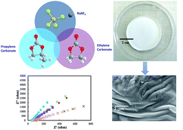
This research demonstrates a new, high conductivity sodium ion polymer gel electrolyte (PGE), which is prepared using a solution casting technique. The prepared PGE consists of a plasticized polymer blend of poly(methyl methacrylate) (PMMA) and polycarbonate that serves as a framework to immobilize phase separated interconnected liquid rich regions of ethylene carbonate (EC) and propylene carbonate (PC). Portions of these liquids that remain dissolved in the polymer blend act as plasticizers while interconnected liquid regions provide an all-liquid conductive pathway. A loosely bonded sodium salt, sodium tetrafluoroborate (NaBF4), was added to the PGE to decrease the crystallinity of the polymer blend, thus lowering energy barriers for ion transfer in the blend and providing more charge carriers in the liquid rich phases to enhance the overall ionic conductivity of the PGE. Peak ionic conductivity of 5.67 × 10⁻⁴ S cm−1 was observed from electrochemical impedance spectroscopy measurements of a PGE with 25 wt% NaBF4 which is more than two orders of magnitude larger than the same PGE without NaBF4 that demonstrates a conductivity of 1.03 × 10⁻⁶ S cm−1. The temperature dependence of ionic conductivity agrees with the Arrhenius equation from 20 °C to 90 °C. The activation energies for PGEs with different concentrations of NaBF4: 5 wt%, 15 wt% and 25 wt% are found to be 0.13, 0.17 and 0.28 eV respectively. Cyclic voltammetry confirmed that the PGEs are electrochemically stable over a wide potential range of −5 V to +5 V. In addition, transference number measurements, whose values varied from 0.83 to 0.93, demonstrate that these PGEs are ionic conductive electrolytes. The findings of this study are consistent with the development of a sodium ion conductive electrolyte films that are promising for use in non-aqueous advanced energy storage applications.

1. Introduction

The development of advanced energy storage systems is important for the adoption of renewable energy sources that will reduce the dependence on fossil fuels.1 Owing to their exceptionally high-energy density, secondary battery technologies, such as metal–ion batteries and metal–air batteries, are very promising candidates for fulfilling this role. In secondary battery development, special attention should be paid to the electrolyte since the properties of the electrolyte are key factors for batteries' efficiency, cost, environmentally friendly operation, and safety.2–4 Electrolytes previously evaluated are categorized as aqueous electrolytes, non-aqueous liquid electrolytes, and solid electrolytes. Despite advances in the development of sodium conducting electrolytes, long term use has shown that problems can occur. For example, aqueous electrolyte will react catastrophically with active anode metals leading to corrosion of less active anode metals.5–8 When oxygen radicals attack organic liquid electrolytes, the reactions have the tendency to form solid products and other dissolved compounds such as CO2.9–11 Solid undissolved products clog the cathode surface and reduce the lifetime of the battery. Thin solid ceramic electrolytes can provide a wide electrochemical window for batteries and are relatively stable compared to organic liquid electrolytes; yet the complicated manufacturing process, high-cost of fabrication, and poor mechanical properties of ceramics pose formidable challenges that could lead to catastrophic failures.12

A large effort has been invested to develop high-performance and cost-effective electrolytes for rechargeable energy storage devices. Polymer electrolytes have emerged as promising candidates. In the last decade, polymer electrolyte research has focused on poly(ethylene oxide) known as PEO.13,14 The ionic conductivity of PEO complexed with alkali metal salts as reported by Fenton in 197315 possessed ionic conductivity of 10−8 S cm−1 with life cycles from 200 to 300 in a lithium ion battery configuration. Sreekanth et al. studied sodium-ion conducting polymer electrolytes based on PEO complexed with different sodium nitrate (NaNO3) compositions,16 the highest ionic conductivity was determined to be 10−6 S cm−1 at room temperature with 30% NaNO3 added to PEO. Further study of solid-state polymer electrolytes uses alternative polymers with additives. Two such systems are: poly(vinyl pyrrolidone) + NaClO3 and poly(vinyl pyrrolidone) + poly(vinyl alcohol) + KIO3 which possess ionic conductivities of ∼10−7 S cm−1 and ∼10−6 S cm−1 at room temperature, respectively.17,18

Polymer gel electrolytes (PGEs) have been introduced in order to improve the ionic conductivity of polymer electrolytes and reduce the local segmental motion, which will prevent ion transportation.19–21 PGEs are formed by absorbing organic liquid electrolytes into a polymer framework which becomes plasticized, taking on the properties of a swollen polymer that is referred to as a gel. One can think of the polymer framework as a gelatinization agent that immobilizes the molecules of an otherwise liquid electrolyte which contains dissolved ionic species, holding them inside as they act to transport ions. PGEs are a flexible, free standing polymer frameworks with good chemical stability and comprise a polymer host and organic solvents, in which the organic solvents are immobilized by the polymer three dimensional network structures that can prevent liquid from escaping. Interaction between the solvents and the polymer framework provide the gel polymer high mobility within the network structure for ion transfer. The performance of PGEs can be enhanced by addition of metallic salts to the solvents at room temperature. The salts should have large anions and low dissociation energy so that they can be easily solvated by the polar solvents which are acting as the conducting medium. A gelled polymer electrolyte22 offers safer batteries with longer cycling life, little risk of leakage and easy fabrication into desired shapes and sizes.23 Ever since Iijima et al. found poly(methyl methacrylate) (PMMA) could be used as an effective gelatinization agent to immobilize organic liquids, PMMA based polymer gel electrolytes have been investigated with different plasticizers (organic liquids) and salt additives.24,25 PMMA is often chosen as the polymer host due to its side group of –COOCH3 which is compatible with a wide range of organic solvents, while affording a good ability to retain absorbed organic solvents. Organic solvents propylene carbonate (PC) and ethylene carbonate (EC), often used as liquid electrolytes, have been found to act as plasticizers for PMMA, softening the polymer framework and improving the mobility of the backbone. Their high dielectric constant increases the mobility of charged ions in the gelled system.26 However, PMMA is still too brittle to have practical application. Therefore, it may be appropriate to blend PMMA with chemically similar polycarbonate to provide a more mechanically robust polymer framework for the gel. Tang et al. developed such a polymer gel electrolytes as proton exchange membranes, through polymerization and ionic liquid imbibition technique, which has been demonstrated as a promising ion conductive electrolyte for fuel cell application.27,28

In the present study, we develop a polymer framework matrix by using a blend of PMMA and polycarbonate polymers obtained from low-cost commercially available sources. Trace additives used to control processing and machining of these materials will be overcome by the relatively large amounts of PC and EC organic liquids used to plasticize the matrix to the point it becomes a polymer gel electrolyte. Sodium tetrafluoroborate (NaBF4), a stable, cost-effective, and easily acquirable sodium salt, was chosen to add to the PGEs to enhance the ionic conductivity. Several experimental techniques such as scanning electron microscopy, electrochemical impedance spectroscopy, cyclic voltammetry, transference number measurements, and temperature dependent conductivity have been employed to characterize the PGEs. Results indicate a non-aqueous sodium ion conducting electrolyte that is suitable for application in sodium–ion batteries.

2. Experimental

2.1 Material preparation

The electrolyte membrane was prepared using solution casting techniques. Commercially available PMMA and polycarbonate (McMaster-Carr, Aurora, OH) were purchased as structural sheet materials (1.5 mm thick) and cut into small pieces, comparable with shredded material that might be obtained through recycling from manufacturing operations. The plastic pieces were mixed in a 1[thin space (1/6-em)]:[thin space (1/6-em)]1 weight ratio (2.00 grams of PMMA and 2.00 grams of polycarbonate) and dissolved in excess (50.0 ml) tetrahydrofuran (THF) (Alfa Aesar, Ward Hill, MA) solvent at 50 °C by stirring with a magnetic stirrer for several hours until the plastic had completely dissolved. Then, solid propylene carbonate (PC) (Alfa Aesar, Ward Hill, MA) and liquid ethylene carbonate (EC) (Alfa Aesar, Ward Hill, MA) were mixed in the ratio 1[thin space (1/6-em)]:[thin space (1/6-em)]2 (2.00 g PC and 4.00 g EC). Sodium tetrafluoroborate (NaBF4) (Alfa Aesar, Ward Hill, MA) was added to the PC/EC mixture, stirring at room temperature until fully dissolved. The amount of sodium tetrafluoroborate (NaBF4) that was added for each composition was computed as a fraction of the 10 gram target mass ranging from 0 to 30 wt%. In this way, various samples are labeled in terms of the wt% of NaBF4 added. Finally the PC/EC/salt mixture was added to the polymer/tetrahydrofuran mixture to form the PGE. Excluding the tetrahydrofuran and the salt, the final composition of PGE samples was 20% PMMA (2.00 g), 20% polycarbonate (2.00 g), 20% PC (2.00 g) and 40% EC (4.00 g). A precision scale was used to achieve these target masses of reagents. During fabrication of the membranes, weights for each sample component are within 0.02 g of the target weights, corresponding to 1% of the target weights. The mixtures with various salt concentrations were stirred for 8 hours until homogenous solutions obtained. Each solution was poured into a glass Petri dish to evaporate the solvent. The Petri dishes were covered by a watch glass to reduce the evaporation rate, and thus avoiding formation of a dried surface skin and the resultant surface shrinkage from non-uniform drying through the thickness. Once the sample was nominally dry, the Petri dish with watch glass was moved to an oven at 70 °C for 12 hours of heated drying to form the polymer gel electrolytes (PGEs) with various salt concentrations. Heated drying was used because continued drying for long times at room temperature produced cracks in the gels. Thicknesses of the samples were in the range of 0.5–0.65 mm, depending on the salt concentration.

2.2 Measurement

The morphology examination of PGE sample was carried out by scanning electron microscopy (SEM) (Zeiss Auriga 3932) of the Institute of Optics at the University of Rochester. The PGE samples were mounted on aluminum stubs and sputter-coated with gold for SEM observation. The conductivity of the PGE is measured via electrochemical impedance spectroscopy (EIS) in the frequency range from 1 MHz to 10 Hz at a constant AC amplitude of 5 mV ms−1 at room temperature. The PGE membrane was sandwiched by circular shaped aluminum electrodes on both sides. Intimate contact with the electrode was assured by using laboratory clamps. The area of the polymer membrane was 3.14 cm2. Copper wires were connected to the aluminum electrodes as a current collector. Potentiostatic EIS was performed using a Gamry Reference-600 potentiostat. Cyclic voltammetry test for obtaining the chemical window and stability for the sample were also determined using the Gamry Reference-600 potentiostat. The potential window of the test was set up from −5 V to 5 V, and the scan rate was 50 mV s−1. Ionic transference number was observed by DC polarization method using an Al/PGE/carbon stack up configuration with a constant potential of 1.5 V. The polarization current was monitored as a function of time.

3. Results and discussion

3.1 Morphology

The appearance of PGE membrane with addition of 25 wt% NaBF4 is illustrated in Fig. 1. It is flexible and free-standing and is white in color. The thickness of this PGE membrane was measured as 0.065 cm. SEM images were obtained in order to observe the morphologies of both the PMMA/polycarbonate polymer blend and the PGE sample fabricated by the solution casting method. SEM micrographs are shown in Fig. 2. Apparent differences can be observed: Fig. 2a shows the morphology of the polymer blend which displays a uniform and smooth surface resulting from good mixing. Fig. 2b shows that the PGE presents a wrinkled texture on the surface, as a result of the channels which form continuous ion transport paths by immobilized liquid electrolyte within the microstructure of the polymer framework. The wrinkles widths measure from 2 to 3 μm, which result from the various surface tension that build up a stress field during polymer gelling at room temperature.
image file: c5ra23864a-f1.tif
Fig. 1 Photograph of PGE membrane with composition of PMMA/polycarbonate + EC + PC with 25 wt% NaBF4.

image file: c5ra23864a-f2.tif
Fig. 2 (a) SEM image of polymer blend of PMMA and polycarbonate. (b) SEM image of PGE sample. Both samples were solution cast to remove the tetrahydrofuran solvent.

3.2 Electrochemical studies

3.2.1 Ionic conductivity. Electrochemical characterization was carried out to understand the performance of the PGE at ambient temperature and pressure. EIS was employed to obtain the efficiency of the different electrolyte compositions and to investigate the sodium ionic conductive values for each of them. The conductivities of the polymer matrix (PMMA and polycarbonate blend) and the polymer matrix plus the ionic liquids PC and EC is shown in Fig. 3a as Nyquist plots. Resistance levels are measured in kohms.
image file: c5ra23864a-f3.tif
Fig. 3 (a) Nyquist plots of polymer blends PMMA/polycarbonate and PGE without salts. (b) Nyquist plots of PGEs with various NaBF4 concentrations. (c) Magnified high frequency region of the Nyquist plots in (b). Note the unit of the resistance in (a) is kohms while the unit of the resistance in (b) and (c) is in ohms in (b) and (c), the black X: PGE with 5 wt% NaBF4; green triangle: PGE with 10 wt% NaBF4; red diamond: PGE with 15 wt% NaBF4; purple square: PGE with 20 wt% NaBF4; blue circle: PGE with 25 wt% NaBF4; orange star: PGE with 30 wt% NaBF4.

Once the various NaBF4 salt concentrations are dispersed in the PGEs, the resistance levels drop substantially by orders of magnitude as shown in Fig. 3b and c. Units are now changed to ohms.

In the view of the shapes of the plots, both the polymer blend and the PGE membranes, with and without salts, exhibit characteristic semicircles and spikes in the high and low frequency regions respectively, suggesting that the PGE is a typical ionic conductor29 whose conductivity generally increases with salt additions. The semicircles in high frequency region are typical of the bulk resistance of the samples; therefore, the resistance of the polymer blend is determined by the cross-sectional resistance of the semicircle on the X axis, which is around 88 kΩ, while the resistance for the PGE membrane without salts is 20 kΩ. Given the bulk resistance of the PGE, the conductivity can be calculated as

 
σB = t/RBA. (1)
Here t is the thickness of the sample, 0.065 cm; RB is the bulk resistance, 20 kΩ for PGE; and A is the area of the electrode deposited on the membrane, 3.14 cm2. Thus, the ionic conductivity for PGE is 1.03 × 10⁻⁶ S cm−1. Compared with the conductivity value of the polymer blend (2.4 × 10⁻⁷ S cm−1), the organic liquid additives (PC and EC) have improved the ionic conductivity of the sample by one order of magnitude. During the gelatinization process, in which the liquid was transformed into a gel, PC and EC can be considered as the liquid electrolyte stored in the polymer matrix and introduce disorder into the polymer host to create continuous conducting pathways for ions. The high dielectric constant of plasticizers PC and EC will reduce coulombic interactions to prevent crystal formation between ions.30 Consequently, with addition of the sodium salt, PC and EC will associate with the salt to increase the concentration of charge carriers in order to enhance the ionic conductivity. The examples of Nyquist plots of PGEs with various amounts of NaBF4 addition are shown in Fig. 3b and c, in which it can be identified as an ionic conductor due to the characteristic semi circles and spikes most easily seen in Fig. 3c. Additionally, by further observing the magnified high frequency region of the Nyquist plots (Fig. 3c), one could infer that the NaBF4 additives significantly reduced the bulk resistance of the electrolyte compared to that of PGE with EC and PC, which then improves the overall ionic conductivity.

To quantitatively evaluate the effects of salt concentration on conductivity, a systematic investigation was carried out as shown in Fig. 4.


image file: c5ra23864a-f4.tif
Fig. 4 Ionic conductivities (with error bars) of PGEs with various NaBF4 concentrations. Note the local maximum near 25 wt%.

PGEs with different contents of NaBF4, ranging from 5 wt% to 30 wt%, have been investigated in this work and at each NaBF4 concentration, three samples were fabricated under exactly same experimental conditions. Five conductivity measurements were conducted for each sample to calculate the average conductivities. Standard deviations are shown as error bars in Fig. 4. The highest value of ionic conductivity at room temperature has been found at 25 wt% of NaBF4, which is 5.67 × 10⁻⁴ S cm−1. The conductivity of the polymer gel electrolyte samples increases by 2 orders of magnitude with only 5 wt% of NaBF4 added into the polymeric matrix, as compared to the PGE with no added salt. This can be explained by the facilitation of Na+ transport by solvated sodium salts in the organic solvent, which increases the conductivity by the following equation:31 σ = ∑μiniqi, where μi represents the mobility of i species, ni is the concentration of carriers of i species, and qi is the charge of ith species. The increase in conductivity can be attributed to the increase in the charge carrier numbers and the mobility of the charge carriers. However, a decrease in ionic conductivity has been found when the salt concentration reaches to 30 wt%. A possible explanation for the observed behavior is salt saturation in the PGEs. Given the low solubility of the NaBF4 in organic electrolyte, the undissolved NaBF4 crystals would form aggregates which occupy the free space in the samples, hence decreasing the paths for ion diffusion and causing a decrease in the ionic conductivity.

The temperature dependences of ionic conductivities in Fig. 5 have been studied to understand the mechanism of the ion transportation associated with activation energy. A linear relationship between the temperature and conductivity has been observed with following equation:32

 
σ = σ0[thin space (1/6-em)]exp(−Ea/kT) (2)
where σ0 is the conductivity pre-exponential factor, Ea is activation energy, k is the Boltzmann constant, σ is the conductivity. In Fig. 5, the experimental data indicates that the ionic conductivity increases by elevated temperature. When the temperature increases, the ions in the samples have been thermally activated to increase the mobility that enhances the ionic conductivity. The activation energies Ea in Table 1 are calculated by the slopes in Fig. 5, and are 0.13 eV, 0.17 eV and 0.28 eV for PGEs with 5 wt% NaBF4, 15 wt% NaBF4 and 25 wt% NaBF4, respectively. The activation energy expresses the energy that the ions need to “jump” to the neighboring vacant sites. The low activation energy can be expected for all the samples because of the amorphous structure of the polymer electrolytes that eases the fast Na+ movement in the PGE. During battery discharging, ions in the PGE with lower activation energy will migrate easier than those with higher activation energy, thus increasing the ionic conductivity of the PGEs. Therefore, theoretically, the PGE with 5 wt% NaBF4 has the lowest activation energy (Ea 0.13 eV) and should have the highest conductivity which is inverse with the results. However, the highest conductivity has been found in the PGE with 25 wt% NaBF4, which has the highest activation energy 0.28 eV among these three samples. This might be explained by equation σ = ∑μiniqi, the higher concentration of the NaBF4 offers more charge carriers, which increases the ionic conductivity directly. On the other hand, the higher concentration also establishes stronger interactions between polymer matrix and the conducting medium, this increases the activation energy significantly.


image file: c5ra23864a-f5.tif
Fig. 5 Temperature dependences of ionic conductivities of PGEs with 5 wt% NaBF4, 15 wt% NaBF4 and 25 wt% NaBF4.
Table 1 The activation energies of polymer gel electrolyte PGEs
NaBF4 content (wt%) Activation energy Ea (eV)
5 0.13
15 0.17
25 0.28


3.2.2 Electrochemical potential window of PGE. The electrochemical potential window for sodium ion conductive PGEs is critical for the stability of electrolyte and also for practical operation in batteries. Cyclic voltammetry (CV) test was carried out for visualizing the electrochemical potential window and stability for the samples. In Fig. 6, it is shown the cyclic voltammogram of the PGE with 25 wt% NaBF4, no oxidation or reduction peaks are observed in the CV test, which indicates that the electrochemical potential window range of this PGE is from −5.0 V to 5.0 V and the stability of this PGE is promising for battery applications. It is worth noting, given this apparently null result, that by changing the composition of our PGEs to include reactive species does indeed produce oxidation/reduction peaks using our experimental method.
image file: c5ra23864a-f6.tif
Fig. 6 Electrochemical potential window for PGE with 25 wt% NaBF4.
3.2.3 Transference numbers. The transference number determination of PGEs corresponding to ionic and electric conductivity was done by using d.c. polarization techniques. A fixed d.c. voltage, 1.5 V, was applied across the Al/PGE/carbon interfaces and was recorded as a function of time. The tendency of current varying with time of the sample PGE with 25 wt% NaBF4 is shown in Fig. 7. The transference number related to ionic conductivity is described as tion while that for electron based conductivity is tele. The values can be calculated according to the following equation from the polarization current versus time plot shown in Fig. 7:18,33
 
tion = (IIIf)/II. (3)
Here II is the initial current during polarization and If is the final current. The transference number of PGEs with various NaBF4 concentrations are calculated and shown in Table 2. The transference numbers for all samples are in the range of 0.87–0.93, which indicates that the conductivity is predominantly due to ionic mobility. It should be noted that transference numbers are only an approximate measure of the degree of ionic or electronic conductivity as they depend on the ability to assess the initial current which is changing rapidly. Using smaller time intervals to determine the initial current will generally increase the transference number towards unity for systems with little or no electronic conductivity such as PGEs. Thus when PGEs are used in secondary batteries, ion transport is anticipated to be the predominant method of conductivity during charging and discharging.

image file: c5ra23864a-f7.tif
Fig. 7 Transference number measurements of polarization current versus time for a PGE sample with 25 wt% NaBF4. Note the very rapid change in current at the start of the transference number test will influence the outcome making this test qualitative.
Table 2 Transference numbers
NaBF4 content of PGE (%) Transference numbers (ti)
5 0.93
10 0.92
15 0.87
20 0.93
25 0.88
30 0.87


4. Conclusions

Polymer mixtures of PMMA and polycarbonate have been gelled with excess PC and EC into which various sodium tetrafluoroborate (NaBF4) concentrations have been added resulting in PGE. The PGEs were formed to films by a facile solution casting method and characterized morphologically and electrochemically. From the studies, the PGE which consists of plasticized polymer matrix and immobilized phase separated plasticizers, PC and EC, is flexible, allowing it to be tailored into desired shapes. Continuous path for ion transportation has been observed by SEM investigation in which the image showed a micron scale wrinkle texture pointing out that the organic liquid has been stored in the polymer matrix by phase separation of the excess plasticizers. This new sodium ion conductive PGE shows improved ionic conductivity with increases in NaBF4 concentrations from 5 wt% to 25 wt%, with a highest conductivity of 5.67 × 10⁻⁴ S cm−1 at room temperature for the specimen with 25 wt% NaBF4. Beyond this value, a decline in ionic conductivity is observed as shown in conductivity values of the specimen containing 30 wt% NaBF4, probably due to a saturation of NaBF4. The temperature dependence of ionic conductivity agrees with an Arrhenius behavior from 20 °C to 90 °C. The activation energies for PGEs with different concentrations of NaBF4: 5 wt%, 15 wt% and 25 wt% are found to be 0.13 eV, 0.17 eV and 0.28 eV, respectively. The high energy barrier of the sample with 25 wt% NaBF4 has been compensated by the more charge carriers provided by NaBF4 additives. Cyclic voltammetry confirms that the PGEs have an electrochemical potential window in a range of −5 V to 5 V. In addition, the transference number measurements, whose values varied from 0.87 to 0.93, demonstrate that PGEs are ionic conductive electrolytes. This work confirms that the PMMA/polycarbonate based PGE with NaBF4 has great potential to be applied to real batteries.

Acknowledgements

The authors acknowledge the financial support from the Office of Naval Research Grant N00014-10-1-0677 and the support from Materials Science program of University of Rochester. The assistance of Chris Pratt, Xiang Li, Maria Abreu-Sepulveda and Rohit Puranik are gratefully acknowledged.

References

  1. B. Scrosati, Electrochim. Acta, 2000, 45, 2461–2466 CrossRef CAS.
  2. B. Oh, Y. K. Sun and D. W. Kim, Bull. Korean Chem. Soc., 2001, 22, 1136–1140 CAS.
  3. J. B. Goodenough and Y. Kim, Chem. Mater., 2010, 22, 587–603 CrossRef CAS.
  4. M. Armand and J. M. Tarascon, Nature, 2008, 451, 652–657 CrossRef CAS PubMed.
  5. T. Kuboki, T. Okuyama, T. Ohsaki and N. Takami, J. Power Sources, 2005, 146, 766–769 CrossRef CAS.
  6. H. He, W. Niu, N. M. Asl, J. Salim, R. Chen and Y. Kim, Electrochim. Acta, 2012, 67, 87–94 CrossRef CAS.
  7. Y. Shimonishi, T. Zhang, N. Imanishi, D. Im, D. J. Lee, A. Hirano, Y. Takeda, O. Yamamoto and N. Sammes, J. Power Sources, 2011, 196, 5128–5132 CrossRef CAS.
  8. J. G. Zhang, D. Wang, W. Xu, J. Xiao and R. E. Williford, J. Power Sources, 2010, 195, 4332–4337 CrossRef CAS.
  9. G. Girishkumar, B. McCloskey, A. C. Luntz, S. Swanson and W. Wilcke, J. Phys. Chem. Lett., 2010, 1, 2193–2203 CrossRef CAS.
  10. S. A. Freunberger, Y. Chen, Z. Peng, J. M. Griffin, L. J. Hardwick, F. Barde, P. Novak and P. G. Bruce, J. Am. Chem. Soc., 2011, 133, 8040–8047 CrossRef CAS PubMed.
  11. Y. Chen, S. A. Freunberger, Z. Peng, F. Barde and P. G. Bruce, J. Am. Chem. Soc., 2012, 134, 7952–7957 CrossRef CAS PubMed.
  12. J. W. Fergus, J. Power Sources, 2010, 195, 4554–4569 CrossRef CAS.
  13. E. Quartarone, P. Mustarelli and A. Magistris, Solid State Ionics, 1998, 110, 1–14 CrossRef CAS.
  14. W. Wieczorek, Z. Florjanczyk and J. R. Stevens, Electrochim. Acta, 1995, 40, 2251–2258 CrossRef CAS.
  15. D. E. Fenton, J. M. Parker and P. V. Wright, Polymer, 1973, 14, 589 CrossRef CAS.
  16. T. Sreekanth, M. J. Reedy, S. Ramalingaiah and U. V. S. Rao, J. Power Sources, 1999, 79, 105–110 CrossRef CAS.
  17. K. N. Kumar, T. Sreekanth, M. J. Reddy and U. V. S. Rao, J. Power Sources, 2001, 101, 130–133 CrossRef.
  18. C. V. S. Reddy, A. K. Sharma and V. Rao, J. Power Sources, 2003, 114, 338–345 CrossRef.
  19. D. F. Shriver and P. G. Bruce, Solid state electrochemistry, Cambridge University Press, Cambridge, 1995 Search PubMed.
  20. M. Ishikawa, M. Ihara, M. Morita and Y. Matsuda, Electrochim. Acta, 1995, 40, 2217–2222 CrossRef CAS.
  21. M. Ishikawa, M. Morita, M. Ihara and Y. Matsuda, J. Electrochem. Soc., 1994, 141, 1730–1734 CrossRef CAS.
  22. S. B. Ross-Murphy, in Polymer Networks: Principles of their Formation, Structure and Properties., ed. R. F. T. Stepto, Chapman & Hall, Glasgow, 1998, p. 290 Search PubMed.
  23. J. Xiao, J. Hu, D. Wang, D. Hu, W. Xu, G. L. Graff, Z. Nie, J. Liu and J.-G. Zhang, J. Power Sources, 2011, 196, 5674–5678 CrossRef CAS.
  24. J. Y. Song, Y. Y. Wang and C. C. Wan, J. Power Sources, 1999, 77, 183–197 CrossRef CAS.
  25. T. Iijima, Y. Toyoguchi and N. Eda, Denki Kagaku, 1985, 53, 619–623 CAS.
  26. P. Periasamy, K. Tatsumi, N. Kalaiselvi, M. Shikano, T. Fiyieda, Y. Saito, T. Sakai, M. Mizukata, A. Kajinami and S. Deki, Ionics, 2002, 8, 453–460 CrossRef CAS.
  27. Q. Tang, J. Wu, Z. Tang, Y. Li and J. Lin, J. Mater. Chem., 2012, 22, 15836–15844 RSC.
  28. Q. Tang, S. Yuan and H. Cai, J. Mater. Chem. A, 2013, 1, 630–636 CAS.
  29. A. Hayashi, K. Noi, A. Sakuda and M. Tatsumisago, Nat. Commun., 2012, 3, 856–861 CrossRef PubMed.
  30. M. C. Wintersgill and J. J. Fontanella, Polymer electrolyte reviews, Elsevier Science Publisher LTD, Barking, 1989 Search PubMed.
  31. L. E. Smart and E. A. Moore, Solid State Chemistry: An Introduction, CRC Press, Boca Raton, 3rd edn, 2005 Search PubMed.
  32. S. J. Pas, M. D. Ingram, K. Funke and A. J. Hill, Electrochim. Acta, 2005, 50, 3955–3962 CrossRef CAS.
  33. S. A. Hashmi and S. Chandra, Mater. Sci. Eng., B, 1995, 34, 18–26 CrossRef.

Footnote

Electronic supplementary information (ESI) available. See DOI: 10.1039/c5ra23864a

This journal is © The Royal Society of Chemistry 2016