DOI:
10.1039/C5RA23665G
(Paper)
RSC Adv., 2016,
6, 9495-9506
Nano-engineered design and manufacturing of high-performance epoxy matrix composites with carbon fiber/selectively integrated graphene as multi-scale reinforcements†
Received
9th November 2015
, Accepted 4th January 2016
First published on
7th January 2016
Abstract
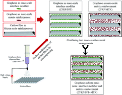
Three different architectural designs are developed for manufacturing advanced multi-scale reinforced epoxy based composites in which graphene sheets and carbon fibers are utilized as nano- and micro-scale reinforcements, respectively. In the first design, electrospraying technique as an efficient and up-scaleable method is employed for the selective deposition of graphene sheets onto the surface of carbon fabric mats. Controlled and uniform dispersion of graphene sheets on the surface of carbon fabric mats enhances the interfacial strength between the epoxy matrix and carbon fibers and increases the efficiency of load transfer between matrix and reinforcing fibers. In the second design, graphene sheets are directly dispersed into the hardener-epoxy mixture to produce carbon fiber/epoxy composites with graphene reinforced matrix. In the third design, the combination of the first and the second arrangements is employed to obtain a multi-scale hybrid composite with superior mechanical properties. The effect of graphene sheets as an interface modifier and as a matrix reinforcement as well as the synergetic effect due to the combination of both arrangements are investigated in details by conducting various physical–chemical characterization techniques. Graphene/carbon fiber/epoxy composites in all three different arrangements of graphene sheets show enhancement in in-plane and out of plane mechanical performances. In the hybrid composite structure in which graphene sheets are used as both interface modifier and matrix reinforcing agent, remarkable improvements are observed in the work of fracture by about 55% and the flexural strength by about 51% as well as notable enhancement on other mechanical properties.
Introduction
Multi-scale reinforced polymeric composite materials with superior mechanical and physical properties as well as multi-functionality have played a key role in rapid technological development in recent years.1,2 Fiber-reinforced thermoset composites with favorable strength-to-weight and stiffness-to-weight ratios have emerged as high-performance structural materials in applications such as wind turbines,3 construction,4 aeronautics,5 and aerospace.6 However, most of the fiber-reinforced composites suffer from poor damage tolerance, impact resistance, delamination strength, and low fracture toughness, which have put serious restrictions on the wider usage of composites in engineering applications and the state-of-the-art load bearing structures.7–9 The performance of fiber-reinforced composites is particularly affected by the properties of the constituent materials and the strength of fiber–matrix interfaces which influence the efficiency of load transfer from the matrix to the reinforcements.10,11 In order to address these issues and achieve the desired performance, there have been several attempts for the enhancement of composite properties which are categorized into two parts: improvement of matrix properties and interface modification.12 One of the main methods for the improvement of the matrix dominant property is based on the dispersion of modifier particles into the matrix of fiber reinforced structures. These modifier particles are divided into two categories which are soft thermoplastic or rubber particles13 and rigid reinforcing particles.14 The incorporation of soft particles into epoxy matrix leads to several processing limitations15 and also the reduction in strength, modulus, stiffness and glass transition temperature (Tg) of matrix.16,17 On the other hand, the integration of rigid fillers into the matrix provides promising modification possibility by improving toughness, stiffness, modulus and Tg values of composites.18 Nevertheless, it was reported in the literature that the soft particles provide higher toughening in comparison to rigid particles.19 When compared to the changes in the matrix dominant properties, the addition of both soft and rigid particles rarely influences the fiber-dominated mechanical properties of composites.20
The mechanical properties and the performance of fiber reinforced composite structures are also affected by interfacial bondings between fiber and matrix in which weak interfacial strength undermines shear stress transfer to fibers thus limiting the performance and the efficiency of composite structures. There are different types of fiber surface modification techniques such as polymeric coating,21 thermal treatment,22 chemical oxidation,23 plasma treatment24 and increasing the surface roughness of carbon fibers25 in order to create better chemical and physical interactions between fiber reinforcement and the polymer matrix. Recently, the integration of reinforcing nanoparticles onto the surface of primary reinforcing fibers has emerged as an alternative technique to enhance the interfacial interaction between the constituents26 and several methods have been developed for the deposition of nanoparticles on the surface of reinforcement micro-fibers.27 Chemical vapor deposition (CVD) is one of the methods that has been applied to grow carbon nanotubes on the surface of carbon fibers to achieve higher interlaminar strength and toughness in multi-layered composites.26 However, the CVD process is time-consuming and energy demanding and, in turn, expensive in pilot-scale production owing to harsh processing conditions and high processing temperature. The processing conditions cause the removal of fiber sizing material applied onto fibers during manufacturing hence deteriorating the original mechanical performance of fibers.28 Furthermore, electrophoresis is another technique for the deposition of electro-active nanoparticles onto the carbon fiber surface by applying DC potential between the carbon fibers and the counter electrode.28 However, this method is limited for certain types of nanoparticles which mostly are carbon-based nanoparticles.29 In another deposition technique, carbon fibers are directly coated by a sizing solution containing nano-particles.30,31 Herein, the viscosity of sizing solution changes by the addition of nanoparticles and also this technique requires further energy and time-consuming drying steps. In addition, sizing material coated on carbon fiber hinders the direct contact between matrix and nanoparticles. The interactions of carbon nanotube with the matrix are extensively studied to improve the characteristic properties of fiber reinforced composites. Graphene has also started receiving attention as modifier/reinforcement in polymers and polymeric composites due to being one of the strongest materials ever measured with a theoretical Young's modulus of 1060 GPa and an ultimate strength of 130 GPa.32,33 In addition, high specific surface area of graphene sheets results in stronger interfacial interactions and better load transfer between polymeric matrix and reinforcement particles which make them suitable candidate for nanocomposite fabrication.34 It is known that nanocomposites reinforced by graphene-based materials even at very low loadings have shown great influence on mechanical performance, thermal, electrical conductivity, and flame retardancy in comparison of unmodified polymers.35,36 It should be noted that in the majority of these works, the graphene was used as a primary reinforcement in the polymeric matrix without the presence of continuous fiber reinforcement and hence the reported enhancements in mechanical properties are much easily achievable in comparison to continuous fiber reinforced polymeric composites with nanophase integration.
In the present work, electrospraying (or electrohydrodynamic spraying) technology is used for the deposition of thermally exfoliated graphene oxide (TEGO) sheets on the surface of carbon fibers for the modification of carbon fibers/epoxy matrix interface without damaging the original properties of carbon fibers. To the best of our knowledge, there is no published work for the deposition of graphene sheets on the surface of carbon fiber by electrospraying process. This technique is fast, efficient, cost-effective and easily up-scalable process since it is possible to control the amount of nanoparticles precisely, coating rate, the position of coating and final dispersion state of deposited reinforcing particles. TEGO as nano reinforcement was selectively dispersed into epoxy/carbon fiber composite with three different arrangements. In the first arrangement, TEGO was dispersed onto the surface of reinforcing carbon fibers via electrospraying to enhance interfacial interaction between fiber and matrix. In the second arrangement, hardener containing TEGO was prepared by sonication process and then mixed with epoxy resin. The final mixture is used to impregnate the stack of dry carbon fiber through the vacuum infusion process thereby producing carbon fiber reinforced composites. In the last arrangement, the combination of the first and the second arrangements was employed to obtain a multi-scale hybrid composite with superior mechanical properties. In this hybrid design, the failure behavior of carbon fiber reinforced epoxy matrix composites structures is improved by multi-scale mechanisms where traditional continuous carbon fiber reinforces the composite structure in micron-scale while nanoparticles reinforce the matrix and carbon fiber–matrix interface in nanoscale.
Experimental
Materials
Materials used are N,N dimethyl formamide (DMF, Sigma-Aldrich, 99%), thermally exfoliated graphene oxide (TEGO) Grade-2 (purchased from Nanografen Co.), Araldite LY 564 resin, Hardener XB 3403, uniaxial carbon fabrics of Metyx company with the average weight of 310 g m−2 (300 g m−2 800 Tex 12 K along 0° direction, and 10 g m−2 68 Tex E-glass along 90° direction).
Selective dispersion of TEGO as matrix and interface reinforcing agents
Two different approaches were employed to integrate TEGO sheets into a composite structure. In the first approach as schematically represented in Fig. 1a, TEGO sheets were exfoliated and dispersed into low viscosity hardener liquid by using probe sonicator (Qsonica, Q700) for 10 min at room temperature, and then bath sonication (Sonorex Digital 10P, Bandelin GmbH, Germany) was applied for complete exfoliation and stabilization of the TEGO-containing hardener for 24 h at 40 °C.
 |
| | Fig. 1 Schematic representation of (a) dispersion of TEGO sheets into the epoxy matrix to obtain nano-reinforced matrix and (b) dispersion of TEGO sheets as an interface reinforcement agent by electrospraying process. | |
In the second approach, 0.1 wt% TEGO sheets were directly dispersed in DMF by means of probe and bath sonication to obtain well-dispersed electrospray solutions for the coating process. Then, the prepared suspension was loaded into electrospraying syringe and subsequently sprayed onto both surfaces of dry carbon fiber ply under an electrical voltage of 15 kV, solution flow rate of 100 µl min−1 and spraying distance of 15 cm (Fig. 1b). In order to spray TEGO sheets on the entire surface area of carbon fabric/ply, electrospraying system was mounted on a homemade fully automated two axis router system with variable movement speed in both x- and y-directions so that spraying can be performed at any desired locations.
Fabrication of multi-scale reinforced epoxy composites
As the first step, the classical molding technique was employed to fabricate TEGO reinforced composite samples to find the optimum concentration of dispersed TEGO sheets into the epoxy matrix. To this end, mixtures of degassed resin and hardener system with different TEGO sheet concentrations were poured into Teflon molds, vacuumed in a vacuum oven to remove the entrapped air bubbles from the resin, cured at 75 °C for 24 h, and then post cured at 90 °C for 24 h. The molded samples were processed into three-point bending test specimens with the length, width, and the thickness of 100 mm, 14 mm, and 3 mm, respectively.
As the second step, composite laminates with three different multi-scale reinforcement architectures were produced to scrutinize how the method of integrating TEGO sheets into carbon fiber reinforced epoxy matrix composite affects the mechanical properties of manufactured composites. To this end, in the first design, TEGO sheets were electrosprayed onto both surfaces of unidirectional dry carbon fiber plies as an interface modifier. Subsequently, electrosprayed carbon fiber plies are stacked into a [90°/0°]S configuration and then impregnated by a degassed neat epoxy resin-hardener system as shown in Fig. 2. The TEGO weight percentage in this composite laminate is about to be 0.01 wt%. In the second design, TEGO sheets were dispersed directly into epoxy and hardener mixture to act as a matrix reinforcement agent. Neat carbon fiber plies with [90°/0°]S stacking sequence were also impregnated by this TEGO integrated resin system after degassing. The weight percentage of TEGO in the epoxy-hardener mixture is 0.05 wt% and the total weight percentage of TEGO in the manufactured carbon fiber reinforced composite is 0.01 wt%. The third design is the combination of the first and the second approach such that both TEGO deposited carbon fiber plies with the same stacking sequence as before and TEGO containing epoxy-hardener mixtures were used to fabricate composite laminates. The total weight percent of TEGO in this combination is 0.02 wt%. In each design, stacked carbon fiber plies (neat or TEGO deposited) were impregnated by degassed resin using vacuum infusion method. The dimension of the manufactured composite laminates is 40 cm × 35 cm × 0.12 cm.
 |
| | Fig. 2 Schematic representation of composite manufacturing by vacuum infusion, (a) stacking sequence where the yellow region indicates the cut specimen for mechanical tests, and (b) the vacuum infusion system. | |
The volume fractions of carbon fiber in the composite laminates were calculated by burning test to be nearly 70% of overall composites. The composite panels were cut to the size of flexural, tensile, DMA and impact test specimens: namely, 8 cm × 1.5 cm × 0.12 cm, 20 cm × 2.5 cm × 0.12 cm (with the gage length of 15 cm), 6.5 cm × 1 cm × 0.12 cm and 6 cm × 1 cm × 0.12 cm, respectively. To avoid the breakage of tensile specimens at grip locations, aluminum tabs with a dimension of 3 cm × 2.5 cm × 0.1 cm were bonded to the both ends of specimens by using two-component room temperature curing epoxy system (Araldite, 2011).
Characterization
The morphologies of TEGO before and after dispersion and of carbon fibers with and without graphene deposition were analyzed by a Leo Supra 35VP Field Emission Scanning Electron Microscope (SEM) and the cross-sectional area of specimens after breakage was analyzed by a JEOL JSM 6010 Scanning Electron Microscope (SEM). Raman spectroscopy was used to analyze the structural changes of graphene layers and carbon fibers by using a Renishaw inVia Reflex Raman microscopy system with the laser wavelength of 532 nm at room temperature in the range of 100–3500 cm−1. X-ray photoelectron spectroscopy (XPS) measurements were conducted by using a Physical Electronics Quantum 2000 Scanning ESCA Microprobe. The mechanical tests were conducted by ZWICK Proline 100 Universal Test Machine (UTM) with 10 and 100 kN load cells for 3-point bending and tensile tests, respectively, with a constant cross-head speed of 2 mm min−1. The three-point bending and tensile tests on the relevant specimens were performed in accordance with ASTM D790-03 and ASTM D5083-02 standards, respectively. The axial and transverse strains were measured during tensile tests with two clip-on strain gage extensometers (Epsilon, Tech. Corp.). To scrutinize the failure mechanisms of manufactured composites, a detailed fractographic analysis was carried out on the cross section along the length of the specimen through thickness following the detailed procedure given in our previous publication.37 Charpy impact tests of the composites were performed on an instrumented CEAST Resil impactor apparatus at a speed of 2.9 m s−1 by using a pendulum with nominal energies of 4 J. The measurements were conducted according to ASTM D256 method by using rectangular unnotched specimens.
Results and discussion
Morphologies and properties of TEGO
The surface chemistry of graphene significantly influences its dispersion in the epoxy matrix hence affecting the amount of improvement to be achieved in the mechanical performance of composites. Specifically, carbon/oxygen ratio of graphene and the viscosity of hardener-epoxy mixture are two important parameters which directly affect the dispersion behavior of graphene sheets. In order to prevent aggregations of graphene sheets and reduce the defects in the matrix, TEGO is preferred as a reinforcing agent in the present work since thermal treatment removes most of oxygen groups from the surface of the graphene oxide, increases exfoliation ratio and changes the hydrophilic nature of graphene oxide.38 The oxygen content of TEGO determined through XPS analysis is about 6% (provided by the manufacturer) and this oxygen amount is sufficient to provide proper interactions between TEGO and amine-based hardener or solvents.39 SEM micrographs in Fig. 3a and b reveal the layered structure and worm-like appearance of as received TEGO sheets before applying any sonication. However, after the sonication, the complete dispersion and layer separation of TEGO in the DMF can be seen clearly in Fig. 3c. In addition, as received TEGO sheets have a density of 0.022 g ml−1 and average layer number of 25 (provided by the manufacturer).
 |
| | Fig. 3 SEM micrographs of (a, b) as received TEGO particles at different magnifications and (c) TEGO sheets after the dispersion into DMF by sonication. | |
TEGO as a primary reinforcement
Mechanical performance of epoxy/TEGO nanocomposites.
In the initial step of composite production, the optimum amount of TEGO in the epoxy matrix was determined by applying classical molding technique. Fig. 4a shows flexural stress–strain curves for the neat specimen and TEGO reinforced epoxy specimens with three different TEGO concentrations of 0.0125 wt%, 0.025 wt% and 0.05 wt%. Fig. 4b and c exhibit changes in flexural modulus and strength of epoxy/TEGO nanocomposites as a function of TEGO concentration. In both flexural modulus and strength values, a gradual increase is observed until the 0.025 wt% TEGO and the maximum mechanical performance is reached at the concentration of 0.05 wt% TEGO. In addition, 0.05 wt% of TEGO is the highest concentration for homogeneous dispersion and complete exfoliation during the sonication process. Otherwise, the presence of unexfoliated particles in composite structure creates stress concentration sites, which degrade the mechanical performance of the structure. Table 1 gives the improvement percentages of flexural modulus and strength of TEGO reinforced epoxy specimens. The highest increase in flexural modulus is ∼85% and the highest increase in flexural strength is ∼64%, which are achieved by the addition of 0.05 wt% TEGO. Considering the limitation in dispersibility of TEGO in hardener due to the notable increase in its surface area after being exfoliated, and the corresponding highest mechanical performance achieved, 0.05 wt% was chosen to be maximum achievable TEGO concentration that can be uniformly and properly dispersed in epoxy matrix and deemed to be optimum concentration as a co-reinforcement together with carbon fibers in multi-scale composite systems.
 |
| | Fig. 4 (a) Flexural stress–strain curves of neat and TEGO/epoxy composite specimens with different TEGO contents, (b) flexural modulus improvement and (c) flexural strength improvement graphs as a function of TEGO content. | |
Table 1 Flexural strength and modulus values and their improvement percentages of neat and TEGO/epoxy composites
| |
Neat |
0.0125 wt% |
0.025 wt% |
0.05 wt% |
| Flexural strength (MPa) |
75 ± 2 |
109 ± 5 |
117 ± 3 |
123 ± 2 |
| Flexural strength improvement (%) |
— |
45 |
56 |
64 |
| Flexural modulus (GPa) |
1.68 ± 08 |
2.53 ± 0.3 |
3 ± 0.1 |
3.1 ± 0.1 |
| Flexural modulus improvement (%) |
— |
51 |
78 |
85 |
Fracture surface analysis of neat specimen and TEGO/epoxy composite.
Examining the morphology of fracture surfaces helps understand the dispersion behavior of TEGO sheets and the failure mechanisms in the crack regions. Fig. 5 exhibits SEM images for the fracture surfaces of the neat specimen and 0.05 wt% TEGO/epoxy composite after 3-point bending tests. The fracture surface of the neat specimen presented in Fig. 5a and b at different magnifications is flat and smooth which is the characteristic of brittle fracture behavior and points to the low fracture toughness of the neat specimen. In contrast, the fracture surface of composite reinforced by 0.05 wt% TEGO is significantly rougher than that of the neat specimen as seen in Fig. 5c and d. The increase in the roughness of fracture surface associated with the creation of additional surfaces due to the crack deflection, tilting and twisting during fracture is common for particle reinforced composites.40 The creation of rough surfaces can facilitate the dissipation of energy during the breakage of composites, which bespeaks the reinforcement effect of TEGO sheets in the epoxy matrix. Here, the toughness increases since TEGO sheets are tightly held to the resin by strong interfacial bonding between TEGO and epoxy matrix. Furthermore, uniform roughness is observed in Fig. 5c and d, which indicates homogeneous dispersion and complete exfoliation of TEGO sheets in the matrix without any noticeable aggregations.
 |
| | Fig. 5 SEM images of the fracture surface of specimens after three-point bending tests (a, b) neat epoxy, and (c, d) 0.05 wt% TEGO/epoxy composite. | |
Modification carbon fiber–epoxy matrix interface by electrospray deposition of TEGO.
Electrospraying method is employed for the deposition of TEGO sheets onto the surface of carbon fabric mats. This method is a solvent based technology in which TEGO sheets are initially dispersed into a suitable solvent and then atomized by means of electrical forces. In the electrospraying process, high electric field force is applied between the nozzle and the carbon fiber mat thus breaking up the initial droplet formed at the tip of the nozzle into fine electrically charged droplets.41 The electric field between the nozzle and the target provides a guided path for these fine droplets thereby leading to uniform, homogeneous, and target localized coverage of carbon fiber mat by nano-reinforcing particles. At this point, the crucial parameter is the preparation of TEGO suspension solutions in which TEGO sheets are fully exfoliated and can be stable in suitable time scale. The complete exfoliation and stable suspensions are just achieved by multi-step and extensive sonication processes. Fig. 6a and b reveal smooth surface and parallel superficial grooves of as-received carbon fabric mat at different magnifications while Fig. 6c and d show very thin and transparent graphene layer formation on the surface of carbon fibers after TEGO dispersion. In addition, Fig. 6e provides a low magnification image for carbon fabric surface after electrospraying treatment wherein one can see that TEGO sheets cover the fabric surface discretely and uniformly. It is noted that electrospraying process does not damage the consistency of fibers since carbon fibers still preserve original surface morphology after solution spraying. Extremely thin graphene layers (with a very large surface area to volume ratio) have strong tendency to attach on active surfaces due to attractive interfacial forces (i.e., van der Waals forces, electrostatic interactions and dangling bonds, among others).42 These interactions are strong enough to deform graphene sheets in an out-of-plane direction whereby graphene sheets can conform onto the surface geometry of carbon fiber as seen in Fig. 6c and d, and to prevent graphene sheets from falling off the surfaces of carbon fiber strands during the handling and processing. The presence of graphene sheets on the surface of carbon fibers enhances the interfacial strength between fibers and polymeric matrix by increasing the surface roughness and surface energy as well as providing chemical and hydrogen bonding between matrix and reinforcement due to the presence of oxygen functional groups on the surface of TEGO sheets and carbon fibers.
 |
| | Fig. 6 SEM images of carbon fabric mat (a, b) as-received, (c, d) after electrospraying of TEGO sheets and (e) low magnification image of carbon fabric with electrosprayed TEGO. | |
In order to evaluate the effect of electrospraying process on the structural changes and surface chemistry of the carbon fibers, RAMAN and XPS analysis were performed on untreated and electrosprayed fibers. Fig. 7 presents the Raman spectra of as received carbon fiber, TEGO sheets, and TEGO sprayed carbon fibers. Carbon fiber exhibits two main characteristic Raman peaks which are D peak at ∼1353 cm−1 corresponding to disordered carbon structure and G peak at ∼1584 cm−1 attributed to graphitized carbon and in-plane vibrations of sp2 bonded carbon atoms.43 On the other hand, pristine TEGO has D, G and 2D peaks, which lie at around 1348 cm−1, 1575 cm−1, and 2720 cm−1, respectively. After the deposition of TEGO sheets on the surface of carbon fibers, the characteristic peaks of graphene become dominant and 2D band appears at 2721 cm−1 whose intensity directly depends on the number of graphene layers.44 This observation indicates that carbon fiber surface is covered by graphene sheets. It is known from literature that the ratio of D and G peak intensities (ID/IG) gives defect concentration in carbonic structure, and higher ID/IG stands for the higher sp3/sp2 ratio in carbonic structure.43 Table 2 compares the intensities of Raman peaks and ID/IG ratios of pristine TEGO, pristine carbon fiber and TEGO sprayed carbon fiber. Low ID/IG ratio for TEGO sheets confirms that TEGO sheets are mostly in graphitic structure and carbon atoms mainly are in sp2 type bond geometry, which is responsible for high conductivity of TEGO sheets. On the other hand, neat carbon fiber has higher ID/IG ratio about 0.96 indicating the dominance of sp3 bonds. After the coverage of TEGO sheets on carbon fiber mats, ID/IG ratio significantly decreases since Raman peaks of graphene become prominent. Furthermore, IG/I2D ratio directly depends on the number of graphene layers and indicates the coating thickness. After the appearance of 2D peak in Raman spectra of TEGO coated carbon fibers, IG/I2D ratio is about 1.84 which is lower than the ratio of pristine TEGO about 1.99. This indicates that graphene layers are dispersed on the carbon fiber mat under electric field during electrospraying process thereby covering the surface of carbon fibers, but graphene sheets still preserve its multi-layer structure. Consequently, Raman spectroscopy analysis proves TEGO coating on carbon fiber surface since Raman signals are directly collected from the specimen surface.
 |
| | Fig. 7 Raman spectra of as received carbon fiber, TEGO sheets, and TEGO sprayed carbon fiber. | |
Table 2 The intensities and peak positions of D and G bands, and ID/IG ratios of pristine carbon fiber, TEGO sprayed carbon fiber and TEGO sheets
| |
D band intensity (a. u.) |
G band intensity (a. u.) |
I
D/IG |
2D band peak intensity (a. u.) |
I
G/I2D |
| As received carbon fiber |
7763 |
8073 |
0.96 |
— |
— |
| TEGO sprayed carbon fiber |
2016 |
8840 |
0.22 |
4808 |
1.84 |
| TEGO sheets |
4193 |
19 821 |
0.21 |
9968 |
1.99 |
XPS is a quantitative surface analysis technique that is used to evaluate the elemental composition and functional groups of as received carbon fiber, TEGO sheets, and TEGO sprayed carbon fibers. In order to determine oxygen-containing functional groups, C 1s and O 1s signals were analyzed at binding energies of ∼286 and ∼532 eV, respectively, and functional groups were assigned based on the characteristic binding energy of each element.45 The intensities of C 1s and O 1s peaks for each material were compared in the XPS survey scan spectra as seen in Fig. 8. C/O ratios and types of functional groups with their atomic percentage calculated from XPS results are presented in Table 3. C/O ratios of as received carbon fiber, TEGO and TEGO sprayed carbon fiber are 3.6, 14.8 and 5.0, respectively. The changes in C/O ratio indicate that the deposition of TEGO sheets on carbon fiber surface changes the elemental composition and thus the carbon content on the surface of carbon fiber increases. In Table 3, the C 1s envelope of TEGO sheets has mainly sp2 carbon bonds about 77.3 at% because of a hexagonal ring of six carbon atoms in TEGO structure. The C 1s peaks of carbon fibers contain C–C bonds at 284.8 eV, C–O bond at 286.4 eV and O
C–O bond at 289 eV with the atomic weight percentages of 41, 34.4 and 3, respectively and no sp2 hybridized carbon atoms (C–C) are detected on the surface of carbon fibers. After the electrospraying of TEGO sheets on carbon fiber surface, sp2 carbon atoms appear in the structure with the atomic weight percentage of 4.0. The deconvoluted O 1s XPS spectrum of TEGO sprayed carbon fiber exhibits C
O bonds at 531 eV due to the coverage of TEGO sheets. XPS analysis also confirms the coating of TEGO sheets on carbon fiber mats quantitatively.
 |
| | Fig. 8 XPS survey scan spectra of as received carbon fiber, TEGO, and TEGO sprayed carbon fiber. | |
Table 3 XPS spectra results of C 1s and O 1s for TEGO, carbon fiber, and TEGO sprayed carbon fiber
| Sample |
XPS C 1s spectra |
XPS O 1s spectra |
C/O ratio |
| Peak attribution |
Binding energy (eV) |
Atomic% |
Peak attribution |
Binding energy (eV) |
Atomic% |
| TEGO sprayed carbon fiber |
C–C |
284.8 |
48.5 |
C–O |
532.9 |
15.3 |
5.0 |
| C–O |
286.4 |
28.4 |
C O |
531.0 |
1.4 |
|
O C–O |
288.9 |
1.4 |
|
|
|
|
| C–C sp2 |
284.1 |
4.0 |
|
|
|
|
| As received carbon fiber |
C–C |
284.8 |
41.0 |
C–O |
532.8 |
21.7 |
3.6 |
| C–O |
286.4 |
34.4 |
|
|
|
|
O C–O |
289.0 |
3.0 |
|
|
|
|
| TEGO |
C–C |
284.8 |
3.1 |
C–O |
532.4 |
4.3 |
14.8 |
| C–O |
286.3 |
3.1 |
C O |
530.6 |
1.6 |
|
O C–O |
288.9 |
4.25 |
|
|
|
|
| C–C sp2 |
284.1 |
77.3 |
|
|
|
|
C O |
287.8 |
1.0 |
|
|
|
|
Mechanical performance of multi-scale reinforced composites
Four different composite samples were designed and fabricated through vacuum infusion technique: (1) conventional epoxy/carbon fiber composites without any TEGO sheets as a reinforcement (CFRP), (2) epoxy/carbon fiber composite with 0.01 wt% TEGO as an interface reinforcement (CFRP/INT), (3) epoxy/carbon fiber composite with 0.01 wt% TEGO as a matrix reinforcement (CFRP/MTX) and, (4) epoxy/carbon fiber composite fabricated by the addition of both 0.01 wt% TEGO as an interface reinforcement and 0.01 wt% TEGO as an matrix reinforcement (CFRP/INT + MTX). The performances of these four arrangements were evaluated by in- and out-of-plane mechanical tests and impact tests to determine the ideal multi-scale reinforcement configuration.
Flexural properties.
Flexural properties are key parameters for the evaluation of mechanical performance and understanding the interactions between matrix and fiber at the interface in composite materials. The representative flexural stress vs. strain curves obtained from 3-point bending tests for four different specimens are shown in Fig. 9a. Three different flexural properties were obtained from these tests: that is to say, flexural modulus (FM) as a parameter for the tendency of the composite material to bend, flexural strength (FS) as a factor indicating the resistance of materials against the fracture, and the work of fracture (WOF) scaling the energy dissipated in the course of fracture of the specimen. The flexural test results show that FM, FS and WOF values of the multi-scale epoxy composites reinforced by any arrangement of nano-reinforcements are notably higher than those of conventional carbon fiber/epoxy composite signifying the efficacy of engineered nano-integration. In comparison of the results of CFRP, FM, FS and WOF values of interface modified CFRP (CFRP/INT) specimens produced by electrospraying of TEGO sheets on carbon fiber mats increase about 18.5%, 16.2%, and 31%, respectively. TEGO sheets used as an interface modifier have matrix compatible functional groups that enhance the interfacial properties and subsequently improve the interfacial bonding strength thereby leading to more effective load distribution among phases, and also inhibition of micro cracks at the interface. In the case of matrix modified CFRP specimens fabricated by direct mixing of TEGO sheets in epoxy-harder mixture (CFRP/MTX), FM, FS and WOF are improved by about 15%, 20.5%, and 22.3%, respectively. The CFRP/MTX specimens have notably lower WOF improvement percentage than CFRP/INT specimens, which stems from different fracture mechanisms between these two composite arrangements. Namely, in the CFRP/INT specimens, fracture occurs at higher strain values as seen in Fig. 9a and fiber breakage becomes dominant during failure mechanism. On the other hand, as for CFRP/MTX specimens, the presence of TEGO sheets in the matrix increases the matrix modulus whereby the matrix carries higher loads with respect to the matrix of CFRP/INT specimens in accordance with the rule of the mixture in composite materials. As a result, the higher amount of cracks occurs in matrix and failure occurs at lower strain values as can be seen in Fig. 9a, and 10b and c. During 3-point bending tests, matrix cracking dissipates less energy compared to carbon fiber breakage that explains the difference between WOF values of these two types of composites. As for the composites with multi-scale and multi-arrangement reinforcements (CFRP/INT + MTX) in which both matrix and interface of composite structure are modified by TEGO sheets, due to synergic effect of two different TEGO arrangements, FM, FS and WOF are enhanced by 31.1%, 51.2%, and 55%, respectively. In CFRP/INT + MTX specimens, compared to CFRP/MTX specimens, the higher portion of applied load is transferred to fibers due to the modified interface, and so, both matrix cracking and fiber failure contribute to the failure of structure because of enhanced interface properties and more efficient load transfer from matrix to the reinforcing fibers. Therefore, TEGO sheets acting as a reinforcing agent in both matrix and fiber structure in multi-scale composite design increase WOF values due to the higher energy dissipation.
 |
| | Fig. 9 (a) Flexural stress–strain curves, (b) tensile stress–strain curves (c) Poisson's ratio versus axial strain of carbon fiber-reinforced epoxy specimens with different TEGO arrangements and (d) the window of percentage improvement in mechanical performance with respect to the properties of CFRP. | |
 |
| | Fig. 10 SEM images of cross-sectional area of specimens after flexural failure (a) CFRP, (b) CFRP/INT, (c) CFRP/MTX, and (d) CFRP/INT + MTX. | |
Tensile properties.
The effect of TEGO on tensile properties of composites produced by different arrangements was investigated by applying an axial load by UTM. Fig. 9b exhibits the representative tensile stress and strain curves of four carbon fiber epoxy composites with different nano-reinforcement configurations. As can be obviously observed in Fig. 9b, for any nano-reinforcement configurations, tensile modulus (TM) and tensile strength (TS) of nano-reinforced multi-scale epoxy composites are higher than those of conventional carbon fiber/epoxy composites. TM and TS values of CFRP/INT specimens are enhanced by about 15.5% and 9.6%, respectively because of improved interfacial bonding strength in the presence of interface modifier particles. On the other hand, TM and TS of CFRP/MTX specimens are improved by about 20.3% and 17.4%, respectively due to the contribution of TEGO sheets to load distribution and their ability to enhance the matrix properties. In CFRPs, the main load carrying constituent along the tensile direction is carbon fibers. Therefore, expectedly, the improvement in the tensile properties due to the interface modification by TEGO is not as notable as that in flexural properties since the TEGO does not improve the tensile properties of carbon fiber. As in the case of the matrix modification, since the TEGO significantly modifies the matrix properties in a volumetric manner recalling Fig. 4, the improvement is observed regardless of loading direction, namely, flexural and tensile. In composites with the multi-scale and multi-arrangement of nano-reinforcements (CFRP/INT + MTX), the improvement in TM and TS are about 20.3% and 19.4%. These values are rather close to those obtained for CFRP/MTX specimens given that in the tensile mode, the volumetric matrix properties are dominant over interface properties between the matrix and the carbon fiber.
During tensile tests, axial strain (εx) and transverse strain (εy) were monitored by axial and transversal extensometers simultaneously wherefrom Poisson's ratio, νxy = −εy/εx corresponding to a contraction in y-direction when an extension is applied in x-direction, is computed and then plotted as a function of axial strain in Fig. 9c. Poisson's ratio increases rapidly for all specimens with the rise in the axial strain and then reach a plateau. This initial rise in the Poisson's ratio is due to the fact that lateral strain increases nonlinearly as a function of applied axial strain. As seen from Fig. 9c, each composite configuration acquires different plateau behavior. One may observe that in the region where the Poisson's ratio is of an increasing trend, for a given axial strain value, Poisson's ratios of the nano-integrated composite specimens are smaller than the Poisson's ratio of the neat specimen. This bespeaks that the stiffness of the nano-integrated composites increases thereby reducing the lateral deformation. The comparison of the results of nano-integrated composite specimens indicates that the matrix reinforcement with the graphene is more effective in increasing the stiffness of the composite structure. Moreover, the results of Poisson's ratio are in agreement with the outcomes of other mechanical tests where the specimens with TEGO as both matrix reinforcement and interface modifier have higher mechanical performance due to strong interfacial bonding between nano-reinforced matrix, and surface modified carbon fibers, enabling improved load transfer across the composites.
Charpy impact test.
Charpy impact test is used to determine the impact strength or energy absorbed during the fracture of specimens under high strain rates. The improvement in the impact strength of CFRP/INT, CFRP/MTX, and CFRP/INT + MTX specimens are about 16.6%, 25.3%, and 29.9%, respectively, compared to unmodified CFRP specimens. The fact that the CFRP/MTX composite specimens yield higher impact strength than CFRP/INT specimens and also the negligible difference in the impact strengths of CFRP/MTX and CFRP/INT + MTX specimens are evidence for matrix toughening effect of graphene sheets. Expectedly, CFRP/INT specimens do not have as much increase in the impact strength as two others since nano graphene as interface modifier is more effective for load transfer between carbon fibers and matrix and do not contribute to the toughness of the composites at high strain rates. For all composites, the summary of the results of mechanical tests and achieved percent improvements in mechanical properties with respect to neat CFRP composites is given in Table 4 and Fig. 9d, respectively. As can be clearly seen in Fig. 9d, the integration of TEGO sheets in any arrangements as matrix reinforcement or a carbon fiber epoxy matrix interface modifier widen the mechanical performance window of the composite structure. In addition, specimens with TEGO sheets as an interface modifier show higher FS and WOF values compared to the specimens with TEGO used as a matrix reinforcing agent. On the other hand, specimens with TEGO as matrix reinforcement show greater FM, TS, TM and impact strength (IMP) values compared to the interface modified specimens. Furthermore, the synergic effect of TEGO integration as matrix reinforcement and interface modifier results in a wider window of the mechanical performance of composite structure and superior performance in all mechanical tests.
Table 4 Summary of mechanical properties of carbon fiber reinforced specimens
| |
CFRP |
CFRP/INT |
CFRP/MTX |
CFRP/INT + MTX |
| Flexural strength (MPa) |
730 ± 19 |
865 ± 28 |
853 ± 22 |
1104 ± 30 |
| Flexural strength improvement (%) |
— |
18.5 |
15 |
51.2 |
| Flexural modulus (GPa) |
74.2 ± 3 |
86.2 ± 2 |
89.4 ± 1 |
97.3 ± 5 |
| Flexural modulus improvement (%) |
— |
16.2 |
20.5 |
31.1 |
| WOF (kJ m−2) |
18.0 ± 0.6 |
23.5 ± 0.4 |
22.3 ± 0.2 |
27.9 ± 0.8 |
| WOF improvement (%) |
— |
31 |
24 |
55 |
| Tensile strength (MPa) |
670.8 ± 32 |
735.5 ± 28 |
787.9 ± 31 |
800.9 ± 14 |
| Tensile strength improvement (%) |
— |
9.6 |
17.4 |
19.4 |
| Tensile modulus (GPa) |
18.7 ± 0.5 |
21.6 ± 0.2 |
22.5 ± 0.5 |
22.5 ± 0.3 |
| Tensile modulus improvement (%) |
— |
15.5 |
20.3 |
20.3 |
| Impact strength (kJ m−2) |
89.3 |
104.1 |
111.9 |
116.0 |
| Impact strength improvement (%) |
— |
16.6 |
25.3 |
29.9 |
Microscopic observation and failure mechanisms
A fractographic analysis was performed on the cross section of flexural test specimens (bounded by length and the thickness) to scrutinize the effect of different nano-reinforcement configurations on the failure mechanisms of composites. Fig. 10 represents SEM images of cross-sectional areas of flexural test specimens after cutting and polishing steps. The cross sections correspond to the right-hand side view shown in Fig. 2a. In these specimens, there are two different orientation of fiber reinforcement; fibers oriented in a parallel manner to the cross section plane at outer layers and fibers oriented perpendicularly to cross section plane in the middle of specimens. Fig. 10a shows the cross section of neat glass CFRP specimen after the breakage under flexural load. It can be seen that the first layer of fibers directly subjected to the applied load is completely broken down and the delamination of first and second layers of fibers is observed in the fractographic analysis. This delamination in the neat CFRP composite specimen confirms the relatively weak interfacial interaction between reinforcing fibers and epoxy matrix, which triggers the separation of carbon fibers from matrix under the applied flexural load. Fig. 10b exhibits the cross section of CFRP/INT specimen in which the outer layer of fibers is crushed and broken down under the applied load while delamination does not occur, and the first and the second layers are well connected to each other after the failure. The absence of delamination in CFRP/INT specimen indicates superior interfacial bonding between carbon fibers and epoxy matrix due to the modification of interface by electrosprayed TEGO sheets. The failure behavior of CFRP/MTX is presented in Fig. 10c wherein fractures occur in the form of matrix cracking, and fiber breakage does not take place in the first layer of fibers, unlike other specimens. The failure in the form of matrix cracking in CFRP/MTX specimen is due to the increase in elastic modulus of the matrix, which enables the matrix to bear the higher load in comparison to specimens with neat epoxy as matrix whereby the higher amount of cracks occurs in the matrix. Fig. 10d shows the fractured cross section of a CFRP/INT + MTX specimen after flexural failure where one can see fiber breakage of the first layer as well as some matrix cracking. In addition, a few minor delaminations are observed albeit the higher flexural load imposed on this family of the specimen for fracture as seen Fig. 9a. The higher flexural load required for the fracture of CFRP/INT + MTX specimen under 3-point bending test deteriorates the interfacial bonding between carbon fibers and matrix thereby leading to partial delamination in the structure. These fractographic analyses provide an important insight as to the nature of the failure of specimens and the effect of TEGO sheets on interfacial interactions and load distribution between polymeric matrix and reinforcing components in each composite structure.
Conclusions
Electrospraying, which is a fast, efficient and easily up-scalable process, is employed for the deposition of graphene sheets onto carbon fabric mats to strengthen the interfacial interactions between carbon fiber reinforcement and epoxy matrix. The integration of graphene sheets on carbon fiber interface enhances the efficiency of load transfer from matrix to reinforcing fibers whereby the mechanical performance of composite structure notably improves due to the stronger interfacial strength. In addition, the results of XPS and Raman spectroscopy analyses confirm that the deposition of graphene layers via electrospraying technique does not affect the chemical structure and properties of carbon fibers adversely, and the carbon fabric mat preserves its structural consistency during composite manufacturing steps.
In order to obtain high mechanical performance with optimum graphene concentration, the effect of graphene sheets as a primary reinforcement on the properties of the epoxy matrix was initially investigated in details by three-point bending tests. The flexural strength and modulus of graphene–reinforced epoxy composites with a low concentration of 0.05 wt% TEGO produced by using classical molding technique are improved about 64% and 85%, respectively. Well-dispersed and stable TEGO containing epoxy hardener was prepared by sonication technique to prevent the agglomeration of graphene sheets in an epoxy matrix and structural defect formation. Then, a formulated mixture of graphene and epoxy was infused into the [0/90]S stack using vacuum infusion to produce carbon fiber reinforced epoxy composites. The integration of graphene into the carbon fiber reinforced composite in the form of matrix reinforcement leads to appreciable enhancement in the mechanical performance of manufactured composite structures. Furthermore, the utilization of graphene sheets as both interface modifier and matrix reinforcement shows a synergetic effect thereby resulting in excellent improvements in the mechanical performance of the hybrid composite structure. Namely, when compared to unmodified composite structure, flexural strength, modulus and work of fracture are enhanced by about 51.2%, 31.1%, and 55%, respectively while tensile strength, modulus, and impact strength are augmented by about 19.4%, 20.3%, and 29.9%, respectively. The detailed fractographic analyses were performed to establish an understanding on different fracture mechanisms involved in the failure of specimens under flexural loads and the effect of selective TEGO dispersion on composite performance and especially the interfacial interactions between carbon fibers and epoxy matrix. This novel architectural design involving multi-scale reinforced epoxy composite structures and nano-scale modified carbon fiber epoxy interface provides a readily scalable process for industrial applications and can be further explored for the development of lighter advanced structural composites. We consider our conclusions to be a stepping-stone for our future work for multi-scale composite structures that will focus on the dynamical-mechanical and electrical–thermal properties of these developed hybrid structures in the next report. The findings of this study are believed to contribute to the state of the art significantly given that the notable improvements are achieved in the presence of already strong carbon fiber reinforcements.
Acknowledgements
The authors gratefully acknowledge the financial support of the Scientific and Technical Research Council of Turkey (TUBITAK) with the project numbers of 112M357.
Notes and references
- M.-Y. Lyu and T. Choi, Int. J. Precis. Eng. Manuf., 2015, 16, 213–220 CrossRef.
- G. Mittal, V. Dhand, K. Y. Rhee, S.-J. Park and W. R. Lee, J. Ind. Eng. Chem., 2015, 21, 11–25 CrossRef CAS.
- C. Kong, J. Bang and Y. Sugiyama, Energy, 2005, 30, 2101–2114 CrossRef CAS.
- T. C. Triantafillou and N. Plevris, Mater. Struct., 1992, 25, 201–211 CrossRef CAS.
- E. C. Botelho, R. A. Silva, L. C. Pardini and M. C. Rezende, Mater. Res., 2006, 9, 247–256 CAS.
- A. Toldy, B. Szolnoki and G. Marosi, Polym. Degrad. Stab., 2011, 96, 371–376 CrossRef CAS.
- P. J. Hine, M. Bonner, I. M. Ward, Y. Swolfs, I. Verpoest and A. Mierzwa, Composites, Part A, 2014, 65, 19–26 CrossRef CAS.
- G. W. Beckermann and K. L. Pickering, Composites, Part A, 2015, 72, 11–21 CrossRef CAS.
- J. S. Monfared Zanjani, B. S. Okan, I. Letofsky-Papst, Y. Menceloglu and M. Yildiz, RSC Adv., 2015, 5, 73133–73145 RSC.
- A. Gopinath, M. S. Kumar and A. Elayaperumal, Proc. Eng., 2014, 97, 2052–2063 CrossRef CAS.
- J. Gassan, Composites, Part A, 2002, 33, 369–374 CrossRef.
- A. Warrier, A. Godara, O. Rochez, L. Mezzo, F. Luizi, L. Gorbatikh, S. V. Lomov, A. W. vanVuure and I. Verpoest, Composites, Part A, 2010, 41, 532–538 CrossRef.
- X. Tian, Y. Geng, D. Yin, B. Zhang and Y. Zhang, Polym. Test., 2011, 30, 16–22 CrossRef CAS.
- S. Deng, J. Zhang, L. Ye and J. Wu, Polymer, 2008, 49, 5119–5127 CrossRef CAS.
- M. Rico, J. López, B. Montero and R. Bellas, Eur. Polym. J., 2012, 48, 1660–1673 CrossRef CAS.
- P. P. Vijayan, M. G. Harikrishnan, D. Puglia, P. P. Vijayan, J. M. Kenny and S. Thomas, Adv. Polym. Technol., 2015 DOI:10.1002/adv.21531.
- S. Zavareh and G. Samandari, Polym. Eng. Sci., 2014, 54, 1833–1838 CAS.
- L.-C. Tang, Y.-J. Wan, K. Peng, Y.-B. Pei, L.-B. Wu, L.-M. Chen, L.-J. Shu, J.-X. Jiang and G.-Q. Lai, Composites, Part A, 2013, 45, 95–101 CrossRef CAS.
- H.-Y. Liu, G.-T. Wang, Y.-W. Mai and Y. Zeng, Composites, Part B, 2011, 42, 2170–2175 CrossRef.
- X. Jia, J. Zhu, W. Li, X. Chen and X. Yang, Compos. Sci. Technol., 2015, 110, 35–44 CrossRef CAS.
- J. D. H. Hughes, Compos. Sci. Technol., 1991, 41, 13–45 CrossRef CAS.
- Z. Dai, B. Zhang, F. Shi, M. Li, Z. Zhang and Y. Gu, Appl. Surf. Sci., 2011, 257, 8457–8461 CrossRef CAS.
- E. Fitzer, K. H. Geigl, W. Hüttner and R. Weiss, Carbon, 1980, 18, 389–393 CrossRef CAS.
- M. A. Montes-Morán and R. J. Young, Carbon, 2002, 40, 845–855 CrossRef.
- W. Song, A. Gu, G. Liang and L. Yuan, Appl. Surf. Sci., 2011, 257, 4069–4074 CrossRef CAS.
- V. P. Veedu, A. Cao, X. Li, K. Ma, C. Soldano, S. Kar, P. M. Ajayan and M. N. Ghasemi-Nejhad, Nat. Mater., 2006, 5, 457–462 CrossRef CAS PubMed.
- Y. Wang, Z. Xu, L. Chen, Y. Jiao and X. Wu, Polym. Compos., 2011, 32, 159–167 CrossRef CAS.
- E. Bekyarova, E. T. Thostenson, A. Yu, H. Kim, J. Gao, J. Tang, H. T. Hahn, T. W. Chou, M. E. Itkis and R. C. Haddon, Langmuir, 2007, 23, 3970–3974 CrossRef CAS PubMed.
- Y. Wang and I. Zhitomirsky, Langmuir, 2009, 25, 9684–9689 CrossRef CAS PubMed.
- B. Yu, Z. Jiang, X.-Z. Tang, C. Y. Yue and J. Yang, Compos. Sci. Technol., 2014, 99, 131–140 CrossRef CAS.
- A. Godara, L. Gorbatikh, G. Kalinka, A. Warrier, O. Rochez, L. Mezzo, F. Luizi, A. W. van Vuure, S. V. Lomov and I. Verpoest, Compos. Sci. Technol., 2010, 70, 1346–1352 CrossRef CAS.
- C. Lee, X. Wei, J. W. Kysar and J. Hone, Science, 2008, 321, 385–388 CrossRef CAS PubMed.
- L. S. Schadler, S. C. Giannaris and P. M. Ajayan, Appl. Phys. Lett., 1998, 73, 3842–3844 CrossRef CAS.
- T. Ramanathan, A. A. Abdala, S. Stankovich, D. A. Dikin, M. Herrera Alonso, R. D. Piner, D. H. Adamson, H. C. Schniepp, X. Chen, R. S. Ruoff, S. T. Nguyen, I. A. Aksay, R. K. Prud'Homme and L. C. Brinson, Nat. Nanotechnol., 2008, 3, 327–331 CrossRef CAS PubMed.
- H. Kim, A. A. Abdala and C. W. Macosko, Macromolecules, 2010, 43, 6515–6530 CrossRef CAS.
- Y. T. Park, Y. Qian, C. Chan, T. Suh, M. G. Nejhad, C. W. Macosko and A. Stein, Adv. Funct. Mater., 2015, 25, 575–585 CrossRef CAS.
- J. S. M. Zanjani, B. Saner Okan, Y. Z. Menceloglu and M. Yildiz, J. Reinf. Plast. Compos., 2015, 34(16), 1273–1286, DOI:10.1177/0731684415573980.
- B. Saner, F. Okyay and Y. Yürüm, Fuel, 2010, 89, 1903–1910 CrossRef CAS.
- J. I. Paredes, S. Villar-Rodil, A. Martínez-Alonso and J. M. D. Tascón, Langmuir, 2008, 24, 10560–10564 CrossRef CAS PubMed.
- A. J. Kinloch and A. C. Taylor, J. Mater. Sci., 2006, 41, 3271–3297 CrossRef CAS.
- L. Haghighi Poudeh, B. Saner Okan, J. Seyyed Monfared Zanjani, M. Yildiz and Y. Z. Menceloglu, RSC Adv., 2015, 5(111), 91147–91157, 10.1039/c5ra19581k.
- X. Liu, N. G. Boddeti, M. R. Szpunar, L. Wang, M. A. Rodriguez, R. Long, J. Xiao, M. L. Dunn and J. S. Bunch, Nano Lett., 2013, 13, 2309–2313 CrossRef CAS PubMed.
- A. Ferrari, J. Meyer, V. Scardaci, C. Casiraghi, M. Lazzeri, F. Mauri, S. Piscanec, D. Jiang, K. Novoselov and S. Roth, Phys. Rev. Lett., 2006, 97, 187401 CrossRef CAS PubMed.
- E. Steven, W. R. Saleh, V. Lebedev, S. F. A. Acquah, V. Laukhin, R. G. Alamo and J. S. Brooks, Nat. Commun., 2013, 4, 2435, DOI:10.1038/ncomms3435.
- B. S. Okan, A. Yürüm, N. Gorgülü, S. A. Gürsel and Y. Yürüm, Ind. Eng. Chem. Res., 2011, 50, 12562–12571 CrossRef CAS.
Footnote |
| † Electronic supplementary information (ESI) available. See DOI: 10.1039/c5ra23665g |
|
| This journal is © The Royal Society of Chemistry 2016 |
Click here to see how this site uses Cookies. View our privacy policy here.