Selective basic etching of bifunctional core–shell composite particles for the fabrication of organic functionalized hollow mesoporous silica nanospheres†
Zhenhui
Liu
a,
Lianxi
Chen
*ab,
Xinshan
Ye
b,
Huogen
Yu
 a,
Jie
Li
ac and
Fanlong
Zeng
a
aSchool of Chemistry, Chemical Engineering and Life Sciences, Wuhan University of Technology, Wuhan, 430070, P. R. China. E-mail: clx@whut.edu.cn
bStake Key Laboratory of Natural and Biomimetic Drugs, Peking University, Beijing, 100191, P. R. China
cSchool of Materials Science and Engineering, Wuhan University of Technology, Wuhan, 430070, P. R. China
First published on 20th November 2015
Abstract
Hollow mesoporous silica nanospheres with high-density functional groups were successfully prepared based on an effective basic selective etching strategy. In this work, thiol-functionalized hollow mesoporous silica nanospheres were synthesized by the etching of cyano-SiO2@thiol-SiO2 and vinyl-SiO2@thiol-SiO2 core–shell composite particles. The composite particles were fabricated, respectively, via a two-step sol–gel reaction of different organosilanes. The different alkali resistance between the inner core and the outer shell of the composite particles is the key to fabricating hollow silica nanospheres in this paper. When the core–shell composite particles were treated with Na2CO3 and NaOH, the thiol functionalized outer shell showed higher stability than the cyano and vinyl functionalized inner core. The inner core, which is less stable under alkaline conditions, will be etched off in base, resulting in a hollow structure. Transmission electron microscopy (TEM) results demonstrate that large-scale hollow mesoporous silica nanospheres can be obtained through this method. In addition, it is also found that the morphology of samples may be regularly changed by manipulating the concentration of alkali in the etching process. Fourier transform infrared (FT-IR) and energy dispersive spectrometry (EDS) confirm that the thiol groups exist in the organic functionalized hollow mesoporous silica nanospheres obtained. We expect that this facile strategy can be extended to fabricate organic functionalized hollow mesoporous silica nanospheres with more other valuable functional groups.
1. Introduction
Organic–inorganic hybrid silica materials have attracted growing interest in the nanomaterials area due to their special properties, such as low density, large surface area, good biocompatibility, high chemical and thermal stability.1–5 As some of the advanced types in these materials, organic functionalized hollow mesoporous silica nanospheres (OHMSNs) have important features of hollow cavities, high-loading functional groups and permeable mesoporous shells,6–9 which have been extensively applied in drug/gene delivery, catalysis, and biomedicine.Generally, hard template10–14 and soft template15–19 routes are recognized as two common methods to prepare OHMSNs. Solid nano-particles such as polymer beads and metallic oxide particles were used as sacrificial templates in hard-templating methods, while soft-templating methods utilized micelles and vesicles to form porous and hollow structures. Compared with above two conventional pathways, self-templating methods developed by Yin and co-workers have apparent advantages of simpler procedures and controllable processes,20–23 and the self-templating methods adopt silica particles as templates to fabricate HSNSs through an appropriate etching process. Shi's groups have further developed this method by proposing a structural difference-based selective etching strategy,24–27 which can be described as a three-step process: (1) the synthesis of template particles, (2) the synthesis of composite particles with a core–shell structure, (3) etching the composite particles into hollow structures. However, most of the reports on the selective etching strategy for preparing OHMSNs make use of the difference of the condensation degree between pure silica and organic–inorganic hybrid silica.28,29 To our knowledge, few efforts have been made to fabricate and etch core/shell silica particles with different organic functional groups distributing in both the inner core and the outer shell. In fact, wide varieties of organosilanes can provide a broader range for the selective basic etching strategy. It is believed that selective basic etching based on the difference of alkali resistance of organic functionalized silica can further extend the self-templating method.
In this work, we adopt different organosilanes to form an inner core and an outer shell of composite particles through two simple processes: (1) one-step synthesis of cyano-SiO2 and vinyl-SiO2 nanospheres separately via a sol–gel reaction of 2-cyanoethyltriethoxysliane (CTES) and vinyltriethoxysilane (VTES) in a pure water system,30–32 (2) the fabrication of cyano-SiO2@thiol-SiO2 and vinyl-SiO2@thiol-SiO2 composite particles from the reaction between 3-mercaptopropyltrimethoxysilane (MPTMS) and the as-synthesized organic SiO2 nanospheres in the previous step. Thiol functionalized hollow mesoporous silica nanospheres (T-HMSNSs) are successfully synthesized by etching the composite particles in Na2CO3 and NaOH solution. This method is simple and effective, and all the processes are conducted in the aqueous phase. Hollow mesoporous silica nanospheres with high-density organic groups distributing evenly in the outer layer can be obtained directly by utilizing organosilanes as precursors. In addition, it is found that both the composition of core–shell particles and etching conditions influence the morphology of the OHMSNs.
2. Experimental section
2.1 Chemicals and reagents
2-Cyanoethyltriethoxysilane (CTES, 95%) was purchased from TCI. 3-Mercaptopropyltrimethoxysilane (MPTMS, 97%) and vinyltriethoxysilane (VTES, 99%) were purchased from Aladdin. Aqueous ammonia solution (28 wt%), sodium carbonate, sodium hydroxide and other reagents were obtained from Sinopharm Chemical Reagent Company Ltd (China). All materials were of analytical grade and were used without further purification. Deionized water was used in all experiments.2.2 Preparation of cyano-SiO2@thiol-SiO2 and vinyl-SiO2@thiol-SiO2
1 ml CTES was dissolved in 30 ml water. Ten minutes later, 1 ml ammonia solution (28 wt%) was added into the solution slowly. The mixture was stirred for 5 h at room temperature (25 °C), forming a white colloidal suspension. Then, 0.25 ml MPTMS was added into the mixture solution. After a reaction time of about 10 h, the obtained cyano-SiO2@thiol-SiO2 composite particles were isolated by centrifugation. Then the white sample was washed with ethanol three times and dried at 50 °C. The synthesis procedure of vinyl-SiO2@thiol-SiO2 composite particles was similar to the above process, except that CTES was replaced with VTES.2.3 Preparation of T-HMSNSs by the selective etching of cyano-SiO2@thiol-SiO2
The obtained cyano-SiO2@thiol-SiO2 composite particles were dispersed into 30 ml water of Na2CO3 aqueous solution (0.06 M, 0.12 M, and 0.24 M), and then stirred at 50 °C for 12 h. Finally, the products were collected by filtration and dried at 60 °C overnight.2.4 Preparation of T-HMSNSs by the selective etching of vinyl-SiO2@thiol-SiO2
The obtained vinyl-SiO2@thiol-SiO2 composite particles were dispersed into 30 ml water of NaOH aqueous solution (0.04 M, 0.08 M, and 0.16 M), and then stirred at 60 °C for 12 h. Finally, the products were collected by filtration and dried at 60 °C overnight.2.5 Characterization methods
Transmission electron microscopy (TEM) (JEM-2100F) and energy dispersive spectrometry (EDS) were conducted using a JEM 2100F electron microscope operated at 200 kV. Fourier transform infrared (FTIR) spectra were collected using a Nicolet Nexus 470 IR spectrometer with KBr pellets. Element content analysis was conducted using an elemental analyzer (CHNSO)(/Vario EL cube). The nitrogen absorption experiment was performed at 77 K on a Micromeritics ASAP 2020 system. The pore size distribution was calculated using the desorption isotherm branch by the BJH method. Pore volume and specific surface area were calculated by using BJH and BET methods, respectively.3. Results and discussion
3.1 The formation mechanism of T-HMSNSs
Before preparing organic HMSNSs, the alkali resistance of the silica materials formed from CTES, VTES, and MPTMS (correspond to a, b, c in Fig. 1) by a one-step process has been explored via a comparison test. At first, we synthesized CN-SiO2, CH2![[double bond, length as m-dash]](https://www.rsc.org/images/entities/char_e001.gif) CH–SiO2, and SH–SiO2 nanospheres respectively from a sol–gel reaction of CTES, VTES and MPTMS. The SEM images of organic functionalized SiO2 nanospheres obtained are shown in Fig. S1 (ESI†), and then the three types of SiO2 nanospheres were treated under the same etching condition. As shown in Fig. 1, the morphology of the sample formed from MPTMS basically remained, while the other two samples have been destroyed on different levels. The results of the comparison test make it possible for making composite particles with different alkali resistance between the core and the shell.
CH–SiO2, and SH–SiO2 nanospheres respectively from a sol–gel reaction of CTES, VTES and MPTMS. The SEM images of organic functionalized SiO2 nanospheres obtained are shown in Fig. S1 (ESI†), and then the three types of SiO2 nanospheres were treated under the same etching condition. As shown in Fig. 1, the morphology of the sample formed from MPTMS basically remained, while the other two samples have been destroyed on different levels. The results of the comparison test make it possible for making composite particles with different alkali resistance between the core and the shell.
In this study, the synthesis of T-HMSNSs was schematically shown in Scheme 1, which can be divided into three processes. Firstly, organic functionalized SiO2 nanospheres were prepared via the hydrolysis and condensation of organosilanes such as CTES and VTES, by using ammonia as an alkali catalyst. Secondly, the thiol functionalized outer shell was formed by the hydrolysis and condensation of MPTMS on the surface of the nanospheres. And then thirdly, rattle-type or hollow organic silica nanospheres were obtained after etching the composite particles under appropriate conditions. The TEM images of cyano-SiO2@thiol-SiO2 and vinyl-SiO2@-thiol-SiO2 composite particles are shown in Fig. S2 (ESI†).
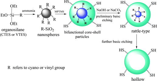 | ||
| Scheme 1 Schematic illustration for the preparation of thiol functionalized HSNSs based on the selective basic etching strategy. | ||
3.2 T-HMSNSs prepared from cyano-SiO2@thiol-SiO2
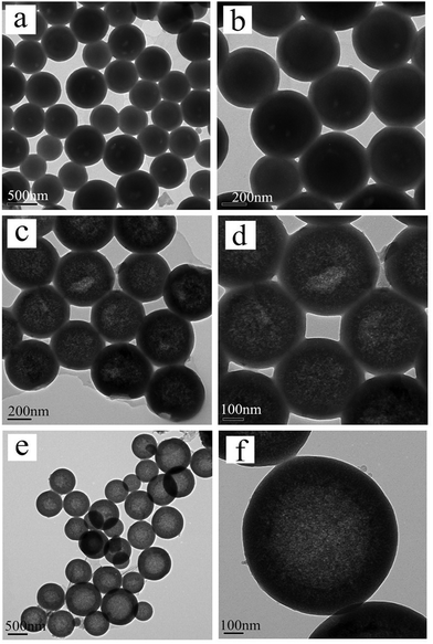
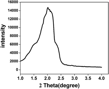
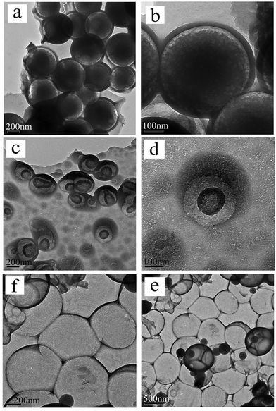
For cyano-SiO2@thiol-SiO2 composite particles, we chose Na2CO3 as an etching agent. After treating the composite particles in Na2CO3 solution (0.06 M) at 50 °C for 12 h, the typical TEM images of cyano-SiO2@thiol-SiO2 composite particles with about average of 50 nm thick shells and 350 nm size core are shown in Fig. 2a and b. The core of obtained samples was not destroyed seriously under this condition, and the particles still retained a perfect spherical structure and high dispersibility. Fig. 2c and d showed the TEM images of samples obtained by treating cyano-SiO2@thiol-SiO2 in 0.12 M Na2CO3 solution at 50 °C for 12 h. As mentioned before, in the cyano-SiO2@thiol-SiO2 particles, alkali resistance of the inner core was far weaker than the outer shell. Therefore, when further etched, the inner core of cyano-SiO2@thiol-SiO2 should be destroyed preferentially. From the TEM images shown in Fig. 2c and d, it could be observed that the core in cyano-SiO2@thiol-SiO2 became loose, and more mesopores were generated. The hollow structure was initially formed under this alkaline condition. And then, the concentration of the Na2CO3 solution was increased sequentially to convert cyano-SiO2@thiol-SiO2 into a complete hollow nanosphere. If other conditions were unchanged, when the concentration of Na2CO3 solution rose to 0.24 M, T-HMSNSs were finally fabricated as shown in Fig. 2e and f. More SEM images and corresponding TEM images are shown in Fig. S3 (ESI†).To further explore the microstructure of obtained T-HMSNSs, N2 adsorption–desorption measurements were carried out on the products corresponding to Fig. 2g and h. The N2 adsorption–desorption isotherms and pore size distributions are shown in Fig. 3, and specific surface area and pore volumes were 101.524 m2 g−1 and 0.32 cm3 g−1, respectively. These T-HMSNSs had relatively narrow pore size distributions in the range of 2–50 nm and an average diameter of 12 nm. The results of N2 adsorption–desorption measurements fully illustrated that the typical hollow mesoporous structure of the sample was fabricated. In this work, we only used organosilanes as precursors to prepare T-HMSNSs, and the high-density functional groups of T-HMSNSs may reduce their BET surface area in comparison with previous reports33,34 of hollow silica materials with larger BET surface area. The mesoporous structure of T-HMSNSs was further supported by X-ray diffraction (XRD) as shown in Fig. 4, and Fig. S5 (ESI†) showed the pore surface area. To the best of our knowledge, sSiO2 solid nanospheres do not diffract at low angles, while the obtained T-HMSNSs exhibited a definite diffraction peak from 1.5° to 2.5°, which is an important of sign of the mesoporous structure.35
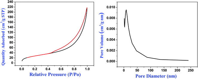 | ||
| Fig. 3 Brunauer–Emmett–Teller (BET) N2 adsorption–desorption curve (left) and pore distribution (right) of T-HMSNSs prepared from cyano-SiO2@thiol-SiO2. | ||
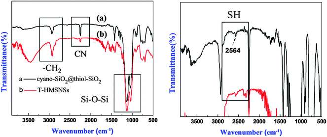
Fig. 5 exhibited the FTIR spectra of (a) cyano-SiO2@thiol-SiO2 composite particles and (b) T-HMSNSs, and the bands at 2250 cm−1 were related to stretching vibration of CN36 groups. MPTMS displayed characteristic –CH2 stretching bands at 2945 cm−1.37 The strong Si–O–Si stretching vibration band at 1097 cm−1 in s-SiO2 was split into two peaks (1028 and 1145 cm−1) and the bands at 2952 cm−1 were attributed to the symmetrical and asymmetrical stretching peak of –CH2,30 suggesting that organic groups have been introduced into silica nanospheres. In addition, the right picture is partial enlarged drawing of the left, in which the weak absorption peak of SH at 2564 cm−1 can be observed.38
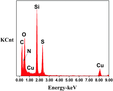
The results shown in Fig. 5 revealed that the obtained T-HMSNS samples contained Si, S, H, N, C, Cu and O (the Cu signals were attributed to the TEM grid of copper used for the EDS experiments). Among these elements, Si, S, C and H confirmed the presence of thiol-SiO2 synthesized from MPTMS, while N showed that cyano-SiO2 remained which was not etched completely. Table 1 presented element content analysis results of cyano-SiO2@thiol-SiO2 before and after etching. The lower level of N was observed after etching, while the content of S increased. The results further supported that cyano functionalized inner cores formed from CTES were etched preferentially.
| Sample | N (%) | C (%) | H (%) | S (%) |
|---|---|---|---|---|
| Cyano-SiO2@thiol-SiO2 | 9.68 | 32.25 | 4.238 | 6.337 |
| T-HMSNS | 3.21 | 29.28 | 4.584 | 14.902 |
3.3 T-HMSNSs prepared from vinyl-SiO2@thiol-SiO2 composite particles
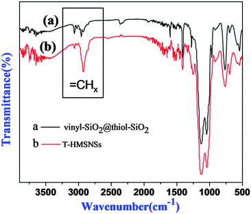
In order to explore the impact of different combinations of organosilanes, vinyl-SiO2@thiol-SiO2 composite particles were also etched under different conditions. As exhibited in Fig. 6, cyano-SiO2 showed weaker stability than vinyl-SiO2, therefore the stronger etching agent NaOH was chosen to etch vinyl-SiO2@thiol-SiO2 composite particles. Fig. 6 showed the representative TEM images of the samples prepared by etching at same temperature and time but at different concentrations of NaOH: (a and b) 0.04 M, (c and d) 0.08 M and (e and f) 0.16 M. When the concentration of NaOH was 0.04 M, typical rattle-type nanospheres were obtained (Fig. 6a and b), indicating that vinyl functionalized inner cores were destroyed initially. While the NaOH concentration was increased to 0.08 M, a novel void@SiO2@void@SiO2 structure was fabricated (Fig. 6c and d), and it was also found that particles began to blend and a layer of thin film was formed. This was because that the frame structure of composite particles became destabilized and collapsed partly under such strong alkaline conditions. Large-scale hollow nanospheres with a shell thickness of 20 nm were obtained when the NaOH concentration was increased to 0.16 M as shown in Fig. 6e and f. It could be observed that inner cores disappeared completely and the outer shell became thinner, suggesting that thiol-SiO2 was also destroyed to a certain extent. More SEM images and corresponding TEM images are shown in Fig. S4 (ESI†).For T-HMSNSs prepared from vinyl-SiO2@thiol-SiO2, the BET surface area and pore volume were only 27.9376 m2 g−1 and 0.0668 cm3 g−1, and the pore size distribution is centered at 1 nm (Fig. 7), which were lower than those of T-HMSNSs prepared from cyano-SiO2@thiol-SiO2. In addition, the pore surface area was also smaller (Fig. S5, ESI†). As seen from Fig. 1, the difference of alkali resistance between thiol-SiO2 and vinyl-SiO2 was not great. Thus when cores of vinyl-SiO2@thiol-SiO2 were etched, the outer shells were also partly eroded, and the nanospheres reunited seriously, which was responsible for the small surface area and pore volume. Fig. 8 exhibited the FTIR spectra of (a) vinyl-SiO2@thiol-SiO2 composite particles and (b) T-HMSNSs, and the stretching vibrations of ![[double bond, length as m-dash]](https://www.rsc.org/images/entities/char_e001.gif) CHx17 were observed, suggesting that there was still a few vinyl-SiO2 remained after etching (Fig. 9).
CHx17 were observed, suggesting that there was still a few vinyl-SiO2 remained after etching (Fig. 9).
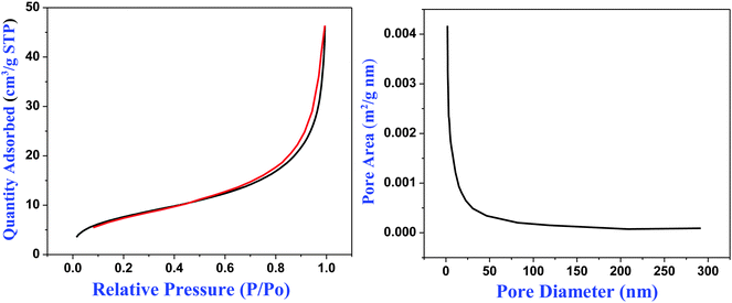 | ||
| Fig. 8 Brunauer–Emmett–Teller (BET) N2 adsorption–desorption curve (left) and pore distribution (right) of T-HMSNSs prepared from vinyl-SiO2@thiol-SiO2. | ||
4. Conclusion
In summary, an effective selective basic etching strategy has been developed for the synthesis of thiol functionalized hollow mesoporous silica nanospheres (T-HMSNSs) under facile conditions. In this strategy, the synthesis of core–shell silica composite particles with tailored resistance to base is a key for the formation of the hollow silica spheres. For cyano-SiO2@thiol-SiO2 and vinyl-SiO2@thiol-SiO2 core–shell particles, the thiol functionalized outer layer showed higher stability than the cyano and vinyl functionalized inner core. Hollow mesoporous nanospheres with high-density organic functional groups could be obtained by etching the core–shell particles under alkaline conditions. The morphology of products was regularly changed via manipulating the concentration of alkali in the etching process. By comparing the etching results of the two types of core–shell particles, it can be concluded that the great difference of alkali resistance between the core and the shell of composite particles is conducive to the fabrication of a hollow structure by an etching process. This facile strategy can be extended to prepare more nanomaterials with different structures and functional groups which contribute to various applications in drug/gene delivery, catalysis, and biomedicine.Acknowledgements
This work is financially supported by the Nature Science Foundation of Hubei Province (No. 2014CFB862), the State Key Laboratory of Natural and Biomimetic Drugs (No. K20140214) and the Fundamental Research Funds for the Central Universities (WUT: 2015IB002). We would also like to thank Ting ting Luo and Xiao qing Liu for their HRTEM analysis in the Materials Research and Test Center of WUT.References
- L. Han, J. Ruan, Y. Li, O. Terasaki and S. Che, Chem. Mater., 2007, 19, 2860 CrossRef CAS
.
- L. Feng, L. He, Y. Ma and Y. Wang, Mater. Chem. Phys., 2009, 116, 158 CrossRef CAS
.
- W. Xu, Q. Gao, Y. Xu, D. Wu, Y. Sun, W. Shen and F. Deng, J. Solid State Chem., 2008, 181, 2837 CrossRef CAS
.
- Y. Yang, X. Liu, X. Li, J. Zhao, S. Bai, J. Liu and Q. Yang, Angew. Chem., 2012, 124, 9298 CrossRef
.
- M. Nakamura and K. Ishimura, Langmuir, 2008, 24, 5099 CrossRef CAS PubMed
.
- J. Liu, S. Bai, H. Zhong, C. Li and Q. Yang, J. Phys. Chem. C, 2009, 114, 953 Search PubMed
.
- Y. Chen, C. Chu, Y. Zhou, Y. Ru, H. Chen, F. Chen, Q. He, Y. Zhang, L. Zhang and J. Shi, Small, 2011, 7, 2935 CrossRef CAS PubMed
.
- Y. Zhu, Y. Fang, L. Borchardt and S. Kaskel, Microporous Mesoporous Mater., 2011, 141, 199 CrossRef CAS
.
- J. Gao, X. Zhang, Y. Lu, S. Liu and J. Liu, Chem. – Eur. J., 2015, 21, 7403 CrossRef CAS PubMed
.
- J. Yu, W. Liu and H. Yu, Cryst. Growth Des., 2008, 8, 930 CAS
.
- T. S. Deng and F. Marlow, Chem. Mater., 2012, 24, 536 CrossRef CAS
.
- J. F. Chen, H. M. Ding, J. X. Wang and L. Shao, Biomaterials, 2004, 25, 723 CrossRef CAS PubMed
.
- G. Qi, Y. Wang, L. Estevez, A. K. Switzer, X. Duan, X. Yang and E. P. Giannelis, Chem. Mater., 2010, 22, 2693 CrossRef CAS
.
- Y. Yamada, M. Mizutani, T. Nakamura and K. Yano, Chem. Mater., 2010, 22, 1695 CrossRef CAS
.
- J. Wang, Q. Xiao, H. Zhou, P. Sun, Z. Yuan, B. Li, D. Ding, A. C. Shi and T. Chen, Adv. Mater., 2006, 18, 3284 CrossRef CAS
.
- J. Liu, S. B. Hartono, Y. G. Jin, Z. Li, G. Q. Lu and S. Z. Qiao, J. Mater. Chem., 2010, 20, 4595 RSC
.
- J. Li, L. Chen, X. Li, C. Zhang and Y. Jiang, New J. Chem., 2015, 39, 287 RSC
.
- M. Yu, H. Wang, X. Zhou, P. Yuan and C. Yu, J. Am. Chem. Soc., 2007, 129, 14576 CrossRef CAS PubMed
.
- J. G. Wang, F. Li, H. J. Zhou, P. C. Sun, D. T. Ding and T. H. Chen, Chem. Mater., 2009, 21, 612 CrossRef CAS
.
- T. Zhang, Q. Zhang, J. Ge, J. Goebl, M. Sun, Y. Yan and Y. Yin, J. Phys. Chem. C, 2009, 113, 3168 CAS
.
- Q. Zhang, W. S. Wang, J. Goebl and Y. D. Yin, Nano Today, 2009, 4, 494 CrossRef CAS
.
- Y. Hu, Q. Zhang, J. Goebl, T. R. Zhang and Y. D. Yin, Phys. Chem. Chem. Phys., 2010, 12, 11836 RSC
.
- Q. Zhang, J. Ge, J. Goebl, Y. Hu, Z. Lu and Y. Yin, Nano Res., 2010, 2, 583 CrossRef
.
- Y. Chen, H. Chen, D. Zeng, Y. Tian, F. Chen, J. Feng and J. Shi, ACS Nano, 2010, 4, 6001 CrossRef CAS PubMed
.
- M. Wu, Y. Chen, L. Zhang, X. Li, X. Cai, Y. Du and J. Shi, J. Mater. Chem. B, 2015, 3, 766 RSC
.
- Y. Chen, C. Chu, Y. Zhou, Y. Ru, H. Chen, F. Chen and J. Shi, Small, 2011, 7, 2935 CrossRef CAS PubMed
.
- K. Zhang, H. Chen, Y. Zheng, Y. Chen, M. Ma, X. Wang, L. Wang, D. Zeng and J. Shi, J. Mater. Chem., 2012, 22, 12553 RSC
.
- D. Chen, L. Li, F. Tang and S. Qi, Adv. Mater., 2009, 21, 3804 CrossRef CAS
.
- N. Hao, K. W. Jayawardana, X. Chen and M. Yan, ACS Appl. Mater. Interfaces, 2015, 7, 1040 CAS
.
- Z. Meng, C. Xue, Q. Zhang, X. Yu, K. Xi and X. Jia, Langmuir, 2009, 25, 7879 CrossRef CAS PubMed
.
- C. Oh, S. B. Shim, Y. G. Lee and S. G. Oh, Mater. Res. Bull., 2011, 46, 2064 CrossRef CAS
.
- T. S. Deng, Q. F. Zhang, J. Y. Zhang, X. Shen, K. T. Zhu and J. L. Wu, J. Colloid Interface Sci., 2009, 329, 292 CrossRef CAS PubMed
.
- S. K. Das, M. K. Bhunia, D. Chakraborty, A. R. Khuda-Bukhsh and A. Bhaumik, Chem. Commun., 2012, 48, 2891 RSC
.
- M. Sasidharan, H. Zenibana, M. Nandi, A. Bhaumik and K. Nakashima, Dalton Trans., 2013, 42, 13381 RSC
.
- X. Fang, C. Chen, Z. Liu, P. Liu and N. Zheng, Nanoscale, 2011, 3, 1632 RSC
.
- Y. C. Pan, H. Y. Wu, L. P. Lee, G. L. Jheng, G. T. K. Fey and H. M. Kao, Microporous Mesoporous Mater., 2009, 123, 78 CrossRef CAS
.
- Y. Fang, Y. Chen, X. Li, X. Zhou, J. Li, W. Tang, J. Huang, J. Jin and J. Ma, J. Mol. Catal. A: Chem., 2014, 392, 16 CrossRef CAS
.
- R. Rostamian, M. Najafi and A. A. Rafati, Chem. Eng. J., 2011, 171, 1004 CrossRef CAS
.
Footnote |
| † Electronic supplementary information (ESI) available. See DOI: 10.1039/c5nj02906f |
| This journal is © The Royal Society of Chemistry and the Centre National de la Recherche Scientifique 2016 |


