MnO2 nanomaterials for flexible supercapacitors: performance enhancement via intrinsic and extrinsic modification
Teng
Zhai
ab,
Xihong
Lu
a,
Fuxin
Wang
a,
Hui
Xia
*b and
Yexiang
Tong
*a
aKLGHEI of Environment and Energy Chemistry, MOE of the Key Laboratory of Bioinorganic and Synthetic Chemistry, School of Chemistry and Chemical Engineering, Sun Yat-Sen University, Guangzhou 510275, People's Republic of China. E-mail: chedhx@mail.sysu.edu.cn
bHerbert Gleiter Institute of Nanoscience, Nanjing University of Science and Technology, Nanjing, 210094, China. E-mail: xiahui@njust.edu.cn
First published on 25th September 2015
Abstract
Increasing power and energy demands for next-generation portable and flexible electronics have raised critical requirements (flexibility, stretch-ability, environmental friendliness, lightweight, etc.) for the energy storage devices. Flexible supercapacitors (SCs), as one of the most promising next-generation energy storage devices, have stimulated intensive interest owing to their outstanding features including small size, low weight, ease of handling, excellent reliability, and high power density. Manganese oxide (MnO2), has attracted much interest in the development of flexible SCs with high electrochemical performance. Yet, the poor electronic and ionic transport in MnO2 electrodes still limits its promotion in practical applications. This review aims to describe the recent progress in the application of MnO2 materials in the development of flexible SCs and summarizes the intrinsic modification of MnO2via crystallinity, crystal structure, and oxygen vacancy introduction and the extrinsic modification of MnO2via non-three-dimensional (3D) and 3D flexible conductive scaffolds for high performance flexible SCs. Moreover, we also discuss briefly on the current challenges, future directions, and opportunities for the development of high-performance MnO2 based flexible SCs.
1. Introduction
There has been an increasing demand for fossil fuel originated energy in the past thirty years. However, it may not be possible to provide sufficient energy as the world population continues to grow and the limited amount of fossil fuels has begun to diminish.1 Sustainable energy sources including solar energy, wind, and tidal energy have emerged as promising candidates to replace the conventional fossil fuel.2 Since the supply is intermittent and strongly dependent on the natural environment, the development of these sustainable energy sources has been greatly limited by their storage. Moreover, the highly efficient, low cost energy storage devices for these kinds of intermittent renewable energies are still one of the greatest challenges. Supercapacitors (SCs), also known as electrochemical capacitors (ECs), have been recognized for more than fifty years and considered as one of the energy storage systems with the most potential.3–5 With the rapid growth of electronics, there is increasing demand for flexible or space-saving electronic devices such as wearable electronics, mobile phones, and flexible displays.6,7 To catch up with the rapid growth of the demand for portable flexible electronics, it is essential to develop high performance and reliable flexible energy storage devices. In this regard, flexible supercapacitors with high energy density, high power density (high-rate current output/input), and high cycling stability must facilitate practical use of portable flexible electronics. However, it remains a major concern to achieve improved electrochemical performance and ultrahigh flexibility simultaneously.According to the charge storage mechanism of electrode materials in SCs, they can be generally divided into two categories: electrical double-layer capacitors (EDLCs) and pseudocapacitors.8Fig. 1 compares the specific capacitances of various types of electrode materials based on these two mechanisms for SCs. The EDLC mechanism based carbon materials store the electrical charge via a physical charge separation process, which is strongly dependent on the pore size distribution and high surface area of the carbon materials. In this regard, highly conductive and chemically stable carbon materials with large surface area, such as graphene,9–11 carbon nanotubes (CNTs),12,13 and activated carbon,14 have been widely used as electrode materials for EDLCs and achieve specific capacitances of around 50–350 F g−1. Due to their conductive electrochemical properties and physical storage process, carbon material based EDLCs can achieve high power (>10 kW kg−1) and long term cycle stability (>105 cycles). However, they suffer from low capacitance derived low energy density (1–10 W h kg−1). In contrast, conducting polymer or metal oxide based pseudocapacitors can deliver much higher specific capacitance due to the fact that charges are stored via fast and reversible faradic reactions at the surface and bulk of the electrode materials. This will certainly lead to higher energy density (20–50 W h kg−1) in comparison with EDLCs. It should be noted that, due to the slow diffusion of ions within the bulk of the electrode and a relatively slower charge storage mechanism compared with simple adsorption/desorption, the pseudocapacitors usually possess a relatively lower power density (0.5–2 kW kg−1). In addition, they often begin to degrade under less than one or two thousand cycles due to changes in their physical structure and dissolution problems. Therefore, significant efforts have been devoted in the past years to the concerns of pseudocapacitors.
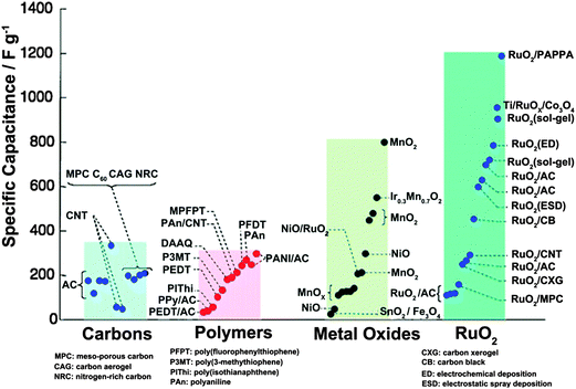 | ||
| Fig. 1 Reported specific capacitances for electrode materials. Reprinted from ref. 15 with the permission from interface, Copyright 2008 – The Electrochemical Society. | ||
Among various pseudocapacitive materials, manganese oxide (MnO2) is characterized by a low-cost (compared with highly expensive RuO2) material with a high theoretical capacitance (∼1370 F g−1) in a wider working potential window (∼0.8 to 1 V vs. Ag/AgCl in aqueous electrolytes). Over the past decades, MnO2 has become one of the most widely investigated pseudocapacitive electrode materials. Latest developments in MnO2 based supercapacitors have been recently reviewed.4,16 However, the practical capacitance is around 200–600 F g−1 at a mass loading of less than 1 mg cm−2,17 so the full potential of MnO2 for SCs still needs to be further exploited. Intensive explorations have shown that one major issue crucial for MnO2 based SCs to achieve fascinating capacitive performance is fast electron and ion transportation in materials or at interface. To solve this problem, considerable efforts have been devoted to the crystallinity,18,19 crystal structure,20–24 morphology, nano or micro structural design,25–31 and vacancy introduction32–36 of MnO2 to pursue high-performance MnO2 based SCs. Fortunately, progress has been made within recent years. Herein, we review the recent progress in the application of MnO2 materials in the development of flexible supercapacitors and discuss briefly the current challenges, future directions and opportunities for the development of high-performance MnO2 based flexible SCs.
2. Evaluation of electrodes and SCs
Cyclic voltammetry (CV) and galvanostatic charge/discharge (GCD) measurements are two main techniques to evaluate the electrochemical properties of SCs such as specific or areal/volumetric capacitance, rate capability, cycling stability, etc. Generally, the specific or areal/volumetric capacitance can be calculated viaeqn (1) and (2) as follows:CV curves:
 | (1) |
GCD curves:
 | (2) |
The average gravimetric power density (Ps) and energy density (Es) were calculated by using the following eqn (3) and (4):
 | (3) |
 | (4) |
The corresponding volumetric average power density and volumetric energy density can be obtained by replacing Cs with Cv.
Large values of specific capacitance are always favoured for pursuing the corresponding high energy densities. It should be noted that the mass loading and charge/discharge rate are crucial for the evaluation of specific capacitance. High specific capacitance at higher mass loading and charge/discharge rate, which means high areal capacitance and output power, is more meaningful for SCs at a practical device level. With respect to high energy density, the unquestioning pursuit of a large voltage window is also meaningless. High coulombic efficiency and highly stable and reversible reactions in the selected voltage window are key parameters for evaluations.
3. High-performance MnO2 based flexible electrodes
Since the first report about the supercapacitor behavior of MnO2 by Lee and Goodenough in 1999,37 it has attracted intensive attention and is considered as one of the most promising active materials for SCs due to its high theoretical capacitance (∼1300 F g−1), low cost, environmentally friendly features.38,39 The high capacitance of MnO2 mainly originates from its pseudocapacitance, which can be attributed to the faradic reactions occurring at the surface and subsurface in the bulk of the MnO2 phase. Previous reports40,41 have indicated that the adsorption/desorption (at surface) or intercalation/deintercalation (at subsurface) of protons and cations are involved in the charge storage process, as well as the transition between Mn(III) and Mn(IV):| MnIII(x+y)MnIV1−(x+y)OOCxHy ↔ MnIVO2 + xC+ + yH+ + (x + y)e− | (5) |
Fig. 2a presents the schematic of cyclic voltammetry (CV) for a single MnO2 electrode in a mild aqueous electrolyte (0.1 M K2SO4).42 The dotted lines highlight the successive multiple surface redox reactions occurring during the charge/discharge process in the potential window 0–1 V vs. Ag/AgCl. The oxidation from Mn(III) to Mn(IV) accounts for the upper (red) part, while the reverse reduction relates to the lower (blue) part. Clearly, the fast, reversible, and successive multiple reactions take place throughout the potential range 0–1 V, leading to a well-defined rectangular shaped CV curve (analogous to EDLC behavior). It has been reported that the reversible redox transition of Mn(II)/Mn(III) may also be involved in the charge storage process.4,43 Very recently, Yu-Ting Weng et al. investigated in detail the transitions between Mn(III)/Mn(II), Mn(IV)/Mn(III) within the electrode potential window −1–1 V vs. Ag/AgCl.43Fig. 2b shows the schematic expression of various charge-storage mechanisms for MnO2 as a function of potential. At a low scan rate of 2 mV s−1, the battery behavior of transition between Mn(II)/Mn(III) accounts for ∼1/2 of the charge storage. However, the attribution of Mn(II)/Mn(III) decreases sharply when the scan rate increases to 100 mV s−1, indicating that achieving high ionic and electronic conductivities is the major issue for MnO2 to achieve fascinating capacitive performance. Unfortunately, the MnO2 always suffers from poor electronic (10−6 to 10−3 S cm−1) and ionic conductivities, resulting in a poor specific capacitance of around 300–400 F g−1 (∼1 mg cm−2), which is far from its theoretical capacitance of ∼1300 F g−1.44,45
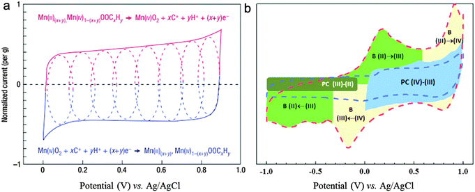 | ||
| Fig. 2 (a) Schematic of cyclic voltammetry for a MnO2 electrode in a mild aqueous electrolyte (0.1 M K2SO4). The dotted lines highlight the successive multiple surface redox reactions occurring during the charge/discharge process: oxidation from Mn(III) to Mn(IV) accounts for the upper (red) part, while the reverse reduction relates to the lower (blue) part. Adapted with permission from ref. 42, Copyright Nature Publishing Group 2008. (b) A schematic expression of various charge-storage mechanisms as a function of potential; B: battery behavior; PC: pseudocapacitance; (IV), (III), and (II): Mn ions having valences of 4, 3, and 2, respectively. Adapted with permission from ref. 43, Copyright Wiley-VCH 2015. | ||
As reported in the literature in recent years, both the intrinsic modification (crystal structure and crystallinity, microstructural construction, and valence introduction) and extrinsic modification (non-3D and 3D carbon and metal oxide based composites) were used to synthesize MnO2 with improved ionic and electronic properties for high performance flexible SCs.
3.1 Intrinsically modified MnO2 electrodes for flexible SCs
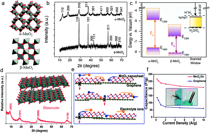 | ||
| Fig. 3 (a) Schematic crystal structure of α-MnO2 and β-MnO2. (b) XRD patterns of α-MnO2 and β-MnO2. Reprinted from ref. 104 with permission from Copyright© 2002, American Chemical Society. (c) Absolute band edge energies of α-MnO2 (left) and β-MnO2 (center) and the electrochemical scanned potential window (SPW) for MnO2 in aqueous electrolyte at pH = 7.4 (right). Reprinted from ref. 41 with permission from Copyright© 2015, American Chemical Society. (d) The XRD pattern of the bulk birnessite. The inset is a schematic crystal structure of δ-MnO2 (birnessite). (e) A schematic description of the 2D planar ion transport favored within the 2D δ-MnO2 /graphene hybrid structures. (f) Specific capacitance of planar supercapacitors based on the 2D δ-MnO2/graphene hybrid at different scan rates (from 0.5–10 A g−1). The insets show the different bending states (folded and rolled) of planar supercapacitors. Reprinted from ref. 22 with permission from Copyright© 2013, American Chemical Society. | ||
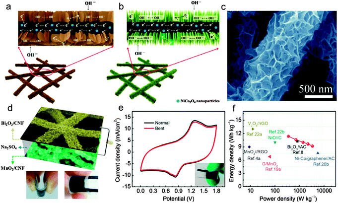 | ||
| Fig. 4 Illustration of the electron and ion transport pathways in the (a) NiCo2O4-doped carbon nanofiber (NCCNF)@MnO2 nanosheet hybrid membrane and (b) NCCNF@MnO2 nanorod hybrid membrane. Reprinted from ref. 28 with permission from Copyright© 2015, American Chemical Society. (c) The SEM image of MnO2 nanoflowers on carbon nanofibers. (d) A schematic illustration of the as-assembled MnO2 nanoflower based flexible SCs. The digital images present its flexibility. (e) CV curves (collected at 200 mV s−1) of the as-assembled flexible SCs under flat and bending states. (f) Ragone plots of the MnO2 nanoflower based device. The values reported for other ASCs are added for comparison. Adapted with permission from ref. 25, Copyright Wiley-VCH 2015. | ||
Besides the nano-structured construction of MnO2 materials, the micro-structured construction of MnO2 electrodes is another effective method for MnO2 to achieve fast ion transport during the charge storage process. The fiber or wire based SCs have been considered to possess distinct advantages over the planar counterparts in the development of reconfigurable, lightweight, and portable electronics.30,61–63 Significantly, a wire-shaped device can be co-woven using the well-developed textile technology.64 Xu et al.31 fabricated an all-solid-state fiber-shaped ASC via wrapping a conducting carbon paper on a MnO2 nanoflower coated nanoporous gold wire. The MnO2 nanoflower coated nanoporous gold wire electrode exhibits an outstanding capacitance retention of ∼88.2% as the current density increases from 0.5 to 8 mA cm−2, indicating its high electronic and ionic conductivities. Fig. 5a shows the CV curves of the as fabricated fiber-shaped ASC device under different bending states collected at a scan rate of 100 mV s−1. Negligible electrochemical performance changes can be observed for the fiber-shaped device under different bending states (0°, 90°, and 180°). Moreover, the devices are woven into textile structures to show the great potential for future flexible electronic devices (Fig. 5b).
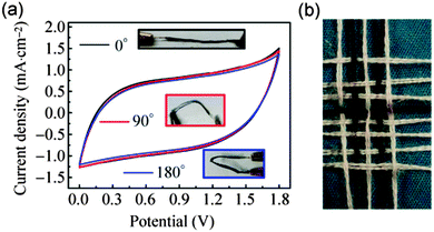 | ||
| Fig. 5 (a) CV curves of the fiber-shaped ASC device under different bending states collected at a scan rate of 100 mV s−1. The insets are the photo images of the device under different bending states (0°, 90°, 180°). (b) The photograph of the fiber-shaped device integrated with conventional cotton yarns. Reprinted from ref. 31 with the permission from the Tsinghua University Press and Springer-Verlag Berlin Heidelberg 2014. | ||
Aiming at applications in wearable electronics, the stretch ability has become an important factor for flexible fiber shaped SCs. However, the stretchable fiber shaped SCs are still rarely reported or still suffer from low capacitance, low working potential (usually 0.8 V).65–67 Until very recently, Xu and his co-workers30 assembled a stretchable fiber-shaped ASC constituted of an MnO2/CNT hybrid fiber positive electrode, a CNT fiber negative electrode and a KOH–PVA electrolyte (Fig. 6a). By taking advantage of the stable working potential of the MnO2/CNT fiber positive electrode (0–0.5 V vs. Ag/AgCl) and CNT fiber negative electrode (−0.4 to −1 V vs. Ag/AgCl), the voltage window of the as assembled ASC device was extended to 1.5 V. A high specific capacitance of ∼157.53 μF cm−1 at 50 mV s−1 was delivered in an extended voltage window of 0–1.5 V. Remarkably, a cyclic tensile strain of up to 100% presents negligible effects on the electrochemical performance of the stretchable ASC device. As shown in Fig. 6b, the redox peaks are still well maintained at different tensile strains (0%, 40%, 70%, and 100%) and even after 20 mechanical stretching–releasing cycles (MSRCs), indicating the negligible effects of stretch states to the capacitive performance. The minor capacitance change for the stretched ASC device at various scan rates again confirms its high stretch ability (Fig. 6c). Moreover, the specific capacitance still retains more than 99% after 10![[thin space (1/6-em)]](https://www.rsc.org/images/entities/char_2009.gif) 000 galvanostatic charge/discharge cycles, indicating the long cycling stability.
000 galvanostatic charge/discharge cycles, indicating the long cycling stability.
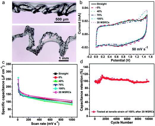 | ||
| Fig. 6 (a) Photo images of the as assembled stretchable ASC device. (b) CV curves at different stretching states. (c) Specific capacitance variations with scan rates. (d) Cycling performance of the asymmetric supercapacitor at a current density of 2.8 mA cm−2 after 20 MSRCs. Reprinted from ref. 30 with permission from the Copyright© 2015, American Chemical Society. | ||
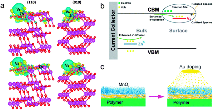 | ||
| Fig. 7 (a) The charge density difference of (010) and (110) surfaces of Zn-doped ramsdellite-MnO2 with the oxygen vacancies of site I. The blue and yellow areas highlight the electron loss and gain, respectively. (b) A schematic illustration of the effects on the MnO2 materials from Zn2+ doping. Reprinted from ref. 75 with the permission from Royal Society of Chemistry 2015. (c) A sketch of the fabrication process of the Au-doped MnO2 electrodes. Reprinted from ref. 77 with the permission from 2013 Wiley-VCH Verlag GmbH & Co. KGaA, Weinheim. | ||
Annealing in de-oxygen or reducing in ambient atmosphere is the second effective approach for the introduction of oxygen vacancies into MnO2.36,70 Zhai et al. demonstrated an effective strategy, annealed MnO2 in hydrogen atmosphere (Fig. 8a), to intrinsically improve the conductivity and capacitive performance of MnO2 by inducing oxygen vacancies.36Fig. 8b shows the areal capacitance and surface Mn oxidation state of hydrogenated MnO2 (H-MnO2) as a function of the hydrogenated temperature. It could be observed that the H-MnO2 samples exhibit a higher areal capacitance in comparison with the untreated MnO2 sample. Moreover, H-MnO2 hydrogenated at 250 °C with moderate oxygen vacancies exhibits the highest areal capacitance of 0.22 F cm−2 (449 F g−1) at 0.75 mA cm−2. Significantly, a solid-state ASC based on the H-MnO2 and reduced graphene oxide was assembled and exhibited a higher energy density and power density (0.25 mW h cm−3 at 1.01 W cm−3) over other reported SC devices (Fig. 8c). Finally, to test the feasibility of the H-MnO2//RGO ASC device as an energy storage device in wearable electronics, the as-fabricated flexible ASC was knitted into laboratory clothing as a demonstration (Fig. 8d).
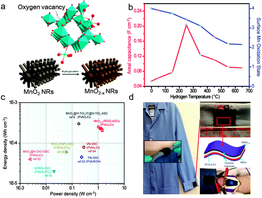 | ||
| Fig. 8 (a) Schematic diagram illustrating the growth process for preparing hydrogenated MnO2 (H-MnO2) NRs on carbon cloth substrate. (b) Areal capacitance and surface Mn oxidation state of H-MnO2 as a function of hydrogenated temperature. (c) Ragone plots of the H-MnO2//RGO ASC device measured in the gel electrolyte. The values reported for other SC devices are added for comparison. (d) Photo images of the cloth model and the zoom-in image of wearable ASCs sewing on the cloth model. Reproduced from the ref. 36 with the permission from 2014 Elsevier Ltd. | ||
3.2 Extrinsically modified MnO2 electrodes for flexible SCs
In addition to intrinsic modification of MnO2, the extrinsic combination of MnO2 with highly conductive materials, such as carbon based materials,78–82 metal oxides or conductive polymer based materials,83–85 has also been investigated extensively for flexible SCs. As the flexible SCs raised critical requirements for these highly conductive supports, the supports for MnO2 are required to have high mechanical integrity upon bending or folding and lightweight property and excellent electrochemical properties.86 Herein, we review in detail the MnO2 materials grown on non-3D and 3D conductive and flexible supports for flexible SCs.| Active materials | Conductive scaffold | Capacitance | Mass loading | Flexibility (capacitance retention %) | Energy density retention of SCs | Energy density (E) | Power density (P) | Cycle stability | Ref. |
|---|---|---|---|---|---|---|---|---|---|
| MnO2 | Graphene/CNT paper | 486.6 F g−1 at 2 mV s−1 | — | Negligible variation of electrical conductivity (1000 bending cycles) | ∼40% (power density form 150 to 2250 W kg−1) | 24.8 W h kg−1 | ∼150 W kg−1 | — | 80 |
| MnO2 | 3D hollow structured graphene | ∼280 F g−1 at 2 mV s−1 | 0.42 mg cm−2 | 92% (200 bending cycles) | ∼55% (P form 62 to 2500 W kg−1) | 6.8 W h kg−1 | 62 W kg−1 | 81.2% after 5000 cycles | 78 |
| MnO2 | 3D graphene/CNT | 343.1 F g−1 at 2 mV s−1 | 0.21 mg cm−2 | — | ∼56.8% (P form 170.5 to 22727 W kg−1) | 33.71 W h kg−1 | 170.5 W kg−1 | 95.3% after 1000 cycles | 90 |
| MnO2 | Graphene foam | 422.5 F g−1 at 1 A g−1 | — | ∼97% after bending 180° for 100 times. | ∼57.2% (P form 453.6 to 9188.1 W kg−1) | 31.8 W h kg−1 | 453.6 W kg−1 | 84.4% after 10![[thin space (1/6-em)]](https://www.rsc.org/images/entities/char_2009.gif) 000 cycles 000 cycles |
82 |
| MnO2 | H-TiO2 nanowires@ carbon cloth | 449.6 F g−1 at 10 mV s−1 | 0.23 mg cm−2 | Negligible variation at twisted and bending states | ∼56.7% (P form 35![[thin space (1/6-em)]](https://www.rsc.org/images/entities/char_2009.gif) 000 to 45 000 to 45![[thin space (1/6-em)]](https://www.rsc.org/images/entities/char_2009.gif) 000 W kg−1) 000 W kg−1) |
0.30 mW h cm−3 (59 W h kg−1) | 0.23 W cm−3 (45 kW kg−1) | 91.2% after 5000 cycles | 85 |
| MnO2 nanorod | Graphene film | 209 F g−1 at 1 mV s | — | ∼97.2% at the bent states | ∼24% (P form 101.5 to 24![[thin space (1/6-em)]](https://www.rsc.org/images/entities/char_2009.gif) 500 W kg−1) 500 W kg−1) |
50.8 W h kg−1 | 101.5 W kg−1 | 81% after 1000 cycles | 87 |
| MnO2 | Few walled CNT paper | 203 F g−1 at 2 mV s−1 | — | — | 89% (P form 130 to 7800 W kg−1) | 23.9 W h kg−1 | 7.8 kW kg−1 | 95% after 2000 cycles | 88 |
| Ppy/MnO2 | Carbon fiber | — | — | 99.76% when it was rolled up | ∼26% (P form 0.05 to 2 W cm−3) | 6.16 mW h cm−3 | 0.05 W cm−3 | 86.7% after 1000 cycles | 84 |
| MnO2 | CNF paper | 525 mF cm−2 (110 F g−1) at 3 mA cm2 | 3.1 mg cm−2 | Yes | 80.5% (P form 352.6 to 3370 W kg−1) | 43.4 μW h cm−2 (11.3 W h kg−1) | 1.35 mW cm−2 (352.6 W kg−1) | 85% after 4000 cycles | 25 |
| CuCo2O4@MnO2 nanowire | Carbon fabrics | 327 F g−1 at 1.25 A g−1 | 0.5 mg cm−2 | No significant deviations at 0, 30, 60, 90° | 70% (P form 0.4745 to 3120 mW cm−2) | 94.3 W h cm−2 | 0.4757 mW cm−2 | Long-term cycling life over 3000 cycles in different bent states | 89 |
| MnO2 | Polyethylene terephthalate | 4.72 mF cm−2 at 5 μA cm−2 | — | SC No obvious change bent at 0, 90° | — | — | — | 85.5% capacitance retention after 500 cycles | 91 |
| Ppy/MnO2 | CNT textile | 461.0 F g−1 at 0.2 A g−1 | — | SC 96.2% of initial value after 750![[thin space (1/6-em)]](https://www.rsc.org/images/entities/char_2009.gif) 000 bending cycles 000 bending cycles |
— | 31.1 W h kg−1 | 22.1 kW kg−1 | 93.8% capacitance retention after 10![[thin space (1/6-em)]](https://www.rsc.org/images/entities/char_2009.gif) 000 cycles 000 cycles |
92 |
| MnO2 | Stainless steel mesh | 667 F g−1 at 5 mV s−1 | — | — | — | 93 |
Qiu and his co-workers91 recently developed for the first time a novel Au@MnO2 core–shell nanomesh structure on a flexible polymeric substrate. Fig. 9a shows the illustration of the fabrication of flexible SCs based on the flexible Au@MnO2 nanomesh electrode. The average diameter of the applied polystyrene (PS) particle was around 700 nm and the as prepared Au nanomesh film with a thickness of 50 nm achieved a sheet resistance of 13–18 Ω sq−1, indicating a higher surface area (compared with platform supports) and good conductivities. Moreover, a flexible SC (Fig. 9c) based on the Au@MnO2 nanomesh electrode was assembled to explore the advantages of this novel design. A stable coulombic efficiency of greater than 95% over 1000 cycles was obtained at flat and bent states, indicating the stable Au nanomesh supports and strong coupling between the Au nanomesh and MnO2 nanosheets. However, the surface area of Au nanomesh flexible supports still cannot be compared with the one-dimensional (1D) nanostructured supports. Furthermore, the use of Au may hinder the wide range of applications of the Au nanomesh. Lu et al.85 developed a high-performance and flexible solid-state ASC device based on 1D core–shell nanowire (NW) electrodes (Fig. 10a). The hydrogen-treated TiO2 (denoted as H-TiO2) NWs were adopted as the core (conducting scaffold) to support electrochemically active MnO2. Fig. 10b presents the CV curves collected for H-TiO2, MnO2, TiO2@MnO2 and H-TiO2@MnO2 electrodes at a scan rate of 100 mV s−1. Obviously, the H-TiO2@MnO2 electrode exhibits a substantially higher current density than the values obtained for the MnO2 and TiO2@MnO2 electrodes, which can be attributed to the increased surface area through the H-TiO2 nanostructured supports and the enhanced charge transport for TiO2 after hydrogenation. As the scan rate increased from 10 to 200 mV s−1, the H-TiO2@MnO2 electrode retained 54.6% of its capacitance, which is also substantially higher than that of the MnO2 (29.4%) and TiO2@MnO2 (43.4%) electrodes, again confirming the enhanced charge transport during the charge/discharge process. Moreover, the electrode materials directly grown on carbon cloth endow the ASC device with outstanding flexibility (Fig. 10d). The as assembled flexible ASC device delivered a maximum energy density of 0.30 mW h cm−3 (59 W h kg−1) (Fig. 10e), which is higher than most of the reported SSCs.11,79,94,95
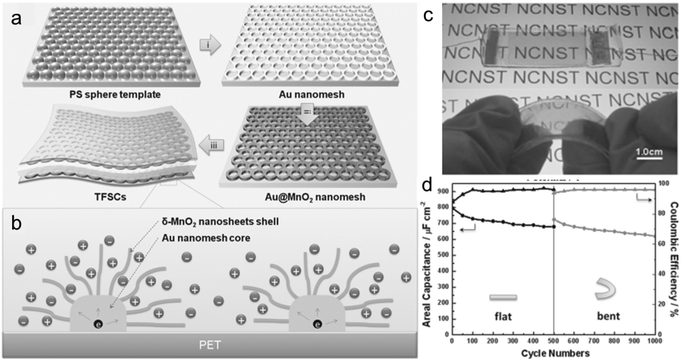 | ||
| Fig. 9 (a) Schematic illustration for the fabrication of flexible SCs based on the Au@MnO2 nanomesh. (b) A schematic diagram of ion diffusion pathways and charge transport channels of the Au@MnO2 nanomesh electrode. (c) Photo images of the Au@MnO2 nanomesh electrode based SCs sealed in a PDMS film, flat and bent. (d) Cyclic stability and coulombic efficiency of the device at flat and bending states. Reprinted from ref. 91 with the permission from 2014 Wiley-VCH Verlag GmbH & Co. KGaA, Weinheim. | ||
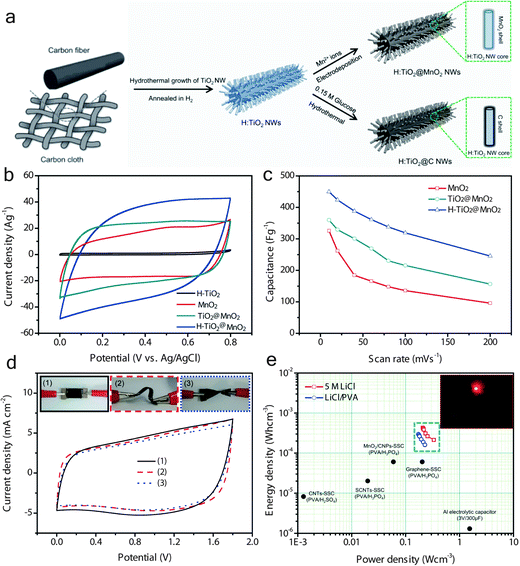 | ||
| Fig. 10 (a) Schematic diagram illustrating the growth processes for H-TiO2@MnO2 and H-TiO2@C core–shell NWs on a carbon cloth substrate. (b) CV curves collected for H-TiO2, MnO2, TiO2@MnO2 and H-TiO2@MnO2 electrodes at a scan rate of 100 mV s−1. (c) Specific capacitance of these electrodes as a function of the scan rate. (d) CV curves collected at a scan rate of 100 mV s−1 for the ASC device under flat, bent, and twisted conditions. The insets are the device pictures under test conditions. (e) Ragone plots of the ASC devices measured in aqueous and gel electrolytes. The values reported for other SC devices are added for comparison. Reprinted from ref. 85 with the permission from 2013 Wiley-VCH Verlag GmbH & Co. KGaA, Weinheim. | ||
Similar to other transition metal oxides, MnO2 also suffers from the delamination problems caused by the large volume changes during charge/discharge cycles, and hence a decrease in electrochemical stability.96,97 To prevent the delamination of nanostructured MnO2 electrodes, researchers have tried to coat a thin conductive layer on the top of MnO2.92,98 Yun et al.92 used the polypyrrole (Ppy) conductive polymer to coat on the top of MnO2 nanoparticles to prevent delamination (Fig. 11a). With the protected conductive polymer layer, the Ppy–MnO2/CNT electrode achieved improved cycling stability, with 93.8% normalized capacitance after 10![[thin space (1/6-em)]](https://www.rsc.org/images/entities/char_2009.gif) 000 cycles (Fig. 11b), which is higher than that of the MnO2/CNT electrode. Significantly, the Ppy–MnO2/CNT based SCs exhibited excellent flexibility (Fig. 11c). As shown in Fig. 11d, the Ppy–MnO2/CNT based SCs still well retained the almost original capacitive performance even after 750
000 cycles (Fig. 11b), which is higher than that of the MnO2/CNT electrode. Significantly, the Ppy–MnO2/CNT based SCs exhibited excellent flexibility (Fig. 11c). As shown in Fig. 11d, the Ppy–MnO2/CNT based SCs still well retained the almost original capacitive performance even after 750![[thin space (1/6-em)]](https://www.rsc.org/images/entities/char_2009.gif) 000 bending cycles, with capacity retention of 98.9, 98.4, and 96.2% of initial value after 250
000 bending cycles, with capacity retention of 98.9, 98.4, and 96.2% of initial value after 250![[thin space (1/6-em)]](https://www.rsc.org/images/entities/char_2009.gif) 000, 500
000, 500![[thin space (1/6-em)]](https://www.rsc.org/images/entities/char_2009.gif) 000, and 750
000, and 750![[thin space (1/6-em)]](https://www.rsc.org/images/entities/char_2009.gif) 000 bending cycles, respectively.
000 bending cycles, respectively.
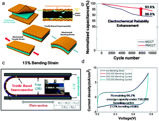 | ||
Fig. 11 (a) Schematic illustration of a Ppy–MnO2-coated textile SC. (b) Cycling stability of the Ppy–MnO2-coated textile electrode. (c) A schematic of the bending test performed on the Ppy–MnO2-coated textile SC. (d) CV curves of the supercapacitor under 13% bending strain collected at 0, 250![[thin space (1/6-em)]](https://www.rsc.org/images/entities/char_2009.gif) 000, 500 000, 500![[thin space (1/6-em)]](https://www.rsc.org/images/entities/char_2009.gif) 000, and 750 000, and 750![[thin space (1/6-em)]](https://www.rsc.org/images/entities/char_2009.gif) 000 bending cycles. Reprinted from ref. 92 with permission from Copyright© 2015, American Chemical Society. 000 bending cycles. Reprinted from ref. 92 with permission from Copyright© 2015, American Chemical Society. | ||
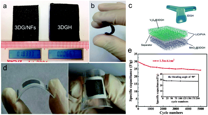 | ||
| Fig. 12 (a) Photo images of 3D graphene/Ni foam (3DG/NFs) and 3D hollow graphene (3DGH) samples. The insets are the mass of each sample (sample area, 6 cm2). (b) An illustration of the flexibility of the 3DGH sample. (c) A schematic illustration of the V3S4/3DGH//MnO2/3DGH device. Reprinted from ref. 100 with permission from Copyright© 2015, American Chemical Society. (d) Digital photographs show the flexible SC at bent states. (e) Cycling stability of the as assembled flexible SC collected at a current density of 1.5 mA cm−2 for 5000 cycles. The inset shows its cycling performance for bending cycles with a bending angle of 90°. Reprinted from ref. 78 with permission from Copyright© 2012, American Chemical Society. | ||
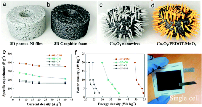 | ||
| Fig. 13 (a–d) Schematics of the fabrication process of thin 3D porous graphite foams (GF) and GF based Co3O4/PEDOT-MnO2 core/shell nanowire arrays. (e) Specific capacitance of four positive electrodes as a function of current density (it should be noted that the capacitance of a positive electrode is calculated based on the mass of the whole electrode). (f) Ragone plot of four positive electrodes. (g) Photos of the as assembled flexible asymmetric supercapacitor device. Reprinted from ref. 101 with permission from Copyright© 2014, American Chemical Society. | ||
4. Summary and prospect
Manganese oxide (MnO2) has stimulated intensive interest due to its application in the development of flexible supercapacitors owing to its outstanding features such as low-cost, high theoretical capacitance, and wide working potential window. However, one of the crucial challenges for the use of MnO2 as an electrode for flexible supercapacitors is its poor electronic and ionic conductivities, which have hindered its wider application in SCs. To overcome this challenge, intensive efforts have been devoted. In this review, recent advances in intrinsically and extrinsically modified MnO2 have been summarized, including the approach to tune the crystallinity, synthesis of MnO2 with certain targeted crystal structure, oxygen vacancy introduction, construction of flexible non-3D and 3D architecture composites. The integration of MnO2 into low-dimensional supports with high surface areas, and highly conductive and flexible 3D scaffolds could achieve high specific capacitance close to the theoretical value and good rate capability. While, the mass loading of MnO2 in most of the reports is limited below 1 mg cm−2, which is meaningless to flexible SCs at a practical level since it will result in a super low volumetric capacitance. Moreover, the interfacial problems between the MnO2 and the conductive support are still rarely investigated. Due to the introduction of oxygen vacancies into MnO2, the electronic conductivity is enhanced significantly. However, the concentration of oxygen vacancies cannot be introduced controllably. In particular, there is still lack of a facile, efficient method to introduce oxygen vacancies into bulk MnO2 instead of just the surface. Given these unresolved problems or challenges, the following aspects might be possible ways to develop really applicable MnO2 electrodes with ultrahigh energy density and power density for flexible SCs:1. The mass loading of commercial level (∼10 mg cm−2) for MnO2 active materials has already been achieved via various approaches.17,102 However, the specific capacitance is still too far from the theoretical value (∼1370 F g−1), i.e., MnO2/Graphene gel/NFs (234 F g−1, 13.61 mg cm−2, 10 mV s−1),17 graphene–MnO2 composites (147 F g−1, 9.6 mg cm−2, 2 mV s−1),78 MnO2-CNT-textile (337 F g−1, 8.3 mg cm−2, 0.05 mV s−1),102 MnO2-PEDOT:PSS composites (196 F g−1, 8.5 mg cm−2, 0.5 mA cm−2),103 even comparable with commercial activated carbon. The integration with high-surface area carbon or other conductive materials is a common approach for MnO2 to achieve high capacitive performance at a high mass loading level. However, since the limitation of MnO2 with high mass loading is the electronic transport in its phase, the intrinsic modification should be the efficient way. In this regard, further investigation might better be focused on the oxygen vacancy introduction to pursue fast electronic transport and high capacitance at a high mass loading level.
2. Introduction of oxygen vacancies, as one of the most efficient methods to intrinsically improve the electronic conductivities, has drawn intensive attention in recent years. Various approaches including annealing in de-oxygen atmosphere, atomic or ion doping are adopted to introduce oxygen vacancies into the MnO2 active materials. Enhanced electrochemical properties of MnO2 have been achieved by the oxygen vacancy introduction. However, these kinds of methods can only introduce the deficiency into the surface area of MnO2. With respect to MnO2 at a high mass loading, the contribution of the oxygen vacancies is limited to the electrochemical performance of the MnO2 electrodes. Thus, further investigations of new methods to introduce the oxygen vacancies into the bulk or inactive phase of MnO2 might be valuable for MnO2 based flexible SCs.
3. The mechanical properties of 3D conductive scaffolds are still a major concern for their application in flexible SCs. The flexible, wearable electronics have raised critical requirements such as stretch ability, flexibility and twist ability for the flexible SCs and also the electrode. Nevertheless, the 3D scaffolds for MnO2 active materials in the current study involve the construction of 3D structures. Their flexibility is usually realized via impregnation of elastic polymers like PMMA,78 which will remarkably hinder the electron transport and prevent the porous structure from the electrolyte ions. Therefore, new modifications of existing 3D scaffolds such as 3D graphene foam or graphene hydrogel and/or construction of a new type of 3D scaffold need to be developed.
Author contributions
The manuscript was written through the contributions of all the authors. All the authors have given approval to the final version of the manuscript.Conflict of interest
The authors declare no competing financial interest.Acknowledgements
We acknowledge the financial support of this work received by the Natural Science Foundation of China (21403306 and 21273290), Guangdong Province Natural Science Foundation for Distinguished Young Project (2014A030306048), Foundation for Youth Innovative Talents in Higher Education of Guangdong (2014KQNCX003) and The Research Foundation of IARC-SYSU (201408).References
- T. Mahlia, T. Saktisahdan, A. Jannifar, M. Hasan and H. Matseelar, Renewable Sustainable Energy Rev., 2014, 33, 532–545 CrossRef PubMed.
- M. I. Hoffert, K. Caldeira, G. Benford, D. R. Criswell, C. Green, H. Herzog, A. K. Jain, H. S. Kheshgi, K. S. Lackner and J. S. Lewis, Science, 2002, 298, 981–987 CrossRef CAS PubMed.
- P. Simon, Y. Gogotsi and B. Dunn, Science, 2014, 343, 1210–1211 CrossRef CAS PubMed.
- G. Wang, L. Zhang and J. Zhang, Chem. Soc. Rev., 2012, 41, 797–828 RSC.
- B. E. Conway, Electrochemical supercapacitors: scientific fundamentals and technological applications, Springer Science & Business Media, 2013 Search PubMed.
- B. D. Gates, Science, 2009, 323, 1566–1567 CrossRef CAS PubMed.
- X. Lu, M. Yu, G. Wang, Y. Tong and Y. Li, Energy Environ. Sci., 2014, 7, 2160–2181 Search PubMed.
- J. R. Miller and P. Simon, Science, 2008, 321, 651–652 CrossRef CAS PubMed.
- M. D. Stoller, S. Park, Y. Zhu, J. An and R. S. Ruoff, Nano Lett., 2008, 8, 3498–3502 CrossRef CAS PubMed.
- H. M. Jeong, J. W. Lee, W. H. Shin, Y. J. Choi, H. J. Shin, J. K. Kang and J. W. Choi, Nano Lett., 2011, 11, 2472–2477 CrossRef CAS PubMed.
- M. F. El-Kady, V. Strong, S. Dubin and R. B. Kaner, Science, 2012, 335, 1326–1330 CrossRef CAS PubMed.
- K. H. An, W. S. Kim, Y. S. Park, Y. C. Choi, S. M. Lee, D. C. Chung, D. J. Bae, S. C. Lim and Y. H. Lee, Adv. Mater., 2001, 13, 497–500 CrossRef CAS.
- D. N. Futaba, K. Hata, T. Yamada, T. Hiraoka, Y. Hayamizu, Y. Kakudate, O. Tanaike, H. Hatori, M. Yumura and S. Iijima, Nat. Mater., 2006, 5, 987–994 CrossRef CAS PubMed.
- J. Gamby, P. Taberna, P. Simon, J. Fauvarque and M. Chesneau, J. Power Sources, 2001, 101, 109–116 CrossRef CAS.
- K. Naoi and P. Simon, Interfaces, 2008, 17, 34–37 CAS.
- J. Cao, X. Li, Y. Wang, F. C. Walsh, J.-H. Ouyang, D. Jia and Y. Zhou, J. Power Sources, 2015, 293, 657–674 CrossRef CAS PubMed.
- T. Zhai, F. Wang, M. Yu, S. Xie, C. Liang, C. Li, F. Xiao, R. Tang, Q. Wu and X. Lu, Nanoscale, 2013, 5, 6790–6796 RSC.
- J. Wei, N. Nagarajan and I. Zhitomirsky, J. Mater. Process. Technol., 2007, 186, 356–361 CrossRef CAS PubMed.
- S. Park, H.-W. Shim, C. W. Lee, H. J. Song, I. J. Park, J.-C. Kim, K. S. Hong and D.-W. Kim, Nano Res., 2015, 8, 990–1004 CrossRef CAS.
- A. Boisset, L. Athouel, J. Jacquemin, P. Porion, T. Brousse and M. R. M. Anouti, J. Phys. Chem. C, 2013, 117, 7408–7422 CAS.
- H. Y. Wang, F. X. Xiao, L. Yu, B. Liu and X. W. D. Lou, Small, 2014, 10, 3181–3186 CrossRef CAS PubMed.
- L. Peng, X. Peng, B. Liu, C. Wu, Y. Xie and G. Yu, Nano Lett., 2013, 13, 2151–2157 CrossRef CAS PubMed.
- S. Devaraj and N. Munichandraiah, J. Phys. Chem. C, 2008, 112, 4406–4417 CAS.
- L. Athouël, F. Moser, R. Dugas, O. Crosnier, D. Bélanger and T. Brousse, J. Phys. Chem. C, 2008, 112, 7270–7277 Search PubMed.
- H. Xu, X. Hu, H. Yang, Y. Sun, C. Hu and Y. Huang, Adv. Energy Mater., 2015, 5, 1401882 Search PubMed.
- P. Yang, Y. Ding, Z. Lin, Z. Chen, Y. Li, P. Qiang, M. Ebrahimi, W. Mai, C. P. Wong and Z. L. Wang, Nano Lett., 2014, 14, 731–736 CrossRef CAS PubMed.
- P. Yang, Y. Li, Z. Lin, Y. Ding, S. Yue, C. P. Wong, X. Cai, S. Tan and W. Mai, J. Mater. Chem. A, 2014, 2, 595–599 CAS.
- F. Lai, Y.-E. Miao, Y. Huang, T.-S. Chung and T. Liu, J. Phys. Chem. C, 2015, 119, 13442–13450 CAS.
- X. Li, G. Wang, X. Wang, X. Li and J. Ji, J. Mater. Chem. A, 2013, 1, 10103–10106 CAS.
- P. Xu, B. Wei, Z. Cao, J. Zheng, K. Gong, F. Li, J. Yu, Q. Li, W. Lu and J.-H. Byun, ACS Nano, 2015, 9, 6088–6096 CrossRef CAS PubMed.
- H. Xu, X. Hu, Y. Sun, H. Yang, X. Liu and Y. Huang, Nano Res., 2015, 8, 1148–1158 CrossRef CAS.
- Y. Huang, Y. Li, Z. Hu, G. Wei, J. Guo and J. Liu, J. Mater. Chem. A, 2013, 1, 9809–9813 CAS.
- J. A. Dawson and I. Tanaka, ACS Appl. Mater. Interfaces, 2014, 6, 17776–17784 CAS.
- D. A. Tompsett, S. C. Parker and M. S. Islam, J. Mater. Chem. A, 2014, 2, 15509–15518 CAS.
- J. A. Dawson, H. Chen and I. Tanaka, ACS Appl. Mater. Interfaces, 2015, 7, 1726–1734 CAS.
- T. Zhai, S. Xie, M. Yu, P. Fang, C. Liang, X. Lu and Y. Tong, Nano Energy, 2014, 8, 255–263 CrossRef CAS PubMed.
- H. Y. Lee and J. B. Goodenough, J. Solid State Chem., 1999, 144, 220–223 CrossRef CAS.
- X. Lu, T. Zhai, X. Zhang, Y. Shen, L. Yuan, B. Hu, L. Gong, J. Chen, Y. Gao and J. Zhou, Adv. Mater., 2012, 24, 938–944 CrossRef CAS PubMed.
- X. Lu, D. Zheng, T. Zhai, Z. Liu, Y. Huang, S. Xie and Y. Tong, Energy Environ. Sci., 2011, 4, 2915–2921 CAS.
- M. Toupin, T. Brousse and D. Bélanger, Chem. Mater., 2004, 16, 3184–3190 CrossRef CAS.
- M. J. Young, A. M. Holder, S. M. George and C. B. Musgrave, Chem. Mater., 2015, 27, 1172–1180 CrossRef CAS.
- P. Simon and Y. Gogotsi, Nat. Mater., 2008, 7, 845–854 CrossRef CAS PubMed.
- Y. T. Weng, H. A. Pan, R. C. Lee, T. Y. Huang, Y. Chu, J. F. Lee, H. S. Sheu and N. L. Wu, Adv. Energy Mater., 2015, 5, 1500772 Search PubMed.
- Q. Li, X.-F. Lu, H. Xu, Y.-X. Tong and G.-R. Li, ACS Appl. Mater. Interfaces, 2014, 6, 2726–2733 CAS.
- J. Yan, A. Sumboja, X. Wang, C. Fu, V. Kumar and P. S. Lee, Small, 2014, 10, 3568–3578 CrossRef CAS PubMed.
- C.-K. Lin, K.-H. Chuang, C.-Y. Lin, C.-Y. Tsay and C.-Y. Chen, SuCT, 2007, 202, 1272–1276 CAS.
- J.-K. Chang, Y.-L. Chen and W.-T. Tsai, J. Power Sources, 2004, 135, 344–353 CrossRef CAS PubMed.
- C. M. Ghimbeu, A. Malak-Polaczyk, E. Frackowiak and C. Vix-Guterl, J. Appl. Electrochem., 2014, 44, 123–132 CrossRef.
- S. Donne, A. Hollenkamp and B. Jones, J. Power Sources, 2010, 195, 367–373 CrossRef CAS PubMed.
- T. Brousse, M. Toupin, R. Dugas, L. Athouël, O. Crosnier and D. Bélanger, J. Electrochem. Soc., 2006, 153, A2171–A2180 CrossRef CAS PubMed.
- Y.-C. Chen, Y.-K. Hsu, Y.-G. Lin, Y.-K. Lin, Y.-Y. Horng, L.-C. Chen and K.-H. Chen, Electrochim. Acta, 2011, 56, 7124–7130 CrossRef CAS PubMed.
- Y. Hu, H. Zhu, J. Wang and Z. Chen, J. Alloys Compd., 2011, 509, 10234–10240 CrossRef CAS PubMed.
- J. Lin, C. Zhang, Z. Yan, Y. Zhu, Z. Peng, R. H. Hauge, D. Natelson and J. M. Tour, Nano Lett., 2012, 13, 72–78 CrossRef PubMed.
- D. Pech, M. Brunet, H. Durou, P. Huang, V. Mochalin, Y. Gogotsi, P.-L. Taberna and P. Simon, Nat. Nanotechnol., 2010, 5, 651–654 CrossRef CAS PubMed.
- J. Chmiola, C. Largeot, P.-L. Taberna, P. Simon and Y. Gogotsi, Science, 2010, 328, 480–483 CrossRef CAS PubMed.
- G. Han, Y. Liu, L. Zhang, E. Kan, S. Zhang, J. Tang and W. Tang, Sci. Rep., 2014, 4, 4824 Search PubMed.
- W. Zilong, Z. Zhu, J. Qiu and S. Yang, J. Mater. Chem. C, 2014, 2, 1331–1336 RSC.
- B. You, N. Li, H. Zhu, X. Zhu and J. Yang, ChemSusChem, 2013, 6, 474–480 CrossRef CAS PubMed.
- W. Li, K. Xu, B. Li, J. Sun, F. Jiang, Z. Yu, R. Zou, Z. Chen and J. Hu, ChemElectroChem, 2014, 1, 1003–1008 CrossRef CAS PubMed.
- H. Jiang, T. Zhao, J. Ma, C. Yan and C. Li, Chem. Commun., 2011, 47, 1264–1266 RSC.
- J. A. Lee, M. K. Shin, S. H. Kim, H. U. Cho, G. M. Spinks, G. G. Wallace, M. D. Lima, X. Lepró, M. E. Kozlov and R. H. Baughman, Nat. Commun., 2013, 4, 1970 Search PubMed.
- X. Xiao, T. Li, P. Yang, Y. Gao, H. Jin, W. Ni, W. Zhan, X. Zhang, Y. Cao and J. Zhong, ACS Nano, 2012, 6, 9200–9206 CrossRef CAS PubMed.
- X. Wang, B. Liu, R. Liu, Q. Wang, X. Hou, D. Chen, R. Wang and G. Shen, Angew. Chem., 2014, 126, 1880–1884 CrossRef PubMed.
- K. Jost, D. Stenger, C. R. Perez, J. K. McDonough, K. Lian, Y. Gogotsi and G. Dion, Energy Environ. Sci., 2013, 6, 2698–2705 CAS.
- Z. Yang, J. Deng, X. Chen, J. Ren and H. Peng, Angew. Chem., Int. Ed., 2013, 52, 13453–13457 CrossRef CAS PubMed.
- Y. Zhang, W. Bai, X. Cheng, J. Ren, W. Weng, P. Chen, X. Fang, Z. Zhang and H. Peng, Angew. Chem., Int. Ed., 2014, 53, 14564–14568 CrossRef CAS PubMed.
- T. Chen, R. Hao, H. Peng and L. Dai, Angew. Chem., Int. Ed., 2015, 54, 618–622 CAS.
- J. Yang, X. Zhou, W. James, S. Malik and C. Wang, 2004, arXiv preprint cond-mat/0409345.
- M.-K. Song, S. Cheng, H. Chen, W. Qin, K.-W. Nam, S. Xu, X.-Q. Yang, A. Bongiorno, J. Lee and J. Bai, Nano Lett., 2012, 12, 3483–3490 CrossRef CAS PubMed.
- F. Cheng, T. Zhang, Y. Zhang, J. Du, X. Han and J. Chen, Angew. Chem., Int. Ed., 2013, 52, 2474–2477 CrossRef CAS PubMed.
- Y. Li and H. Xie, Ionics, 2010, 16, 21–25 CrossRef CAS.
- G. Zhang, L. Zheng, M. Zhang, S. Guo, Z.-H. Liu, Z. Yang and Z. Wang, Energy Fuels, 2011, 26, 618–623 CrossRef.
- Q. Ye, R. Dong, Z. Xia, G. Chen, H. Wang, G. Tan, L. Jiang and F. Wang, Electrochim. Acta, 2014, 141, 286–293 CrossRef CAS PubMed.
- L. Mai, H. Li, Y. Zhao, L. Xu, X. Xu, Y. Luo, Z. Zhang, W. Ke, C. Niu and Q. Zhang, Sci. Rep., 2013, 3, 1718 Search PubMed.
- C. Chen, K. Xu, X. Ji, B. Zhang, L. Miao and J. Jiang, J. Mater. Chem. A, 2015, 3, 9909–9914 Search PubMed.
- D. Su, S. Dou and G. Wang, Sci. Rep., 2014, 4, 5767 CrossRef PubMed.
- J. Kang, A. Hirata, L. Kang, X. Zhang, Y. Hou, L. Chen, C. Li, T. Fujita, K. Akagi and M. Chen, Angew. Chem., 2013, 125, 1708–1711 CrossRef PubMed.
- Y. He, W. Chen, X. Li, Z. Zhang, J. Fu, C. Zhao and E. Xie, ACS Nano, 2012, 7, 174–182 CrossRef PubMed.
- L. Yuan, X.-H. Lu, X. Xiao, T. Zhai, J. Dai, F. Zhang, B. Hu, X. Wang, L. Gong and J. Chen, ACS Nano, 2011, 6, 656–661 CrossRef PubMed.
- Y. Jin, H. Chen, M. Chen, N. Liu and Q. Li, ACS Appl. Mater. Interfaces, 2013, 5, 3408–3416 CAS.
- Y. Cheng, S. Lu, H. Zhang, C. V. Varanasi and J. Liu, Nano Lett., 2012, 12, 4206–4211 CrossRef CAS PubMed.
- Z. Zhang, F. Xiao, L. Qian, J. Xiao, S. Wang and Y. Liu, Adv. Energy Mater., 2014, 4, 1400064 Search PubMed.
- L. Bao, J. Zang and X. Li, Nano Lett., 2011, 11, 1215–1220 CrossRef CAS PubMed.
- J. Tao, N. Liu, W. Ma, L. Ding, L. Li, J. Su and Y. Gao, Sci. Rep., 2013, 3, 2283 Search PubMed.
- X. Lu, M. Yu, G. Wang, T. Zhai, S. Xie, Y. Ling, Y. Tong and Y. Li, Adv. Mater., 2013, 25, 267–272 CrossRef CAS PubMed.
- X. Peng, L. Peng, C. Wu and Y. Xie, Chem. Soc. Rev., 2014, 43, 3303–3323 RSC.
- Y. Shao, H. Wang, Q. Zhang and Y. Li, J. Mater. Chem. C, 2013, 1, 1245–1251 RSC.
- Y. Cheng, H. Zhang, S. Lu, C. V. Varanasi and J. Liu, Nanoscale, 2013, 5, 1067–1073 RSC.
- Q. Wang, J. Xu, X. Wang, B. Liu, X. Hou, G. Yu, P. Wang, D. Chen and G. Shen, ChemElectroChem, 2014, 1, 559–564 CrossRef PubMed.
- W. Chen, Y. He, X. Li, J. Zhou, Z. Zhang, C. Zhao, C. Gong, S. Li, X. Pan and E. Xie, Nanoscale, 2013, 5, 11733–11741 RSC.
- T. Qiu, B. Luo, M. Giersig, E. M. Akinoglu, L. Hao, X. Wang, L. Shi, M. Jin and L. Zhi, Small, 2014, 10, 4136–4141 CAS.
- T. G. Yun, B. I. Hwang, D. Kim, S. Hyun and S. M. Han, ACS Appl. Mater. Interfaces, 2015, 7, 9228–9234 CAS.
- J. S. Kim, S. S. Shin, H. S. Han, L. S. Oh, D. H. Kim, J.-H. Kim, K. S. Hong and J. Y. Kim, ACS Appl. Mater. Interfaces, 2013, 6, 268–274 Search PubMed.
- M. Kaempgen, C. K. Chan, J. Ma, Y. Cui and G. Gruner, Nano Lett., 2009, 9, 1872–1876 CrossRef CAS PubMed.
- Y. J. Kang, H. Chung, C.-H. Han and W. Kim, Nanotechnology, 2012, 23, 065401 CrossRef PubMed.
- H. Jiang, C. Li, T. Sun and J. Ma, Chem. Commun., 2012, 48, 2606–2608 RSC.
- A. L. M. Reddy, M. M. Shaijumon, S. R. Gowda and P. M. Ajayan, Nano Lett., 2009, 9, 1002–1006 CrossRef CAS PubMed.
- G. Yu, L. Hu, N. Liu, H. Wang, M. Vosgueritchian, Y. Yang, Y. Cui and Z. Bao, Nano Lett., 2011, 11, 4438–4442 CrossRef CAS PubMed.
- M. Yu, W. Qiu, F. Wang, T. Zhai, P. Fang, X. Lu and Y. Tong, J. Mater. Chem. A, 2015, 3, 15792–15823 CAS.
- T. Zhai, X. Lu, H. Wang, G. Wang, T. Mathis, T. Liu, C. Li, Y. Tong and Y. Li, Nano Lett., 2015, 15, 3189–3194 CrossRef CAS PubMed.
- X. Xia, D. Chao, Z. Fan, C. Guan, X. Cao, H. Zhang and H. J. Fan, Nano Lett., 2014, 14, 1651–1658 CrossRef CAS PubMed.
- L. Hu, W. Chen, X. Xie, N. Liu, Y. Yang, H. Wu, Y. Yao, M. Pasta, H. N. Alshareef and Y. Cui, ACS Nano, 2011, 5, 8904–8913 CrossRef CAS PubMed.
- Z. Su, C. Yang, C. Xu, H. Wu, Z. Zhang, T. Liu, C. Zhang, Q. Yang, B. Li and F. Kang, J. Mater. Chem. A, 2013, 1, 12432–12440 CAS.
- X. Wang and Y. D. Li, J. Am. Chem. Soc., 2002, 124(12), 2880–2881 CrossRef CAS PubMed.
- B. Solomon, J. J. Wu, E. Thomsen, J. B. Yang and X. D. Zhou, ECS Meet. Abstr., 2012, MA2012, 02, 1960.
- Y. Huang, Y. Y. Li, Z. Q. Hu, G. M. Wei, J. L. Guo and J. P. Liu, J. Mater. Chem. A, 2013, 1, 9809 CAS.
| This journal is © The Royal Society of Chemistry 2016 |


