A systematic approach to design task-specific ionic liquids and their optimal operating conditions
Received
29th December 2015
, Accepted 18th March 2016
First published on 5th April 2016
Abstract
Carbon capture and storage (CCS) has gained great interest in recent years as a potential technology to mitigate industrial carbon dioxide (CO2) emissions. Ionic liquids (ILs) were identified as potential CO2 capturing solvents, due to their negligible vapour pressure, high thermal stability, and wide range of thermophysical properties. However, determining a task-specific IL merely through experimental studies is tedious and costly, as there are about a million possible combinations of cations and anions that may make up the ILs. This work presents a systematic approach to design an optimal IL for the purpose of carbon capture. The significant contribution of the presented approach in this work is the introduction of disjunctive programming to identify optimal operating conditions of the process involved while solving the IL synthesis problem. As studies show, the performance of ILs changes with the operating conditions, which in turn affects overall performance of the carbon capture process. Hence, the presented approach will determine the optimal IL by considering the effect of system operating conditions, and simultaneously determining optimal conditions of the carbon capture process. Operating conditions of the process are modelled as continuous variables; disjunctive programming can discretise these variables and reduce search space for results. Since most of the ILs to be designed are novel solvents, their thermophysical properties are estimated using the group contribution (GC) method. Appropriate structural constraints are defined to ensure the structure of the synthesised IL is feasible. An illustrative case study is solved to demonstrate the proposed approach.
1. Introduction
Climate change is one of the most critical environmental problems faced by the global community currently, with the atmospheric carbon dioxide (CO2) concentration already exceeded the safe limits in recent years.1 The growing concern about the impact of climate change has driven research efforts towards reduction of CO2 emissions. Carbon capture and storage (CCS) is introduced as an interesting option to mitigate climate change, as it allows the usage of fossil fuels while stabilising the atmospheric CO2 concentrations.2 In general, CCS involves carbon capture which is separating CO2 from combustion flue gas, followed by carbon storage in an appropriate geological storage reservoir. Among all potential technologies for CO2 separation, absorption using amine based solvents is the most established CO2 separation approach.3 However, amine based solvents possess some disadvantages such as solvent loss due to high vapour pressure, degradation of solvent in the presence of pollutants,4 and high equipment corrosion rate.5 Besides, using amines as solvents is uneconomical as a large absorber volume is required and the solvent regeneration process is energy intensive.6
To avoid these problems, ionic liquids (ILs), which are salts that remain as a liquid around room temperature, have been proposed to replace the harmful volatile organic compounds (VOCs).7 ILs consist of large organic cations and anions (can either be organic or inorganic) of smaller size and asymmetrical shape.8 An example of an IL is shown in Fig. 1. The group on the left in Fig. 1, which is relatively large and denoted with a positive sign in the ring is an imidazolium ion (i.e. a cation), while the group on the right is a chloride ion (i.e. an anion). Due to the Coulombic attraction between ions of the liquids,9 ILs exhibit no measurable vapour pressure at room temperature and are generally quite stable over a wide temperature range.10 Therefore ILs do not contribute to emission of harmful compounds and they are “green” solvents compared to traditional VOCs. ILs are reported to be good solvents for inorganic and organic components and they are capable of dissolving a vast range of inorganic molecules to very high concentrations, by reducing by-products from side reactions.11 Furthermore, their physical and chemical properties can be finely customised by a suitable choice of cations and anions.12 However, some ILs are expensive and feature a few undesirable properties too, including high toxicity, and corrosiveness.12 Nevertheless, the other properties of ILs are important from an industrial point of view, and thus ILs are reported for various industrial applications.
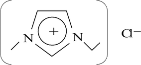 |
| | Fig. 1 Chemical structure of 1-ethyl-3-methylimidazolium chloride.13 | |
Based on the aforementioned characteristics of ILs, the concept of using ILs as a carbon capture solvent is gaining interest. Blanchard et al.14 first reported that CO2 is highly soluble in imidazolium-based ILs, and the dissolution of CO2 in ILs is completely reversible where a relatively pure IL remains after the absorption process. Maginn15 showed that ILs is a viable technical option for post-combustion capture, for many of the problems associated with current carbon capture solvents can be overcome by properly tuning the properties of ILs. Hasib-ur-Rahman et al.16 reviewed on a variety of techniques using ILs, and suggested that carbon capture by ILs is a feasible practice, if there are inexpensive and diverse ILs. Wappel et al.17 made comparison between a large range of ILs (of different purities) and 30 wt% of monoethanolamine (MEA) solvent and concluded that the regeneration energy demand of ILs is lower than that of MEA, due to the physical absorption mechanism of ILs.18 Apart from physical absorption, Yokozeki et al.19 showed that CO2 can be absorbed through chemical absorption by ILs with acetate anion, to very high CO2 solubility. Subsequently, more anion-functionalised ILs have been reported for efficient CO2 capture such as amino acid anions,20 azolate anions,21 and phenolate anions.22 All the aforementioned studies show that ILs are promising substitutes to the conventional carbon capture solvents, through a suitable match of cations and anions.
According to Plechkova and Seddon,23 there exist at least 106 unique combinations of cations and anions, which makes the identification of optimal task-specific ILs through experiments a very challenging task. Computer-aided techniques are interesting options to solve an IL design problem, because they can accelerate the discovery and development of suitable molecular structure,24 and improve the efficiency of the IL design process at the same time.25 One of the established techniques that are recently extended for IL design is the computer-aided molecular design (CAMD) technique, where molecules or molecular structures can be determined using this technique from a given set of building blocks to match a specified set of target properties.26 Matsuda et al.27 presented the design of ILs, based on the quantitative structure–property relationship coupled with a descriptor of group contribution (GC). A program was built using the presented work to reverse design ILs, considering the ionic conductivities and viscosities of ILs. McLeese et al.28 applied the CAMD approach to design ILs to be used in conjunction with refrigerants, within an absorption refrigeration system. The computational efficiency of different algorithms (CPLEX and Tabu search) in solving the problem is compared. However, the design of cation was not considered in this work, which reduces the complexity of the optimisation problem. Chávez-Islas et al.29 presented a mixed integer nonlinear programming (MINLP) formulation for optimal design of ILs to recover high purity ethanol from an ethanol–water system, where ILs were designed to break the ethanol–water azeotrope. A UNIFAC model was employed in this work to describe the equilibrium relationship, and process restrictions were considered as well in the formulation. This work was extended to include simultaneous design of an extractive distillation column.30 Roughton et al.31 also proposed to design IL entrainers and azeotropic separation processes at once, using a newly developed solubility parameter model that is based on the GC method and the UNIFAC-IL model. Hada et al.32 developed a methodology to combine the characterisation based method, chemometric and property clustering techniques in designing ILs. Karunanithi and Mehrkesh33 presented a general framework that can be applied for computer-aided IL design, by decomposing the problem into an ordered set of subproblems. Chong et al.34 applied the CAMD approach to design ILs specifically for carbon capture, by including appropriate structural constraints.
The aforementioned studies focus on designing suitable ILs under fixed operating conditions, which limits the potential of ILs since they exhibit different performances under varied operating conditions. Taking CO2 solubility of ILs as an example, CO2 solubility in [BMIm][PF6] increases with pressure;35 while CO2 solubility in [BMIm][BF4] decreases when temperature increases.36 Therefore, the performance of ILs determined under fixed conditions is not necessarily the optimal for a wide range of operating temperatures and pressures in a given process. As such it is necessary to identify the optimal operating conditions of the synthesised ILs during the product design stage. The contribution of this paper is the introduction to identification of the optimal operating conditions simultaneously in solving the IL design problem. Operating conditions (i.e. temperature and pressure) of a system will be modelled as continuous variables, but this causes increase in search space for optimal solution and the problem can be computationally complex to solve. Therefore, continuous variables of operating conditions are discretised, with the use of disjunctive programming in the proposed approach. Using this proposed approach, the search space for the optimal IL solvent and its optimal operating conditions can be reduced to a reasonable number, then experiments or molecular based modelling analysis can be carried out to verify the results. It is to be noted that, the accuracy of prediction also depends on the accuracy of the prediction models. However, this algorithm can be applied even when better property prediction models based on molecular structures are available in the future since the algorithm can fit different models as well. The important aspect here is to ensure that the molecule predicted has the corresponding target properties and has the same properties as predicted by the model. Since the property prediction models have errors associated with them, the propagation of error during the inverse design has to be avoided.
The rest of the work is organised below. A formal problem statement will be given in the next section. Detailed description of the disjunctive programming is included in the following section. The formulation of the IL solvent design problem as an MINLP model is described, with explanation on modelling of pure IL property constraints, process model constraints and structural constraints. An illustrative case study to design a CO2 capturing IL solvent is solved. The energy required to regenerate ILs designed for the case study is then determined through simulation and compared with that of a conventional solvent. The proposed method is also used to illustrate the effect of temperature on CO2 solubility and viscosity of different ILs. Finally, conclusions and prospects for future work are given at the end of this paper.
2. Problem statement
The main problem is aimed to design an optimal molecular structure of IL for the purpose of carbon capture, from a given set of pre-selected cation cores, anions, and organic functional groups, and to determine the optimal operating conditions for this designed IL. The designed IL should have the highest CO2 solubility at the selected conditions, while satisfying various process constraints (e.g. pure IL properties, process model, and IL structural constraints). A superstructure representation of the allowed combinations of all molecular fragments is shown in Fig. 2.
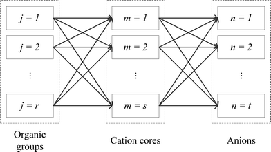 |
| | Fig. 2 Schematic representation of combinations of all molecular fragments. | |
The specific problems to be addressed are stated as follows:
1) Design an IL that is capable of absorbing the highest amount of CO2 from the groups available in the superstructure (i.e. highest CO2 solubility). The designed IL must fulfill the viscosity, process model, and IL structural constraints.
2) The superstructure is composed of r organic functional groups, s cation cores, and t anions. These groups are selected based on gas absorption and separation performance of IL beforehand.37 Since this work aims to design a pure IL for carbon capture, the choice of cation core and anion is limited to one each.
3) Operating temperature, T, and operating pressure, P, are modelled as variables so that the model will determine the optimal operating conditions for the CCS process using the chosen IL.
4) The selectivity of other gases over CO2 is assumed to be negligible in this work.
3. Disjunctive programming for discretisation of continuous variables
Since the CO2 solubility in ILs changes according to temperature and pressure, the operating conditions of the carbon capture process becomes part of the optimisation objective. Temperature and pressure can be modelled as continuous variables, which may provide good results to the optimisation problem. However, the model is more complex to be solved, because the search space for the results is much larger, compared to a model which only considers fixed operating conditions.
To avoid the aforementioned situation, the model can be simplified by using disjunctive programming, where a continuous non-linear function can be reformulated as piecewise functions over discrete domains.38 As shown in Fig. 3, the feasible operating temperatures and pressures are broken down into a few ranges. According to El-Halwagi,38 when more ranges are included, the better resemblance of the original function can be obtained. However, this is unrealistic because the total number of variables in the model will be very high and this will make the model very complex as well. Hence, a reasonable number of ranges should be selected to provide a suitable balance between accuracy in representing the function against the number of ranges. Next, operating temperatures and pressures are discretised and represented by their respective midpoints. The discretisation function with disjunctive programming can be described by the following equations.
| | | Tchoseng = Tchoseng−1Ig + Tg(1 − Ig) | (1) |
| | | (TL − Tswitchg)Ig < T − Tswitchg ≤ (TU − Tswitchg)(1 − Ig) | (2) |
| | | Pchosenh = Pchosenh−1Ih + Ph(1 − Ih) | (3) |
| | | (PL − Pswitchh)Ih < P − Pswitchh ≤ (PU − Pswitchh)(1 − Ih) | (4) |
where
TL and
TU are the lower and upper bounds to any feasible operating temperature,
PL and
PU are the lower and upper bounds for the operating pressure,
Tchoseng and
Pchosenh are the chosen system temperature range and chosen system pressure range,
Tg and
Ph are the temperature range
g and pressure range
h,
Tswitchg is the boundary temperature between temperature ranges and
Pswitchh is the boundary pressure between pressure ranges.
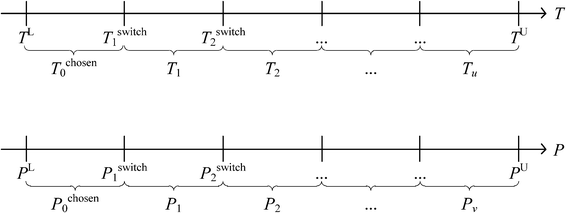 |
| | Fig. 3 Discretisation of operating temperature and pressure ranges. | |
Binary integers Ig and Ih are introduced in the model for temperature and pressure selection. In eqn (2), the first part of the inequality is always negative because Tswitchg is always larger than TL. In contrast to that, the last part of the inequality is always positive, as Tswitchg is always smaller than TU. When the temperature value T is higher than Tswitchg, the middle part of the inequality will be positive, Ig is then forced to be 0 in eqn (2) so that the inequality is valid. This also forces Tg to be chosen in eqn (1). On the other hand, if the temperature is lower than Tswitchg, Ig is forced to be 1, while Tchoseng−1 will be chosen. A similar trend occurs for pressure selection using eqn (3) and (4). By including eqn (1)–(4) in the model, whenever temperature or pressure falls into one of the pre-defined ranges, it will be represented by the midpoint of the range. For example, if any temperature value falls between TL and Tswitch1, it is now represented as Tchosen0. In this manner, the continuous variable temperature is now translated to a discrete variable. Once the operating conditions are determined, the other temperature and pressure dependent constraints will be computed according to the chosen conditions.
4. Problem formulation
A generic formulation for the IL solvent design problem similar to the previously proposed formulation is deployed in this work.34 The objective in this model is to maximise IL solvent performance, which is the CO2 solubility of IL, and all relevant constraints, including pure component properties, process model, and structural constraints, must be satisfied. Pure IL properties are estimated using suitable prediction methods (GC method in this case). Process model constraints include mass and energy balance equations, as well as conditional constraint equations, such as phase equilibrium relationships. ILs that are not structurally feasible (e.g. with a free bond or more than one cation or anion) will be excluded by the model, by including appropriate structural constraints. The main difference between this work and a previous work34 is the introduction of disjunctive programming into CAMD to simultaneously determine the optimal IL solvent and its operating pressure and temperature.
4.1. Pure component property constraints
To define property constraints, the relevant properties and suitable prediction models have to be identified first. Currently, there are a few methods available for predicting properties of ILs, while the most commonly used methods are the GC method and COSMO-RS method. The GC method is a predictive approach to predict properties of a compound only based on the molecular structure of the compound. This method has been applied on ILs recently, for different properties such as density,39 specific heat capacity,40 heat of vaporisation,41 viscosity,42 and electrical conductivity.43 The GC method is easy to use,44 but it is limited to the availability of pre-defined atomic arrangements in this method. The COSMO-RS method is a quantum chemistry based model, which was originally applied in phase equilibrium calculations, and now is extended to predict physicochemical properties of ILs, including density,45 viscosity, surface tension,46 vapour pressure,47 and gas solubility.48 The COSMO-RS method has received close attention for its independence from experimental data of the systems of interest, unlike the GC method. However, it requires the complete molecular structure as the information.35 Therefore, its application is during the final refining stage where the structures short listed using molecular design techniques can be further analysed rigorously. To solve the inverse design problem in this work, the GC method is used as they can be used to reverse engineer the molecular structure of an IL from a set of given properties. Since the challenge in molecular design is to obtain a promising structure, accuracy of GC models is sufficient.
Once the prediction method is chosen, the relevant properties should be identified. Viscosity plays an important role in this IL design problem. This is due to its effect on the CO2 capturing performance and pumping power requirement; the latter is important for solvent circulation throughout the system, which relates to its operating cost.49 An Orrick–Erbar-type approach that employs the GC method is adapted in this work to determine the viscosity of an IL.42 The approach is shown as follows:
| |  | (5) |
| |  | (6) |
| |  | (7) |
In
eqn (5),
μ is the IL viscosity in Pa s,
ρ is the IL density in g cm
−3,
M is the IL molecular weight in g mol
−1. For
eqn (6) and
(7),
vk is the number of group
k,
Ak,μ and
Bk,μ are contributions of group
k to parameters
A and
B, respectively. The IL density is required to determine the viscosity, and this can be determined using
eqn (8) and
(9).
| |  | (8) |
| |  | (9) |
Eqn (8) is the GC model for the IL density developed by Gardas and Coutinho,
50N is Avogadro's constant (given as 0.6022 mol
−1),
V is the molecular volume in Å
3, the coefficients
a,
b and
c were estimated as 0.8005, 6.652 × 10
−4 K
−1 and −5.919 × 10
−4 MPa
−1, respectively.
Eqn (9) shows that the molecular volume of an IL is equivalent to the sum of the molecular volume of each group (
Vk) that occurs in the structure.
4.2. Process model constraints
Since both gas and liquid phases are involved in carbon capture, hence equilibrium relationships are taken into consideration. The presence of organic and ionic compounds makes the liquid phase a non-ideal liquid mixture, where the nonideality can be modelled through the activity coefficient γi. Thus, the gas–liquid equilibrium can be described as:| | | yiPchosenhφi(T, P, yi) = xiγiPiS | (10) |
where xi and yi are the mole fractions of component i in the liquid and gas phases, respectively, PSi is the saturated vapour pressure of component i, and φi(T, P, yi) is the gas-phase fugacity coefficient. The CO2 solubility of a designed IL is given by this equation, in the form of mole fraction of CO2 in the liquid phase at the equilibrium.
The activity coefficient is estimated using the UNIFAC model. This model was originally developed for an organic vapour–liquid system.51 Lei et al.52 have successfully extended it to apply on systems containing ILs. According to Lei et al.,53 ILs are decomposed into a main skeleton of cation and anion, with the remaining alkyl chain connected to a cation broken down into its respective organic functional groups. As shown in Fig. 4, an example of an IL consists of an imidazolium cation with alkyl chains (R1 and R2) and a tetrafluoroborate anion. In order to apply the UNIFAC model, the cation core (i.e. the imidazole ring) is grouped with the anion; while the R1 and R2 alkyl chains are broken down into their respective organic groups.
 |
| | Fig. 4 Decomposition of an ionic liquid. | |
The UNIFAC model is a well-established method to estimate the activity coefficient and it is expressed as a function of composition and temperature, as shown in eqn (11)–(18). The model consists of a combinatorial contribution, ln γCi, which is essentially due to the differences in size and shape of the molecules, and a residual contribution, ln γRi, which is due to energetic interactions.51
The combinatorial contribution can be determined using
eqn (12)–(
14).
| |  | (12) |
| |  | (13) |
| |  | (14) |
where
xj is the mole fraction of group
j. Pure component parameters
ri are relative to the molecular van der Waals volumes; while
qi is relative to the molecular surface areas. They are calculated as the total of the group volume and group area parameters,
Rk and
Qk, respectively, as shown in
eqn (15) and (
16).
| |  | (15) |
| |  | (16) |
Residual contribution of the component can be determined as follows:
| |  | (17) |
where
Γk is the residual activity coefficient of group
k, and
Γk(i) is the residual activity of group
k in reference solution containing only molecules of type
i. These can be determined using
eqn (18)–(
20).
| |  | (18) |
| |  | (19) |
| |  | (20) |
where
Xm is the fraction of group
m in the mixture. The group interaction parameter
ψmk is defined by
eqn (21).
| | ψnm = exp![[thin space (1/6-em)]](https://www.rsc.org/images/entities/char_2009.gif) [−(anm/Tchoseng)] [−(anm/Tchoseng)] | (21) |
Parameter
anm characterises the interaction between groups
n and
m. For each group–group interaction, there are two parameters,
anm and
amn, which are not the same.
Eqn (22) is an equation of state proposed by Span and Wagner,54 which is used to determine the gas-phase fugacity coefficient. Eqn (23) is the extrapolated Antoine equation that is used to calculate the saturated vapour pressure of CO2.55
| | ln![[thin space (1/6-em)]](https://www.rsc.org/images/entities/char_2009.gif) φi = ϕr + δϕrδ − ln φi = ϕr + δϕrδ − ln![[thin space (1/6-em)]](https://www.rsc.org/images/entities/char_2009.gif) (1 + δϕrδ) (1 + δϕrδ) | (22) |
| |  | (23) |
In
eqn (22),
δ =
ρ/
ρc is the reduced density; while
Ai,
Bi, and
Ci in
eqn (23) are the coefficients of component
i. ILs have extremely low vapour pressure, hence it is assumed to be negligible in this work. For the same reason, ILs are assumed to be absent in vapour phase (
i.e.,
yIL = 0). Both
eqn (22) and (
23) are employed by Lei
et al.53 to develop a UNIFAC model specifically for ILs.
Summation of mole fractions for both phases is included as constraints to ensure that the vapour and liquid fractions always sum up to unity. These are given by eqn (24) and (25).
| |  | (24) |
| |  | (25) |
4.3. Structural constraints
Since an IL can be decomposed into electrically neutral groups, which is similar to other organic functional groups, the common structural constraints for the CAMD problem (valence and octet rules) can be applied. These ensure that the designed IL have a complete structure with no free bond, and must consist of at least two groups.| |  | (26) |
| |  | (27) |
where nk is the available free bond of group k.
In a pure IL, only one cation and one anion should occur, and therefore eqn (28) and (29) are added to enforce only one pair of cation and anion will be selected.
| |  | (28) |
| |  | (29) |
In both equations,
αm and
βn are the binary variables representing each cation
m and each anion
n, respectively.
CH3 groups present in the cation core should be quantified and added to the UNIFAC model calculation. Therefore, eqn (30) is included.
| |  | (30) |
where
gCH3 is the number of CH
3 groups in the selected cation and

is the number of CH
3 group in the individual cation structure.
4.4. Optimal molecular design
As mentioned earlier, the optimisation objective is set to design an optimal IL which will absorb the highest amount of CO2, as described by eqn (31).where xCO2,g,h stands for the liquid mole fraction of CO2 absorbed by a selected IL in the temperature range g and pressure range h. By introducing this objective function, the model will compare CO2 solubility of all possible ILs between temperature ranges g and g + 1 in eqn (1) and (2), and also between pressure ranges h and h + 1 in eqn (3) and (4). The IL, with the corresponding temperature and pressure ranges, that has the highest amount of absorbed CO2 will be chosen, and its temperature and pressure ranges will then be compared with the next temperature and pressure ranges. Taking the first two temperature ranges as examples, the first range will be T0chosen by default, and this will be compared with T1. If an IL in T1 is determined to be the optimal IL among all combinations in both temperature ranges, T1 will be chosen as T1chosen according to eqn (1). This result will then be compared with all possible ILs in T2. The comparisons will be carried out on for all pre-defined temperature ranges up to Tu; a similar procedure will be carried out for all pressure ranges.
As stated in the problem statement, the selectivity of other gases over CO2 is not considered in this work, i.e. only CO2 will be absorbed by the selected IL. The above formulation entails this as an MINLP model. The solution of this formulation will predict the molecular structures with the optimal properties. However, it is possible that many of the solutions may be difficult to synthesise or too expensive to use as a solvent. Therefore, integer cuts have been applied to produce multiple solutions in the order of their optimality to provide some flexibility for the decision maker.
5. Case study
A post-combustion carbon capture unit will be installed in a coal-fired power plant, which has a vent gas stream consisting of nitrogen, CO2, water vapour, oxygen, and some other trace gases. The compositions of these gases are given in Table 1. An IL solvent will be used in this carbon capture unit to replace the conventional MEA solvent, and the operating conditions of this unit is yet to be determined. The suitable IL solvent is to be designed using the proposed approach, together with the optimal operating conditions. Table 2 shows the molecular fragments that are available for this design problem. These fragments are chosen because they are among the most widely studied cations and anions.56 For the purpose of illustration, the feasible operating temperature range is set to be 323.15 to 373.15 K; while the feasible operating pressure range is between 0.5 and 1.0 MPa. Both the operating temperature and pressure are broken down into five ranges as illustrated in Fig. 5. These temperature and pressure ranges will be discretised using the presented approach and represented by their respective midpoints.
Table 1 Compositions of flue gases from a coal-fired power plant57
| Gas constituent |
Composition (wt%) |
| Nitrogen |
70 |
| Carbon dioxide |
15 |
| Water vapour |
10 |
| Oxygen |
4 |
| Trace gases (SOx, NOx, others) |
1 |
Table 2 Organic functional groups, cation cores, and anions considered
| Type |
k
|
Groups |
Type |
k
|
Groups |
| Organic groups |
1 |
CO2 |
Anions |
6 |
[BF4]− |
|
|
2 |
CH3 |
|
7 |
[PF6]− |
|
|
3 |
CH2 |
|
8 |
[Cl]− |
| Cation cores |
4 |
[Mim]+ |
|
|
|
|
|
5 |
[Im]+ |
|
|
|
 |
| | Fig. 5 Midpoints for all temperature and pressure ranges considered in the case study. | |
The formulation of an MINLP model for this IL design problem is given in the following equations.
| |  | (32) |
| |  | (33) |
| |  | (34) |
| |  | (35) |
| | ln![[thin space (1/6-em)]](https://www.rsc.org/images/entities/char_2009.gif) φi = ϕr + δϕrδ − ln φi = ϕr + δϕrδ − ln![[thin space (1/6-em)]](https://www.rsc.org/images/entities/char_2009.gif) (1 + δϕrδ) (1 + δϕrδ) | (36) |
| |  | (37) |
| |  | (39) |
| |  | (40) |
| |  | (41) |
| |  | (42) |
| |  | (43) |
| |  | (44) |
| |  | (45) |
| |  | (46) |
| |  | (47) |
| | ψnm = exp![[thin space (1/6-em)]](https://www.rsc.org/images/entities/char_2009.gif) [−(anm/Tchoseng)] [−(anm/Tchoseng)] | (48) |
| |  | (49) |
| |  | (50) |
| |  | (51) |
| |  | (52) |
| |  | (53) |
| |  | (54) |
Eqn (32) is the objective function formulated using
eqn (31).
Eqn (33)–
(35) are pure IL property constraints that were formulated based on
eqn (5)–
(9). The process model constraints were modelled through
eqn (37)–
(48), based on
eqn (10)–
(25). The remaining equations are structural constraints formulated from
eqn (26)–
(30). To minimise pumping costs and to increase mass transfer rates, an IL with low viscosity is desired.
42 However, it was reported that ILs have relatively high viscosities compared to common organic solvents. Generally, the viscosities of ILs range between 0.01 and 100 Pa s; while organic solvents have viscosities of about 0.0002 to 0.01 Pa s only.
58 Therefore, the upper limit was included in
eqn (34) to ensure that the viscosity of a designed IL will stay below 100 Pa s.
5.1. Optimal ionic liquid design
By solving eqn (32) subject to the constraints in eqn (33)–(52), [C14MIm][BF4] was determined as the optimal IL; while the optimal operating temperature range and pressure range were determined as 333.15 to 343.15 K and 0.90 to 1.00 MPa. These results mean that [C14MIm][BF4] has the highest CO2 solubility among all possible combinations of cations and anions in the identified temperature and pressure ranges, fulfilling all given constraints at the same time. It has a predicted solubility of 0.1558; while its viscosity is predicted to be 0.09431 Pa s, which is less than the upper limit, i.e. 0.1 Pa s. However, there is no solubility data for this IL in the literature, and hence no comparison can be conducted at this time. Nine alternative ILs are determined by doing integer cuts, along with their respective optimal operating temperature range, and the results are shown in Table 3. As shown, the results obtained by solving this model correspond to an IL that best suits the process by fulfilling all constraints, from allowed combinations of anions and cations. This means that the proposed approach provide an optimal structure of an IL for CO2 absorption, according to the given specifications or performance targets. It should be noted that there are ILs with higher CO2 solubility compared to the optimally designed ILs in Table 3, but they do not fulfill all the given constraints and hence not chosen as optimal results for the case study. The results in Table 3 show that mostly ILs with the [BF4]− anion are chosen, due to their relatively low viscosity and high CO2 solubility.
Table 3 Optimal IL molecular design results
| IL chosen |
Chosen system temperature range, Tgchosen (K) |
Chosen system pressure range, Phchosen (MPa) |
Predicted viscosity, μ (Pa s) |
Predicted solubility, xCO2,g,h |
Experimental solubility |
Relative deviation (%) |
| [C14MIm][BF4] |
333.15–343.15 |
0.90–1.00 |
0.09431 |
0.1558 |
— |
— |
| [C10MIm][BF4] |
323.15–333.15 |
0.90–1.00 |
0.08628 |
0.1515 |
— |
— |
| [C13MIm][BF4] |
333.15–343.15 |
0.90–1.00 |
0.08198 |
0.1494 |
— |
— |
| [C9MIm][BF4] |
323.15–333.15 |
0.90–1.00 |
0.07313 |
0.1429 |
— |
— |
| [C12MIm][BF4] |
333.15–343.15 |
0.90–1.00 |
0.07122 |
0.1427 |
— |
— |
| [C11MIm][BF4] |
333.15–343.15 |
0.90–1.00 |
0.06183 |
0.1358 |
— |
— |
| [C8MIm][BF4] |
323.15–333.15 |
0.90–1.00 |
0.06194 |
0.1340 |
0.14 ref. 59 |
4.29 |
| [C14MIm][BF4] |
343.15–353.15 |
0.90–1.00 |
0.05532 |
0.1332 |
— |
— |
| [C10MIm][PF6] |
333.15–343.15 |
0.90–1.00 |
0.09282 |
0.1289 |
— |
— |
| [C10MIm][BF4] |
333.15–343.15 |
0.90–1.00 |
0.05363 |
0.1287 |
— |
— |
Given that the literature data of ILs is scarce, predicted solubility was only compared to the available experimental data, using eqn (53). The relative deviations between the literature experimental solubility data and the predicted solubility data are shown in Table 3. Among all designed ILs, literature data is only available for one. The comparison shows very low relative deviations (less than 10%), and this small difference occurs mainly due to the errors present in the chosen prediction models.
| |  | (55) |
5.2. Regeneration energy of ionic liquids and monoethanolamine
For the designed ILs to be viable in industrial processes, the energy required to reproduce a high purity IL solvent should be lower than or equal to that of MEA. Therefore, the desorption process using MEA and all ten ILs shown in Table 3 is simulated using Aspen HYSYS version 8.4 for comparison.60 CO2 absorption generally occurs in the range of 40 to 60 °C; while desorption occurs around 110 to 140 °C.61 After the absorption process, the CO2 rich solvent is preheated prior to the desorption process. The simulations of the CO2 desorption process from MEA and IL solvents are shown in Fig. 6 and 7, respectively. CO2 desorption from MEA and IL are simulated based on the process described by Li et al.61 and Ali et al.62 For MEA solvent regeneration, the desorption unit is modelled as a desorber with a reboiler;61 while the desorption unit for IL solvent regeneration is modelled using a flash column.62 An NRTL fluid package is used to simulate CO2 desorption from the MEA solvent,63 because the process involves a non-ideal system and polar mixtures. On the other hand, Peng–Robinson fluid package is used for simulation of CO2 desorption from ILs, because it was shown that Peng–Robinson fluid package is suitable to model this process.62
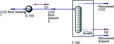 |
| | Fig. 6 Simulation of the CO2 desorption process with MEA as solvent. | |
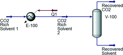 |
| | Fig. 7 Simulation of the CO2 desorption process with IL as solvent. | |
The total energy required to regenerate different solvents is shown in Table 4. The absorption temperature and pressure are the conditions of a CO2-rich solvent before entering the heater. For ILs, the absorption temperature and pressure are midpoints of the chosen ranges in the case study. As shown in Table 4, the total energy required to regenerate the MEA solvent is the highest among all, which indicates that the designed ILs using the proposed approach are suitable to replace MEA in CO2 absorption.
Table 4 Energy required for solvent regeneration
| Solvent |
Absorption temperature (K) |
Absorption pressure (MPa) |
Energy required (kJ mol−1 CO2) |
| 30 wt% MEA |
328.15 |
0.95 |
136.70 |
| [C14MIm][BF4] |
338.15 |
0.95 |
64.10 |
| [C10MIm][BF4] |
328.15 |
0.95 |
75.66 |
| [C13MIm][BF4] |
338.15 |
0.95 |
62.23 |
| [C9MIm][BF4] |
328.15 |
0.95 |
77.97 |
| [C12MIm][BF4] |
338.15 |
0.95 |
60.50 |
| [C11MIm][BF4] |
338.15 |
0.95 |
58.23 |
| [C8MIm][BF4] |
328.15 |
0.95 |
68.76 |
| [C14MIm][BF4] |
348.15 |
0.95 |
78.61 |
| [C10MIm][PF6] |
338.15 |
0.95 |
60.54 |
| [C10MIm][BF4] |
338.15 |
0.95 |
61.62 |
5.3. Effect of temperature on CO2 solubility and viscosity of ionic liquids
After the optimal ILs are obtained in the previous section, integer cuts are done further to generate more ILs at different temperature ranges. This is done to study the effect of temperature on two important properties of ILs, i.e. CO2 solubility and viscosity. The ILs that are studied in this work are all imidazolium based with one alkyl chain between C8 and C14 and one methyl group, for three different anions including tetrafluoroborate, hexafluorophosphate, and chloride. The pressure is set at 0.95 MPa in this study, which is the midpoint of the operating pressure range chosen in the case study. The results are shown in Fig. 8–13. In general, the figures show that the amount of CO2 solubility increases with the increasing carbon chain length attached to the cation core. These results tally with the literature study done by Baltus et al.,37 on CO2 solubility of different imidazolium-based ILs. Apart from that, Fig. 8, 10 and 12 also show that ILs can absorb more CO2 at a lower temperature range. This trend is similar to the experimental results shown by Karadas et al.64 In Fig. 9, 11 and 13, the IL viscosity is shown to decrease with increasing temperature. The study also shows that viscosity of ILs increases when the alkyl chain length attached to the imidazolium cation core increases. Therefore, the ILs that are chosen for CO2 absorption have longer alkyl chains, and the optimal operating temperature chosen was as low as possible.
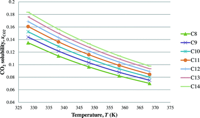 |
| | Fig. 8 Effect of temperature on CO2 solubility [CnMIm][BF4]. | |
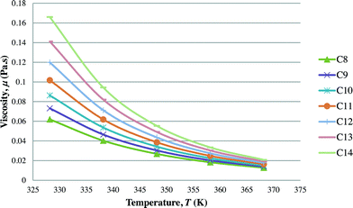 |
| | Fig. 9 Effect of temperature on viscosity of [CnMIm][BF4]. | |
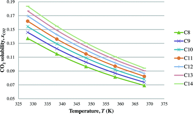 |
| | Fig. 10 Effect of temperature on CO2 solubility [CnMIm][PF6]. | |
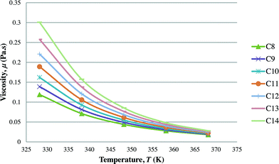 |
| | Fig. 11 Effect of temperature on viscosity of [CnMIm][PF6]. | |
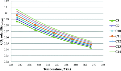 |
| | Fig. 12 Effect of temperature on CO2 solubility of [CnMIm][Cl]. | |
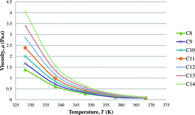 |
| | Fig. 13 Effect of temperature on viscosity of [CnMIm][Cl]. | |
Conclusions
This work demonstrates the extension of CAMD, which is a common approach for organic compound design, to design task-specific ILs by including appropriate structural constraints. The MINLP model formulated in this work can determine the optimal IL with the highest CO2 solubility, and at the same time determine the optimal operating conditions using the designed ILs. The global optimality of a solution obtained by solving this model was confirmed through integer cuts. The solubility of CO2 in ILs is predicted using an extended UNIFAC model,53 which estimates the activity coefficients of ILs and CO2. Constraints including viscosities of ILs and allowed combinations of cations, anions, and organic groups are included to ensure the designed ILs are realistic and feasible for industrial applications. Apart from the common structural constraints, cation–anion pairing constraint is added in the formulation for IL design. The optimal operating conditions are determined by using disjunctive programming. An illustrative case study is presented to show the proposed approach. Ten potential structures of ILs are obtained as results, and their optimal operating conditions are identified for this particular case study. The energy demand to regenerate these designed ILs after CO2 absorption are also determined by using Aspen HYSYS simulation, and the results are compared to MEA. The results show that ILs need a lower amount of energy during solvent regeneration, compared to MEA. The effect of temperature on CO2 solubility and viscosity of ILs is studied in this work as well. The results suggest that the lower the temperature, the higher the CO2 solubility and viscosity of ILs. Thus, the trade-off between these two properties must be evaluated during IL design for carbon capture. The proposed approach utilises GC property predictive models, and thus the design of ILs is confirmed to the list of available GC data for cation and anion groups. Future studies should focus on design of an IL mixture and include selectivity of CO2 over other gases in the model. Since the accuracy of CAMD formulation is highly dependent on property prediction models, more accurate and reliable prediction models are always needed. The accuracy and reliability of property prediction models can be improved by either updating the models, or utilising the experimental data during CAMD formulation.
Nomenclature
Abbreviations
| CAMD | Computer-aided molecular design |
| CCS | Carbon capture and storage |
| CO2 | Carbon dioxide |
| GC | Group contribution |
| IL | Ionic liquid |
| K2CO3 | Potassium carbonate |
| MEA | Monoethanolamine |
| MINLP | Mixed integer non-linear programming |
| MP | Mathematical programming |
| VOC | Volatile organic compounds |
Ionic liquids
| [MIm]+ | Methylimidazolium cation |
| [Im]+ | Imidazolium cation |
| [Cl]− | Chloride anion |
| [BF4]− | Tetrafluoroborate anion |
| [PF6]− | Hexafluorophosphate anion |
Indices
|
g
| Temperature range (g = 1, 2,…, u) |
|
h
| Pressure range (h = 1, 2,…, v) |
|
i
| Component (i = 1, 2,…, p) |
|
j
| Organic functional groups (j = 1, 2,…, r) |
|
k
| Groups (k = 1, 2,…, q) |
|
m
| Cation groups (m = 1, 2,…, s) |
|
n
| Anion groups (n = 1, 2,…, t) |
Parameters
|
a
| Coefficient in the model equation for the density |
|
a
mn
| UNIFAC group interaction parameter between groups m and n |
|
A
i
| Constant for group i in the Antoine equation |
|
A
k,μ
| Contribution of group k to parameter A |
|
b
| Coefficient in the model equation for the density |
|
B
i
| Constant for group i in the Antoine equation |
|
B
k,μ
| Contribution of group k to parameter B |
|
c
| Coefficient in the model equation for the density |
|
C
i
| Constant for group i in the Antoine equation |
|
G
m
CH3
| Number of CH3 groups in cation m |
|
N
| Avogadro's constant |
|
n
k
| Free bond number of group k |
|
Q
k
, Qm, Qn | Group surface area parameter in the UNIFAC model |
|
R
| Universal gas constant (J mol−1 K−1) |
|
R
k
| Group volume parameter in the UNIFAC model |
Variables
|
A
| Coefficient in the model equation for the viscosity |
|
B
| Coefficient in the model equation for the viscosity |
|
F
i
| Auxiliary properties for component i (surface fraction/mole fraction) |
|
g
CH3
| Number of CH3 groups in the selected cation |
|
I
g
| Binary variable for temperature range selection |
|
I
h
| Binary variable for pressure range selection |
|
M
| Molecular weight (g mol−1) |
|
P
h
chosen
| Chosen system pressure in range h (MPa) |
|
P
h
switch
| Boundary pressure between pressure ranges |
|
P
i
S
| Saturated vapour pressure of component i (MPa) |
|
P
L
| Lower bound for the system pressure (MPa) |
|
P
U
| Upper bound for the system pressure (MPa) |
|
q
i
| Parameter relative to the molecular van der Waals surface areas of pure component i |
|
r
i
| Parameter relative to the molecular van der Waals volumes of pure component i |
|
T
g
chosen
| Chosen system temperature in range g (K) |
|
T
g
switch
| Boundary temperature between temperature ranges |
|
T
L
| Lower bound for the system temperature (K) |
|
T
U
| Upper bound for the system temperature (K) |
|
V
| Molecular volume (Å3) |
|
V
k
| Molecular volume of group k (Å3) |
|
V
i
| Auxiliary properties of component i |
|
v
k
, vm | Number of group k or m |
|
v
k
(i), vm(i) | Number of group k or m in component i |
|
x
i
| Mole fraction of component i in liquid phase |
|
x
j
| Mole fraction of group j in the mixture |
|
X
m
, Xn | Fraction of group m or n in the mixture |
|
y
i
| Mole fraction of component i in gas phase |
Greek symbols
|
α
m
| Binary variable representing cation m |
|
β
n
| Binary variable representing anion n |
|
μ
| Dynamic viscosity of component i (Pa s) |
|
ρ
| Density (g cm−3) |
|
ρ
c
| Critical density (g cm−3) |
|
δ
| Reduced density |
|
ϕ
δ
r
| Derivative of reduced dimensionless Helmholtz function |
|
φ
i
(T,P,yi) | Gas-phase fugacity coefficient of component i |
|
γ
i
| Activity coefficient of component i |
|
γ
i
C
| Combinatorial contribution to the activity coefficient of component i |
|
γ
i
R
| Residual contribution to the activity coefficient of component i |
|
Γ
K
| Residual activity coefficient of group k |
|
Γ
K
(i)
| Residual activity coefficient of group k in pure component i |
|
θ
m
| Fraction of group m in a mixture of the liquid phase |
|
ψ
nm
| Group interaction parameter |
Acknowledgements
This paper was made possible by NPRP grant no. 5-351-2-136 from the Qatar National Research Fund (a member of Qatar Foundation) and financial support from the University of Nottingham Malaysia Campus Faculty of Engineering Dean's PhD scholarship. The statements made herein are solely the responsibility of the authors.
References
- Y. Jing, J. Shi, T. Wang and R. Sussmann, Atmosphere, 2014, 5, 870–888 CrossRef.
- J. C. M. Pires, F. G. Martins, M. C. M. Alvim-Ferraz and M. Simões, Chem. Eng. Res. Des., 2011, 89, 1446–1460 CrossRef CAS.
-
M. R. M. Abu-Zahra, Z. Abbas, P. Singh and P. H. M. Feron, in Materials and processes for energy: communicating current research and technological developments, ed. A. Mendez-Vilas, Formatex Research Center, 2013, pp. 923–934 Search PubMed.
- M. Zaman and J. H. Lee, Korean J. Chem. Eng., 2013, 30, 1497–1526 CrossRef CAS.
- C.-H. Yu, C.-H. Huang and C.-S. Tan, Aerosol Air Qual. Res., 2012, 12, 745–769 CAS.
- A. A. Olajire, Energy, 2010, 35, 2610–2628 CrossRef CAS.
- G. Rai and A. Kumar, Clean Technol. Environ. Policy, 2013, 16, 1529–1536 CrossRef.
-
M. Freemantle, An Introduction to Ionic Liquids, The Royal Society of Chemistry, Cambridge, 2010 Search PubMed.
- E. D. Bates, R. D. Mayton, I. Ntai and J. H. Davis, J. Am. Chem. Soc., 2002, 124, 926–927 CrossRef CAS PubMed.
- K. N. Marsh, J. A. Boxall and R. Lichtenthaler, Fluid Phase Equilib., 2004, 219, 93–98 CrossRef CAS.
- K. R. Seddon, J. Chem. Technol. Biotechnol., 1997, 68, 351–356 CrossRef CAS.
- R. D. Rogers and K. R. Seddon, Science, 2003, 302, 792–793 CrossRef PubMed.
-
H. Miyafuji, in Ionic Liquids – New Aspects for the Future, ed. J. Kadokawa, InTech, 2013, pp. 299–314 Search PubMed.
- L. A. Blanchard, D. Hancu, E. J. Beckman and J. F. Brennecke, Nature, 1999, 399, 28–29 CrossRef.
-
E. J. Maginn, Design and Evaluation of Ionic Liquids as Novel CO2 Absorbents, Notre Dame, 2007 Search PubMed.
- M. Hasib-ur-Rahman, M. Siaj and F. Larachi, Chem. Eng. Process.: Process Intesif., 2010, 49, 313–322 CrossRef CAS.
- D. Wappel, G. Gronald, R. Kalb and J. Draxler, Int. J. Greenhouse Gas Control, 2010, 4, 486–494 CrossRef CAS.
- E. Torralba-Calleja, J. Skinner and D. Gutiérrez-Tauste, J. Chem., 2013, 2013, 1–16 CrossRef.
- A. Yokozeki, M. B. Shiflett, C. P. Junk, L. M. Grieco and T. Foo, J. Phys. Chem. B, 2008, 112, 16654–16663 CrossRef CAS PubMed.
- Y. S. Sistla and A. Khanna, Chem. Eng. J., 2015, 273, 268–276 CrossRef CAS.
- C. Wang, X. Luo, H. Luo, D. Jiang, H. Li and S. Dai, Angew. Chem., Int. Ed., 2011, 50, 4918–4922 CrossRef CAS PubMed.
- X. Luo, Y. Guo, F. Ding, H. Zhao, G. Cui, H. Li and C. Wang, Angew. Chem., Int. Ed., 2014, 53, 7053–7057 CrossRef CAS PubMed.
- N. V. Plechkova and K. R. Seddon, Chem. Soc. Rev., 2008, 37, 123–150 RSC.
-
J. C. Eslick, S. M. Shulda, P. Spencer and K. V. Camarda, in Molecular Systems Engineering, ed. C. S. Adjiman and A. Galindo, Wiley-VCH, Weinheim, Germany, 2010, pp. 173–194 Search PubMed.
- R. Gani, Chem. Eng. Res. Des., 2004, 82, 1494–1504 CrossRef CAS.
- R. Gani, Comput. Chem. Eng., 2004, 28, 2441–2457 CrossRef CAS.
- H. Matsuda, H. Yamamoto, K. Kurihara and K. Tochigi, Fluid Phase Equilib., 2007, 261, 434–443 CrossRef CAS.
- S. E. McLeese, J. C. Eslick, N. J. Hoffmann, A. M. Scurto and K. V. Camarda, Comput. Chem. Eng., 2010, 34, 1476–1480 CrossRef CAS.
- L. M. Chávez-Islas, R. Vasquez-medrano and A. Flores-tlacuahuac, Ind. Eng. Chem. Res., 2011, 50, 5153–5168 CrossRef.
- D. Valencia-marquez, A. Flores-tlacuahuac and R. Vasquez-medrano, Ind. Eng. Chem. Res., 2012, 51, 5866–5880 CrossRef CAS.
- B. C. Roughton, B. Christian, J. White, K. V. Camarda and R. Gani, Comput. Chem. Eng., 2012, 42, 248–262 CrossRef CAS.
-
S. Hada, R. H. Herring and M. R. Eden, in 23rd European Symposium on Computer Aided Process Engineering, ed. A. Kraslawski and I. Turunen, Elsevier, Amsterdam, 2013, vol. 32, pp. 955–960 Search PubMed.
- A. T. Karunanithi and A. Mehrkesh, AIChE J., 2013, 59, 4627–4640 CrossRef CAS.
- F. K. Chong, D. C. Y. Foo, F. T. Eljack, M. Atilhan and N. G. Chemmangattuvalappil, Clean Technol. Environ. Policy, 2015, 17, 1301–1312 CrossRef CAS.
- Z. Lei, C. Dai and B. Chen, Chem. Rev., 2014, 114, 1289–1326 CrossRef CAS PubMed.
- N. A. Manan, C. Hardacre, J. Jacquemin, D. W. Rooney and T. G. A. Youngs, J. Chem. Eng. Data, 2009, 54, 2005–2022 CrossRef.
- R. E. Baltus, B. H. Culbertson, S. Dai, H. Luo and D. W. DePaoli, J. Phys. Chem. B, 2004, 108, 721–727 CrossRef CAS.
-
M. M. El-Halwagi, in Sustainable Design Through Process Integration: Fundamentals and Applications to Industrial Pollution Prevention, Resource Conservation, and Profitability Enhancement, Elsevier Inc., Oxford, U.K., 2012, pp. 255–286 Search PubMed.
- Y. Qiao, Y. Ma, Y. Huo, P. Ma and S. Xia, The Journal of Chemical Thermodynamics, 2010, 42, 852–855 CrossRef CAS.
- R. L. Gardas and J. A. P. Coutinho, Ind. Eng. Chem. Res., 2008, 47, 5751–5757 CrossRef CAS.
- S. P. Verevkin, Angew. Chem., Int. Ed., 2008, 47, 5071–5074 CrossRef CAS PubMed.
- R. L. Gardas and J. A. P. Coutinho, Fluid Phase Equilib., 2008, 266, 195–201 CrossRef CAS.
- R. L. Gardas and J. A. P. Coutinho, AIChE J., 2009, 55, 1274–1290 CrossRef CAS.
- L. Constantinou, S. E. Prickett and M. L. Mavrovouniotis, Ind. Eng. Chem. Res., 1993, 32, 1734–1746 CrossRef CAS.
- J. Palomar, V. R. Ferro, J. S. Torrecilla and F. Rodriguez, Ind. Eng. Chem. Res., 2007, 46, 6041–6048 CrossRef CAS.
- J. S. Torrecilla, J. Palomar, J. García and F. Rodríguez, J. Chem. Eng. Data, 2009, 54, 1297–1301 CrossRef CAS.
- M. Diedenhofen, A. Klamt, K. Marsh and A. Schäfer, Phys. Chem. Chem. Phys., 2007, 9, 4653–4656 RSC.
- M. Gonzalez-Miquel, M. Talreja, A. L. Ethier, K. Flack, J. R. Switzer, E. J. Biddinger, P. Pollet, J. Palomar, F. Rodriguez, C. A. Eckert and C. L. Liotta, Ind. Eng. Chem. Res., 2012, 51, 16066–16073 CrossRef CAS.
- E. Kuhlmann, S. Himmler, H. Giebelhaus and P. Wasserscheid, Green Chem., 2007, 9, 233–242 RSC.
- R. L. Gardas and J. A. P. Coutinho, Fluid Phase Equilib., 2008, 263, 26–32 CrossRef CAS.
- S. Skjold-Jørgensen, B. Kolbe, J. Gmehling and P. Rasmussen, Ind. Eng. Chem. Process Des. Dev., 1979, 18, 714–722 Search PubMed.
- Z. Lei, J. Zhang, Q. Li and B. Chen, Ind. Eng. Chem. Res., 2009, 48, 2697–2704 CrossRef CAS.
- Z. Lei, C. Dai, W. Wang and B. Chen, AIChE J., 2013, 60, 716–729 CrossRef.
- R. Span and W. Wagner, J. Phys. Chem. Ref. Data, 1996, 25, 1509–1596 CrossRef CAS.
- M. B. Shiflett and A. Yokozeki, AIChE J., 2006, 52, 1205–1219 CrossRef CAS.
- F. Zhou, Y. Liang and W. Liu, Chem. Soc. Rev., 2009, 38, 2590–2599 RSC.
-
Global CCS, Institute, CO2 capture technologies: Post-Combustion Capture (PCC), Global Carbon Capture and Storage Institute, Canberra, Australia, 2012 Search PubMed.
- P. Bonhôte, A.-P. Dias, M. Armand, N. Papageorgiou, K. Kalyanasundaram and M. Grätzel, Inorg. Chem., 1996, 35, 1168–1178 CrossRef.
- K. Gutkowski, A. Shariati and C. J. Peters, J. Supercrit. Fluids, 2006, 39, 187–191 CrossRef CAS.
-
L. Sittler and D. Ajikutira, Jump Start: Aspen HYSYS V8, 2013 Search PubMed.
- X. Li, S. Wang and C. Chen, Energy Procedia, 2013, 37, 1836–1843 CrossRef CAS.
-
E. Ali, I. M. AlNashef, A. Ajbar, M. HadjKali and S. Mulyono, World Academy of Science, Engineering and Technology, 2013, vol. 7, pp. 28–33 Search PubMed.
- Y. Zhang and C.-C. Chen, Energy Procedia, 2013, 37, 1584–1596 CrossRef CAS.
- F. Karadas, B. Köz, J. Jacquemin, E. Deniz, D. W. Rooney, J. Thompson, C. T. Yavuz, M. Khraisheh, S. Aparicio and M. Atilhan, Fluid Phase Equilib., 2013, 351, 74–86 CrossRef CAS.
|
| This journal is © The Royal Society of Chemistry 2016 |
Click here to see how this site uses Cookies. View our privacy policy here.  *a
*a


![[thin space (1/6-em)]](https://www.rsc.org/images/entities/char_2009.gif) γi = ln
γi = ln![[thin space (1/6-em)]](https://www.rsc.org/images/entities/char_2009.gif) γiC + ln
γiC + ln![[thin space (1/6-em)]](https://www.rsc.org/images/entities/char_2009.gif) γiR
γiR


![[thin space (1/6-em)]](https://www.rsc.org/images/entities/char_2009.gif) [−(anm/Tchoseng)]
[−(anm/Tchoseng)]![[thin space (1/6-em)]](https://www.rsc.org/images/entities/char_2009.gif) φi = ϕr + δϕrδ − ln
φi = ϕr + δϕrδ − ln![[thin space (1/6-em)]](https://www.rsc.org/images/entities/char_2009.gif) (1 + δϕrδ)
(1 + δϕrδ)


 is the number of CH3 group in the individual cation structure.


![[thin space (1/6-em)]](https://www.rsc.org/images/entities/char_2009.gif) φi = ϕr + δϕrδ − ln
φi = ϕr + δϕrδ − ln![[thin space (1/6-em)]](https://www.rsc.org/images/entities/char_2009.gif) (1 + δϕrδ)
(1 + δϕrδ)
![[thin space (1/6-em)]](https://www.rsc.org/images/entities/char_2009.gif) γi = ln
γi = ln![[thin space (1/6-em)]](https://www.rsc.org/images/entities/char_2009.gif) γiC + ln
γiC + ln![[thin space (1/6-em)]](https://www.rsc.org/images/entities/char_2009.gif) γiR
γiR


![[thin space (1/6-em)]](https://www.rsc.org/images/entities/char_2009.gif) [−(anm/Tchoseng)]
[−(anm/Tchoseng)]


