Energy saving electrochromic windows from bistable low-HOMO level conjugated polymers†
Haijin
Shin
,
Seogjae
Seo
,
Chihyun
Park
,
Jongbeom
Na
,
Minsu
Han
and
Eunkyoung
Kim
*
Active Polymer Center for Pattern Integration, Department of Chemical and Biomolecular Engineering, Yonsei University, 50 Yonsei-ro, Seodaemun-gu, Seoul 03722, South Korea. E-mail: eunkim@yonsei.ac.kr
First published on 27th November 2015
Abstract
Energy saving electrochromic windows were established by controlling the interfacial charge transport using low-HOMO level (<−5 eV) π-conjugated polymers as bistable electrochromic films and an ionic liquid as the electrolyte. It provided a long bistability (>90 min) at the voltage-off state with a high color contrast (879 cm2 C−1).
Broader contextEnergy loss through windows is about 50% of the total energy consumption in buildings and this loss has increased significantly over the last decades. Smart windows based on electrochromic (EC) materials have emerged as energy saving technology because they change their transmittance according to the applied potential. For such a smart window, the optical memory in the voltage-off state (V-Off) is important for energy saving. Furthermore, the bistability should be imperative because no additional energy consumption is required to maintain the colored or transparent state. In this work, we demonstrate the first bistable smart window by controlling the interfacial charge transport using low-HOMO level π-conjugated polymers as EC films and an ionic liquid as the electrolyte layer. It provided a long bistability (>90 min) at V-Off with a high coloration efficiency (879 cm2 C−1). |
The ability to control the light transmission through a window has captured intense interest in the field of energy saving windows to block out or manipulate dynamic daylight. Recently, the smart window has emerged as a transparent display to propel color and light transmission technology into the realm of next generation displays, architectures, and transportation. There are several methods to control light transmission including electrochemical mirrors1 and electrochromic windows by using inorganic2 and organic materials,3 and π-conjugated polymers (CPs).4 Regarding inorganic materials, electrochromic windows (ECWs) based on WO3 are the most widely studied.2,5 Particularly, CPs undergo reversible electrochemical optical changes with a fast response, and this process has garnered increasing interest because of their tunable electronic properties, low-voltage operation, and solution processability.6 Of the various CPs, the electrochromic (EC) color and transmittance changes of poly(3,4-propylenedioxythiophene) derivatives (PRs) can reach high color contrasts,7,8 which should be particularly useful for smart windows.
Smart windows change their transmittance according to the applied potential, reducing the overall energy spending of a building by approximately 25%. It also improves quality of life by increasing comfort levels for people inside the building.9
For such an electrochemical switching window, the optical memory (OM) during the voltage-off state (V-Off) is important for energy saving windows or displays. Furthermore, the OM in both the colored and transparent states under V-Off, called bistability, should be compulsory because no additional energy consumption is required to maintain the colored (dark) or transparent state.
Unlike molecular EC dyes (e.g., viologens), which are typically dissolved in electrolyte media to generate an ECW, solid state CP films potentially limit the loss of OM caused by the diffusion of EC materials and dopant ions10 to produce rather long OMs.6,11–15 However, the color contrast of ECWs in previous examples has been low (<60% at absorption maxima (λmax)), and they require complicated processes. Although there have been many efforts, including ECWs with gel electrolytes11,14,15 and EC molecules anchored with metal oxides or rotaxanes,3,16 the bistability of ECWs has rarely been reported, and it is a major hurdle in smart windows and organic electronics, including displays. Moreover, the mechanisms to realize bistability in CPs are not well understood.
To achieve bistability in an ECW, it is important to control the spontaneous charge transfer that results in OM loss at V-Off. Fundamentally, the loss of OM is related to the charge transport between the interfaces in the ECW that consist of ITO/CP film/electrolyte/ITO. This spontaneous charge transfer (self-reaction) at V-Off can be described by eqn (1):
| (Pol*) + (A−)s ⇄ (Pol+·A−)pol + eITO− | (1) |
The interfacial electron transfer (IET) between ITO and CP films is highly influenced by the energy levels of the CPs.17 Therefore, it can be hypothesized that the redox potential of the CP can be an exclusive controller of the IET. Furthermore, at the interface between the CP film and the electrolyte, the spontaneous interfacial dopant ion transport (IDT) should be blocked by the electrochemical double layer (EDL).1
Therefore, we explored a bistable ECW by controlling the interfacial charge transport in a CP-based device. First, the effect of the redox potential on the OM was examined to control the IET, which can be unfavorable when the HOMO energy level (EHOMO) of the CPs is lower than the Fermi level (EF) of the electrode.18 Thus, a series of CPs with different EHOMO were synthesized to characterize the IET. Our structural motif was based on PRs because these can be easily chemically modified to alter their redox properties via tailor-made molecular designs and to exhibit a high color contrast. Next, the IDT was controlled by using ionic liquids,19 which form ion blocking layers through the EDLs.1 Herein, we report a bistable electrochromic window (BECW) based on a new high color contrast PR derivative that has a low EHOMO.
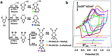
The ∼250 nm-thick CP films were easily coated on ITO glass via solution casting polymerization (SCP) of monomers (Fig. 1a).20 As shown in the cyclic voltammogram (CV) (Fig. 1b), the redox potential of the PR films was highly dependent on the monomer structure and exhibited higher oxidation peak potentials (Epox) than the poly(3,4-ethylenedioxythiophene)s (PEDOTs) in a propylene carbonate solution containing 0.1 M tetrabutylammonium perchlorate (TBAP) when using Ag/AgCl as a reference. This high Epox for the PR films can be attributed to the large alkylenedioxy group, which decreases the planarity of the polymer main chain.21,22 The CPs with electron withdrawing (Cl, Br) and bulky side groups (EHO) exhibit a higher Epox because of the electronic23,24 and steric hindrance effects,25,26 respectively. The effects of the substituents on the redox potential of the CPs in an ionic liquid medium that contained 1-butyl-3-methylimidazolium bis(trifluoromethylsulfonyl)imide (BIL) were nearly identical to those in the TBAP, except for PR-EHO (Fig. S1 and Table S1, ESI†). The EHOMO of the CP film was estimated from the CV and was confirmed by UPS (Table 1 and Fig. S5, ESI†).
| CPs | E pred [V] | E pox [V] | E 1/2 [V] | E HOMO [eV] | E LUMO [eV] | E g |
|---|---|---|---|---|---|---|
| a E Pred and EPox are based on the bigaussian multi-peak deconvolution of the cyclic voltammogram in TBAP, which was used as the electrolyte, vs. Ag/AgCl. b Half-wave potential. c The EHOMO was calculated by using EPox and estimated with the empirical relation EHOMO = −4.8e − e[EPox − E1/2Ferrocene]. d E LUMO of the CPs is determined from the EHOMO and Eg of the CPs. e E g of the CPs, as determined from the onset of the π–π* transition of the neutral-state CPs. | ||||||
| PEDOT | −0.52 (−0.631) | 0.28 (0.0131) | −0.12 | −4.65 | −2.98 | 1.67 (1.6–1.710) |
| PE-Cl | −0.42 | 0.3 | −0.06 | −4.67 | −3.02 | 1.65 |
| PR-Me | −0.18 (−0.331) | 0.4 (0.0331) | 0.11 | −4.77 | −2.9 | 1.87 |
| PR-MeO | 0.16 | 0.59 | 0.38 | −4.96 | −3.14 | 1.82 |
| PR-Br | 0.14 | 0.65 | 0.40 | −5.02 | −3.19 | 1.83 |
| PR-EHO | 0.17 (0.0826) | 0.78 (0.2526) | 0.48 | −5.15 | −3.21 | 1.94 (1.9710) |
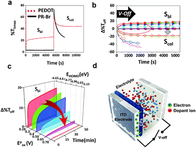
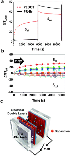
The structure of the ECW consisted of an ITO/CP film/electrolyte/ITO. To test the optical stability, the transmittance at λmax (%Tλmax) of the ECW was monitored for 90 min at V-Off in both TBAP (Fig. 2a) and BIL (Fig. 3a). Interestingly, the OM of the colored states for the PR-Br and PR-EHO were superior to those of the other polymers, and the transmittance change at λmax under V-Off (Δ%Toff) in the colored state (self-bleaching, Sbl) was almost negligible (<2%) in both TBAP and BIL (Fig. S3, ESI†). However, with PEDOT, the Δ%Toff in the colored state was 15% and 20% after 30 min in TBAP and BIL, respectively, and showed the highest change among the CPs (Fig. 2b and 3b). The OM in the colored state did not depend much on the electrolyte; however, it was highly dependent on the Epox of the CPs (Fig. 2c). When the electricity was shut off in the colored state, the spontaneous optical loss could be ascribed to the IET (Fig. 2d). This IET is possible when the EHOMO of the CPs is higher than the EF of the ITO electrode (−4.7 eV).27
The Δ%Toff of the transparent state (self-coloring, Scol) was larger than that of the colored state and was dependent on the CPs in TBAP. The Δ%Toff of PEDOT and PE-Cl were ∼20% within 30 min, which was smaller than those of the other CPs (>40%) (Fig. 2b). However, the OM in BIL was dramatically enhanced (Fig. 3a and b), possibly because of the formation of EDLs. EDLs persist for a long time even after the applied voltage is off, preventing interfacial ion transfer.1,28 Therefore, the IDT in BIL could be blocked (Fig. 3c).
The stability of the EDLs at V-Off is highly dependent on the size of the ions (Fig. S7 and S8, ESI†). The OM was shorter in BBF4 that consisted of very small anions (BF4−), which may cause an imbalance between the surface counter ions and the ion–ion steric repulsion.29 Conversely, large anions could be paired compactly with cations. Specifically, BILs have been reported to form more densely packed multi-double layers on a charged surface.30 Therefore, all of the CPs in BIL exhibited low Δ%Toff (<10%) even after 90 min (Fig. 3b, Scol), in contrast to that in TBAP.
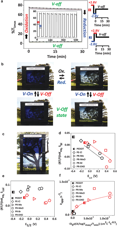
The reproducible bistability was successful in an ECW with PR-Br, exhibiting a long OM at V-Off in the colored and bleached states (Fig. 4a and b). The cyclability of the ECW was longer than 500 cycles in air (Fig. S4, ESI†). A larger-area ECW (7 inch) was also fabricated and achieved a high color contrast and a long OM (Fig. 4c).
In the colored state, the electron transfer from the CP films to the electrode is spontaneous if the EF of the electrode is below the EHOMO of the CPs (high-EHOMO) upon interface formation according to the integer charge-transfer (ICT) model.32 However, when the EF of the electrode is higher than the EHOMO of the CP film (low-EHOMO), such an electron transfer is unfavourable in the colored state (Fig. S10, ESI†).33 Therefore, the CPs with a higher EHOMO compared with the EF of the electrode (−4.7 eV) should undergo IET, whereas those with a lower EHOMO stay intact in the colored state. Indeed, this analysis agrees well with the experimental result, confirming the long OM for the CPs that have a low EHOMO or high Epox (PR-Br and PR-EHO). Thus, the IET is an exclusive controller of the OM in the colored states (Fig. 2b and c, and Table S1, ESI†). The morphology of CP films is an important factor for the charge/discharge processes that are associated with the EC properties.31,34 However, the average roughness (Ra) of the EC films did not correlate with the optical bistability (Fig. S9, ESI†). This result supports the idea that the OM in the colored state can be controlled by the IET.
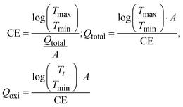
The two different mechanisms, IET and IDT, can be supported by the kinetic overpotential (ηkin)35 leading to self-reactions (Sbl and Scol) at V-Off as follows:
 | (2) |
 | (3) |
 | (4) |
 | (5) |
 | (6) |
 | (7) |
 is directly related to E1/2 during the self-reaction (eqn (7)). This showed roughly a linear relationship between
  and E1/2 for Sbl (Fig. 4d), indicating that Δ%Toff becomes smaller when Epox becomes larger (Fig. S12, ESI†). Thus, the OM in the colored state should be long with CPs having a low EHOMO. However, there is no linear relationship for Scol (Fig. 4e), indicating that the Scol process was not fully controlled by the IET. Scol should be energetically favorable for all polymers because of the small localized band gap energy.37 Under these conditions, any small driving force, such as the blocking of ion diffusion or transfer, will distract Scol.
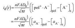
Because the doped-state CPs can be considered to be positively charged CP films that are in contact with the dopant anions, the dopant ion concentration difference between the CP films and the electrolyte interface can generate a diffusion potential (ηdiff). The diffusion potential, which is due to the anion concentration difference, can be obtained from the following eqn (8):
 | (8) |
 | (9) |
 | (10) |
 | (11) |
 | (12) |
Fig. 4f clearly displays that the self-coloring process is diffusion controlled in TBAP. kapp for Scol is proportional to the diffusion term  in TBAP. However, all of the kapp in BIL were very low and almost invariant with the
  values for different polymers, regardless of their large variations of EHOMO. This low kapp for Scol could be attributed to the EDL. Therefore, the OM in the bleached state was significantly enhanced in BIL.
Conclusions
In summary, low EHOMO level CP films afforded an energy saving bistable ECW by controlling the interfacial charge transport. The mechanism for self-bleaching was ascribed to the electron transfer between ITO and the CPs (IET), which was supported by correlating Δ%Toff with Epox of the polymers at V-off. The self-coloring process in the ECWs was explained by the ion transfer from the CPs to the electrolytes (IDT), which was blocked by the EDL, providing a long bistability for the CPs with low EHOMO. These two different mechanisms for the OM in self-bleaching (IET) and self-coloring (IDT) were supported by the energy level and diffusion term, respectively. An ECW from the new CPs (PR-Br) maintained the OM for 90 min at V-off with a large Δ%Tλmax (>70%). This allowed the first preparation of a high contrast, fast-switching, and energy-saving ECW.Acknowledgements
We acknowledge the financial support of the National Research Foundation (NRF) grant funded by the Korean government (Ministry of Science, ICT & Future Planning, MSIP) through the Active Polymer Center for Pattern Integration (APCPI) (2007-0056091). This work was also supported by the Next-generation Converged Energy Material Research Center (CEMRC) of the Agency for Defense Development (ADD).Notes and references
- C. Park, S. Seo, H. Shin, B. D. Sarwade, J. Na and E. Kim, Chem. Sci., 2015, 6, 596 RSC.
- J. Kim, G. K. Ong, Y. Wang, G. LeBlanc, T. E. Williams, T. M. Mattox, B. A. Helms and D. J. Milliron, Nano Lett., 2015, 15, 5574 CrossRef CAS PubMed.
- G. Tsekouras, N. Minder, E. Figgemeier, O. Johansson and R. Lomoth, J. Mater. Chem., 2008, 18, 5824 RSC.
- H. W. Heuer, R. Wehrmann and S. Kirchmeyer, Adv. Funct. Mater., 2002, 12, 89 CrossRef CAS.
- A. Llordes, G. Garcia, J. Gazquez and D. J. Milliron, Nature, 2013, 500, 323 CrossRef CAS PubMed.
- J. Kim, J. You, B. Kim, T. Park and E. Kim, Adv. Mater., 2011, 23, 4168 CrossRef CAS PubMed.
- K. Krishnamoorthy, A. V. Ambade, M. Kanungo, A. Q. Contractor and A. Kumar, J. Mater. Chem., 2001, 11, 2909 RSC.
- D. M. Welsh, A. Kumar, E. W. Meijer and J. R. Reynolds, Adv. Mater., 1999, 11, 1379 CrossRef CAS.
- S. Papaefthimiou, Adv. Building Energy Res., 2010, 4, 77 CrossRef.
- P. M. Beaujuge and J. R. Reynolds, Chem. Rev., 2010, 110, 268 CrossRef CAS PubMed.
- C. X. Dai Ning, L. Liu, C. Kaneko and M. Taya, Proc. SPIE, 2005, 5759, 260 CrossRef.
- V. K. Thakur, G. Ding, J. Ma, P. S. Lee and X. Lu, Adv. Mater., 2012, 24, 4071 CrossRef CAS PubMed.
- J. Padilla, V. Seshadri, J. Filloramo, W. K. Mino, S. P. Mishra, B. Radmard, A. Kumar, G. A. Sotzing and T. F. Otero, Synth. Met., 2007, 157, 261 CrossRef CAS.
- Y. Zhu, M. T. Otley, F. A. Alamer, A. Kumar, X. Zhang, D. M. D. Mamangun, M. Li, B. G. Arden and G. A. Sotzing, Org. Electron., 2014, 15, 1378 CrossRef CAS.
- E. M. Girotto and M.-A. De Paoli, J. Braz. Chem. Soc., 1999, 10, 394 CrossRef CAS.
- M. O. M. Edwards and R. Persson, J. Soc. Inf. Disp., 2005, 13, 1035 CrossRef CAS.
- H. Ishii, K. Sugiyama, E. Ito and K. Seki, Adv. Mater., 1999, 11, 605 CrossRef CAS.
- N. Koch, A. Kahn, J. Ghijsen, J.-J. Pireaux, J. Schwartz, R. L. Johnson and A. Elschner, Appl. Phys. Lett., 2003, 82, 70 CrossRef CAS.
- W. Lu, A. G. Fadeev, B. Qi, E. Smela, B. R. Mattes, J. Ding, G. M. Spinks, J. Mazurkiewicz, D. Zhou, G. G. Wallace, D. R. MacFarlane, S. A. Forsyth and M. Forsyth, Science, 2002, 297, 983 CrossRef CAS PubMed.
- P. M. Beaujuge, S. Ellinger and J. R. Reynolds, Nat. Mater., 2008, 7, 795 CrossRef CAS PubMed.
- D. M. Welsh, L. J. Kloeppner, L. Madrigal, M. R. Pinto, B. C. Thompson, K. S. Schanze, K. A. Abboud, D. Powell and J. R. Reynolds, Macromolecules, 2002, 35, 6517 CrossRef CAS.
- L. Groenendaal, F. Jonas, D. Freitag, H. Pielartzik and J. R. Reynolds, Adv. Mater., 2000, 12, 481 CrossRef CAS.
- J. Roncali, Chem. Rev., 1997, 97, 173 CrossRef CAS PubMed.
- J. Roncali, Macromol. Rapid Commun., 2007, 28, 1761 CrossRef CAS.
- D. M. Welsh, A. Kumar, M. C. Morvant and J. R. Reynolds, Synth. Met., 1999, 102, 967 CrossRef CAS.
- B. D. Reeves, C. R. G. Grenier, A. A. Argun, A. Cirpan, T. D. McCarley and J. R. Reynolds, Macromolecules, 2004, 37, 7559 CrossRef CAS.
- S. Zhong, J. Q. Zhong, H. Y. Mao, J. L. Zhang, J. D. Lin and W. Chen, Phys. Chem. Chem. Phys., 2012, 14, 14127 RSC.
- T. Fujimoto and K. Awaga, Phys. Chem. Chem. Phys., 2013, 15, 8983 RSC.
- K. Kirchner, T. Kirchner, V. Ivaništšev and M. V. Fedorov, Electrochim. Acta, 2013, 110, 762 CrossRef CAS.
- S. Perkin, L. Crowhurst, H. Niedermeyer, T. Welton, A. M. Smith and N. N. Gosvami, Chem. Commun., 2011, 47, 6572 RSC.
- J.-H. Huang, C.-Y. Hsu, C.-W. Hu, C.-W. Chu and K.-C. Ho, ACS Appl. Mater. Interfaces, 2010, 2, 351 CAS.
- S. Braun, W. R. Salaneck and M. Fahlman, Adv. Mater., 2009, 21, 1450 CrossRef CAS.
- M. Atobe, S. Inagi and T. Fuchigami, Fundamentals and Applications of Organic Electrochemistry [electronic resource]: Synthesis, Materials, Devices, Wiley, Hoboken, 2014 Search PubMed.
- Y. Kim, Y. Kim, S. Kim and E. Kim, ACS Nano, 2010, 4, 5277 CrossRef CAS PubMed.
- R. Reineke and R. Memming, J. Phys. Chem., 1992, 96, 1317 CrossRef CAS.
- L. R. Faulkner and A. J. Bard, Electrochemical methods: fundamentals and applications, John Wiley & Sons, New York, 2001 Search PubMed.
- O. Bubnova and X. Crispin, Energy Environ. Sci., 2012, 5, 9345 CAS.
Footnote |
| † Electronic supplementary information (ESI) available: Description of materials and methods, Tables S1–S4 and Fig. S1–S13. See DOI: 10.1039/c5ee03160e |
| This journal is © The Royal Society of Chemistry 2016 |

