Novel layered solid oxide fuel cells with multiple-twinned Ni0.8Co0.2 nanoparticles: the key to thermally independent CO2 utilization and power-chemical cogeneration†
Received
2nd October 2015
, Accepted 10th November 2015
First published on 18th November 2015
Abstract
To energy-efficiently offset our carbon footprint, we herein developed a novel CH4–CO2 dry reforming process to co-produce electricity and CO-concentrated syngas, which takes advantage of the selective oxidation of H2 in high performance proton-conducting solid oxide fuel cells (SOFCs). In these cells, an additional functional layer, consisting of a Ni0.8Co0.2–La0.2Ce0.8O1.9 (NiCo–LDC) composite, was successfully incorporated into the anode support, forming a layered SOFC configuration. The multiple-twinned bimetallic nanoparticles were then proven to have superior activity towards in situ dry reforming. In comparison to the conventional design, this layered SOFC demonstrated drastically improved CO2 resistance as well as internal reforming efficiency (CO2 conversion reached 91.5% at 700 °C), and up to 100 h galvanostatic stability in a CH4–CO2 feedstream at 1 A cm−2. More importantly, H2 was effectively and exclusively converted by electrochemical oxidation, yielding no CO2 but CO concentrated syngas in the anode effluent. The maximum power density exceeded 910 mW cm−2 at 700 °C with a polarization resistance as low as 0.121 Ω cm2. Consequently, the heat released by H2 electrochemical oxidation fully compensated for that required by the extremely endothermic dry reforming reaction, making the entire process thermally self-sufficient. We also showed that the layered design was beneficial in terms of decreasing coking and increasing CO2 resistance of the SOFC in the mixed CO2 and CH4 feedstock. This novel process promises to play a pivotal role in future CO2 conversion and utilization.
Broader context
Since the trend in the massive exploitation and utilization of fossil fuels has been increasing in step with the economic growth, the resulting unabated emission of greenhouse gases, primarily carbon dioxide, is having a serious negative effect on our ecosystem. It thus becomes urgent to find solutions that can offset our carbon footprint and mitigate climate change. Despite the increasing efforts that have been made, the issue still poses a great challenge, i.e., the emerging technologies tailored towards carbon sequestration via biological, chemical and physical processes are suffering from either low efficiency or the required high energy inputs. Herein, we have demonstrated an innovative way of consuming and utilizing CO2via proton-conducting solid oxide fuel cells (SOFCs) with a layered structure. In lieu of consuming energy as in conventional CO2 electrolysis and dry reforming, this novel system converts CO2 to CO-enriched syngas with superior efficiency and simultaneously cogenerates electrical power with high power density. More interestingly, the entire process can be completely thermally-independent, requiring zero heat input. The produced syngas from the anode effluent can be readily utilized as the feedstock for downstream processes in chemical plants or other industrial areas, e.g., metal refinery.
|
1. Introduction
CO2 is a notorious greenhouse gas (GHG) which is being increasingly emitted to our ecosystem as a result of various human activities. In response to the associated societal-environmental impacts ranging from global warming to climate change, how to effectively and efficiently sustain a reasonable atmospheric CO2 level is becoming an emerging challenge worldwide.1 Albeit the emission control is indeed a good solution, technology development aiming for CO2 utilization is actually even more promising. In fact, reducing CO2 into CO, the most important building block for a wide spectrum of organic syntheses,1–3 has spurred huge interest in recent years.4–6 One simple approach is the catalytic dry reforming of methane.7,8 However, coke formation on the catalysts and the large energy input limit its practical application.9–11
Solid oxide fuel cells (SOFCs) show the potential as an ideal alternative performing CO2–CH4 dry reforming in situ in the anode chamber.12–14 Unlike the conventional dry reforming process via the chemical route, the heat required for the extremely endothermic reaction can be fully counterbalanced by that cogenerated during the electrochemical oxidation, enabling a thermally autogenous process. Nonetheless, most SOFCs employed for dry reforming studies to date are based on oxygen-conducting electrolytes (O-SOFC), in which O2− can readily oxidize both CO and H2, the main products of dry reforming, leading to CO2 emission again in practice.
Another technical impediment associated is the insufficient reforming efficiency of this one-pot chemical/electrochemical reaction in SOFCs: in most cases, the conventional Ni-based cermet anode suffers from relatively low catalytic activity, causing low conversion of both CO
2 and CH
4.
15,16
Recently, many researchers have paid attention to proton-conducting SOFCs (H-SOFC) which are able to be operated at intermediate temperatures (500–700 °C).17–22 Theoretically, H-SOFC renders higher efficiency compared with O-SOFC since H2O generation occurs in the cathode without diluting the fuel in the anode.23–25 In terms of CH4 dry reforming, H-SOFC seems more advantageous than O-SOFC: as only protons can migrate through the electrolyte, no CO2 can be electrochemically generated. Unfortunately, a serious technical problem arises if using H-SOFC for dry reforming: doped BaCeO3, the most widely applied electrolyte of H-SOFC, has excellent proton conductivity; its chemical stability is, however, challenged in CO2-containing atmospheres.26–28 For instance, despite that the composition of doping elements has been well-optimized, phase decomposition of BaZr0.1Ce0.7Y0.1Yb0.1O3−δ (BZCYYb) was still found in wet H2 and CO2.29 Intuitively, this hinders the implementation of H-SOFC in CH4 dry reforming in which ideally 50% CO2 presents as shown in reaction (1).
Herein, we developed a layered H-SOFC incorporated with multiple-twinned Ni0.8Co0.2 nanoparticles. This catalyst showed greatly improved reforming activity as well as sintering-resistance, the novel SOFC configuration enables us to successfully achieve three milestones, i.e., CO2 utilization, electricity generation and syngas production.
2. Experimental
2.1 Material preparation and cell fabrication
BZCYYb powders used in the anode and other portions of the cell were prepared by solid-state reaction (SSR) and sol–gel processes, respectively. The NdBa0.75Ca0.25Co2O5+δ (NBCaC) cathode was also prepared by the sol–gel process. The chemical compatibility of BZCYYb and NBCaC was investigated beforehand via calcining the mixture at 1000 °C in air for 10 h (see the X-ray diffraction patterns for more details in Fig. S1 in the ESI†). A Ni0.8Co0.2–La0.2Ce0.8O1.9 (NiCo–LDC) catalyst was prepared by a glycine–nitrate auto-combustion process (GNP). The anode-supported cells with a configuration of Ni–BZCYYb/BZCYYb/NBCaC–BZCYYb were fabricated by using a sequential dry pressing/pre-calcination, spin coating and final sintering route. The dimension of the fuel cell was ∅ 16 × 1 mm with a cathode area of 0.316 cm2. The NiCo–LDC catalyst was paste-coated on the outer surface of the anode support. Additional details are provided in the ESI.†
2.2 Reforming activity evaluation procedure
To compare the CH4–CO2 reforming activities of Ni–BZCYYb and NiCo–LDC, catalyst powders of NiO–BZCYYb (weight ratio is 65![[thin space (1/6-em)]](https://www.rsc.org/images/entities/char_2009.gif) :35) and NiCoO–LDC were calcined at 1420 °C (5 h) and 900 °C (2 h), respectively. The higher calcination temperature of the former is to simulate the particle agglomeration effect during the fuel cell fabrication process. Then, the obtained powders were sieved using 30 to 60 mesh. 0.2 g of each catalyst was mixed with 0.4 g of catalytically inert SiO2, and then packed into a quartz tube for activity measurements at temperatures from 700 to 550 °C after initial reduction in H2 at 700 °C for 2 h. CH4 and CO2 were concurrently fed to the tubular reactor at a flow rate of 10 mL min−1. The composition of the effluent gas was analyzed using a gas chromatography (GC, Hewlett Packard Series two). CO2 conversion and CO selectivity were calculated by eqn (4) and (5), respectively.
:35) and NiCoO–LDC were calcined at 1420 °C (5 h) and 900 °C (2 h), respectively. The higher calcination temperature of the former is to simulate the particle agglomeration effect during the fuel cell fabrication process. Then, the obtained powders were sieved using 30 to 60 mesh. 0.2 g of each catalyst was mixed with 0.4 g of catalytically inert SiO2, and then packed into a quartz tube for activity measurements at temperatures from 700 to 550 °C after initial reduction in H2 at 700 °C for 2 h. CH4 and CO2 were concurrently fed to the tubular reactor at a flow rate of 10 mL min−1. The composition of the effluent gas was analyzed using a gas chromatography (GC, Hewlett Packard Series two). CO2 conversion and CO selectivity were calculated by eqn (4) and (5), respectively.| | 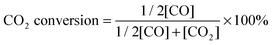 | (4) |
| |  | (5) |
2.3 Electrochemical performance evaluation procedure
During the SOFC test, Au and Pt pastes were painted on the anode and the cathode of the cells, respectively, as the current collectors, which were initially baked in air at 800 °C for 2 h. Pt meshes were used as the secondary current collector on top of those paste, which were connected with Pt wires. The cell was then sealed on the anode side to an alumina tube using a Ceramabond® glass sealant (Aremco Products, Inc.). After the sealant curing, the cell was reduced in H2 at 700 °C for 2 h prior to electrochemical measurements. Open-circuit electrochemical impedance spectra (EIS) and the current density–voltage (I–V) curve were obtained at temperatures ranging from 550 to 700 °C in H2, H2–Ar, H2–CO and CH4–CO2 (molar ratios of the mixed gases were 1:1), the fuel flow rate ranged from 20 mL min−1 to 40 mL min−1. Ambient air (relative humidity = (40 ± 10)%) was used as the oxidant. An impedance/gain phase analyzer (Solartron 1255) and an electrochemical interface (Solartron 1287) were used to record the electrochemical performances. Stability and syngas production tests were carried out via applying a constant current load, and simultaneously monitoring the voltage response as well as the effluent gas composition using a GC. H2 selectivity during the electro-oxidation process was calculated by eqn (6).| |  | (6) |
2.4 Material characterization
All the powder materials were subjected to X-ray diffraction analyses (XRD, Rigaku Rotaflex) for phase identification by using Cu Kα radiation generated at 40 kV and 44 mA. The scan was conducted within a 2θ range between 20° and 80° at a rate of 1° min−1. The NiCo–LDC was further analyzed using a transmission electron microscope (TEM, JEOL 2200 FS). The microstructures of the cells were examined using a scanning electron microscope (SEM, JEOL 6301F). X-ray photoelectron spectroscopy (XPS, Kratos AXIS Ultra) was used to study the surface chemistry of NiCo–LDC powder referenced to the adventitious carbon (C 1s with binding energy = 284.5 eV).
3. Results and discussion
3.1 Conventional state-of-the-art H-SOFC: incapable of efficient internal dry reforming
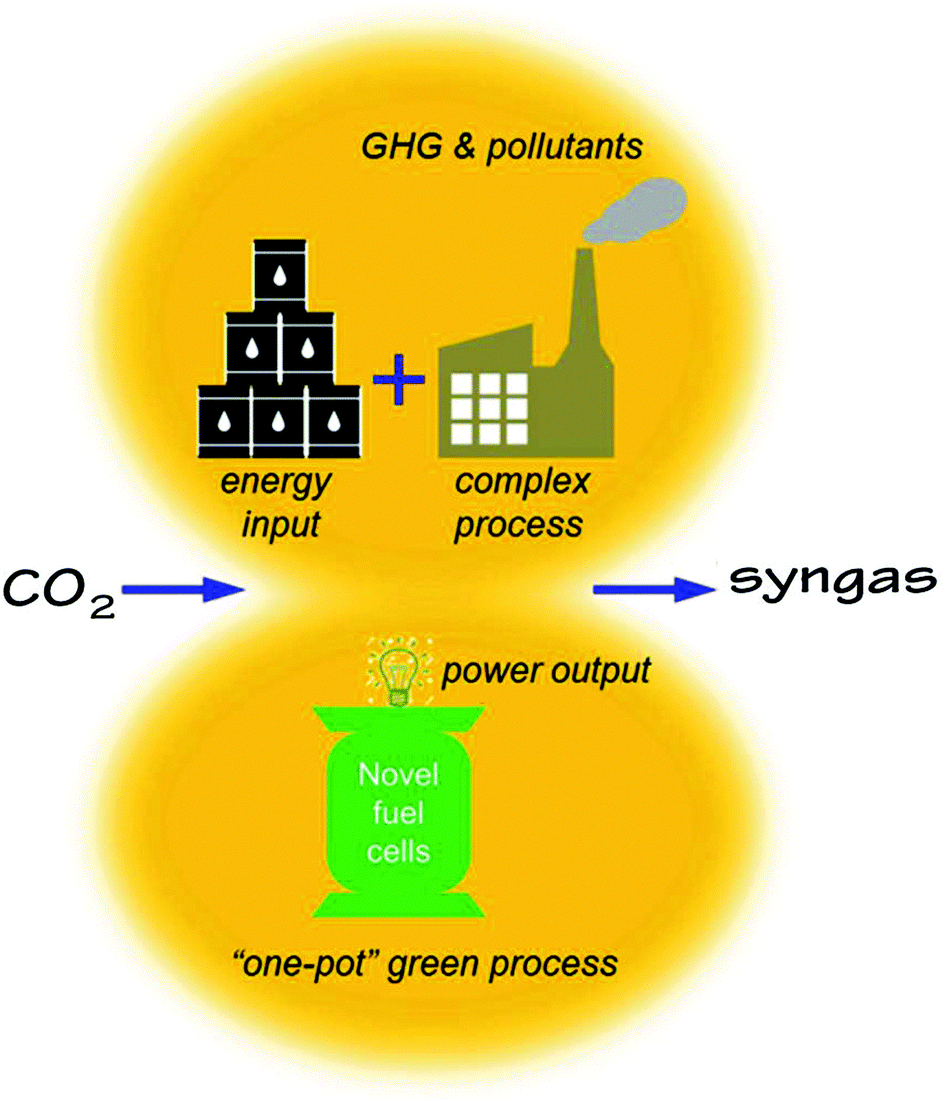
Conventionally, CO2 utilization requires extremely high energy input via complex chemical or electrochemical processes. While producing syngas or other value-added chemicals, the conventional process unfortunately emits additional GHG and pollutants directly or indirectly as shown in Fig. 1. In this work, we propose to use an H-SOFC to achieve a “one-pot” green process for the conversion of CO2, cogenerating power and a CO + H2 mixture that can be used as the feedstock for various chemical syntheses.
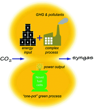 |
| | Fig. 1 A conceptual comparison of the conventional and the proposed novel methods of CO2 utilizations for syngas production. | |
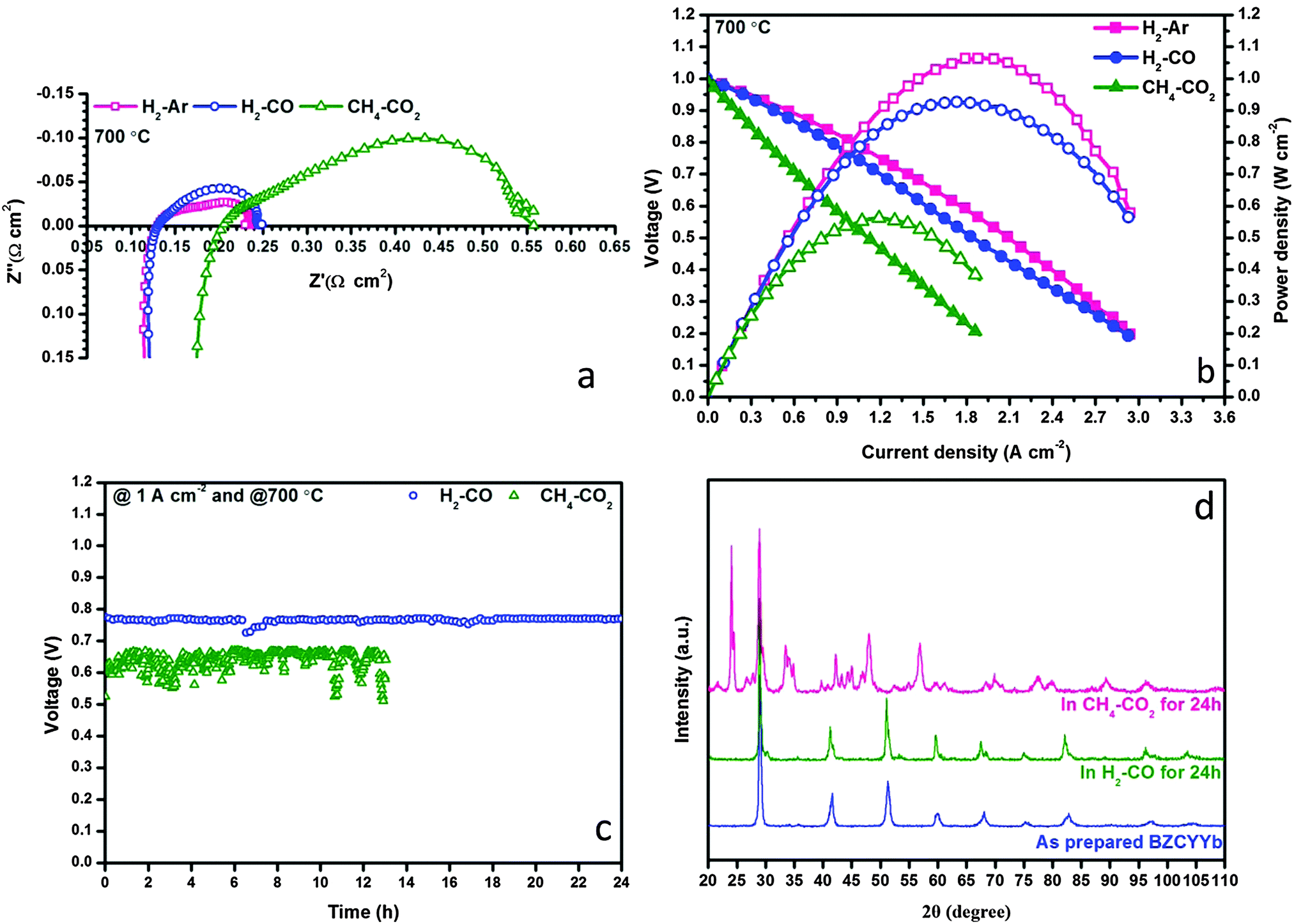
The prepared Ni–BZCYYb/BZCYYb/NBCaC–BZCYYb cell demonstrated superior performances in H2 feedstream, reaching 1480 mW cm−2 maximum power density at 700 °C whereas the polarization resistance (RP) was as low as 0.031 Ω cm2. More details can be found in Fig. S2–S4 in the ESI.† By using this state-of-the-art H-SOFC, we then evaluated its feasibility for the internal dry reforming involving CO2 and CH4. In a control group, fuel cell performance in Ar diluted H2 provides a benchmark to examine the possible negative influences of non-H2 fuels (i.e. CO and CH4) over H2 electrochemical oxidation. Fig. 2a and b show the EIS and I–V(P) curves measured in H2–Ar, H2–CO and CH4–CO2 at 700 °C. The molar ratios of all mixed gases were fixed at 1:1. Remarkably, the RP values of the cell in H2–Ar and H2–CO were essentially identical, 0.106 and 0.112 Ω cm2, respectively, implying that CO did not affect the electrochemical activation and conversion of H2 under this experimental condition. This in turn confirms the potential of using H-SOFC in syngas feedstream. Surprisingly, when CH4–CO2 was used as the fuel, which was supposed to yield syngas with the H2–CO ratio close to unity, the polarization resistance of the cell increased substantially to 0.347 Ω cm2 whereas the ohmic resistance (RO) also grew to 0.201 Ω cm2. Apparently, these results implied that both the physical and the chemical properties of the triple-phase boundary (TPB) have been altered drastically during internal dry reforming. Consequently, the maximum power density dropped to 562 mW cm−2 and the cell suffered from degradations during a 12 h galvanostatic operation at 1 A cm−2.
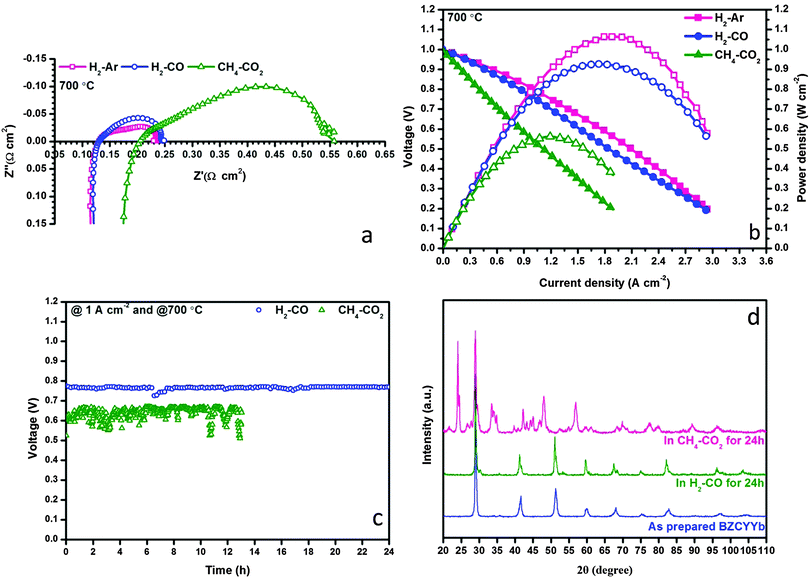 |
| | Fig. 2 Electrochemical performances of conventional H-SOFC in various fuels at 700 °C: (a) impedance spectra, (b) I–V and I–P curves, (c) galvanostatic test at a constant current of 1 A cm−2; and (d) XRD patterns of BZCYYb powder after 24 h exposure to either H2–CO or CH4–CO2 at 700 °C. | |
Thus, it became extremely interesting to understand why the state-of-the-art H-SOFC was incapable of carrying out internal dry reforming. In accordance with the literature, the Ni–BZCYYb composite did exhibit excellent coking resistance in CH4–CO2, rendering few carbon deposits visible on the anode from the SEM observations (Fig. S5 in the ESI†). Coke formation is therefore unlikely to cause the lower performance in CH4–CO2. In the meantime, the ohmic resistance increase shown in Fig. 2a led us to explore if BZCYYb decomposition has occurred despite that Yang et al.20 reported that these materials could be stable in a 50% CO2-containing atmosphere. Our conjecture was proven correct conforming to the impurities appearing in the XRD patterns shown in Fig. 2d. In particular, BZCYYb has reacted with CO2 after the exposure in CH4–CO2 at 700 °C for 24 h forming BaCO3. SEM images in the ESI,† (Fig. S5–S7) also reveal substantial morphological changes of this electrolyte after the designated treatment. Accordingly, we now conclude that the electrochemical performance decrease in CH4–CO2 was ascribed solely to the decomposition of BZCYYb rather than the coke formation. Nevertheless, it is still encouraging to find that BZCYYb based SOFC showed excellent stability in syngas (see Fig. 2c), demonstrating the potentials of fueling H-SOFC with dry reforming derived syngas.
3.2 Multiple-twinned NiCo bimetallic nanoparticles: a superior reforming catalyst
Even in the most advanced H-SOFC discussed above, the low internal reforming efficiency brought a high concentration CO2 stream in the anode causing the deterioration of BZCYYb. This problem makes the direct utilization of CH4–CO2 in H-SOFC challenging. Indeed, the development of a more stable electrolyte can be a straightforward solution,30 but this usually undermines the high proton conductivity of the electrolyte materials. Alternatively, the design of an active dry reforming catalyst compatible with SOFC technology becomes critical.
In an attempt to tackle the obstacles, we herein developed a Ni0.8Co0.2 bimetallic alloy catalyst supported on La doped CeO2 (La0.2Ce0.8O2, LDC) via the GNP method. Although Ni exhibits sufficient catalytic activity towards methane dry reforming, it also fosters severe carbon deposition, leading to catalyst deactivation. Interestingly, alloying Ni with Co could simultaneously improve the catalytic activity while suppressing carbon formation.31,32 Besides, the metal-oxide support interaction might be synergistically boosting the catalytic performance of Ni catalysts.33 We thus tailored a CeO2 support using the La2O3 dopant which stabilized the cubic structure of CeO2 at high temperatures, enhanced the oxygen storage capacity and accelerated CO2 absorption.34
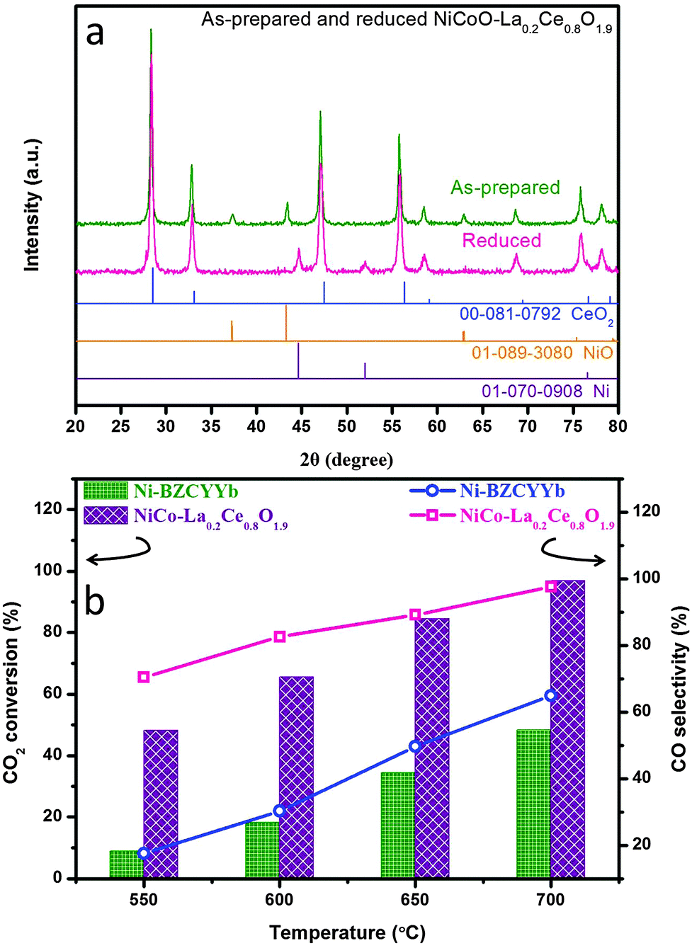
Fig. 3a shows the X-ray diffraction patterns of as-synthesized and reduced NiCoO–LDC, indicating the formations of solid solution in both the metallic and oxide phases. The EDX mappings (Fig. S8 in ESI†) show that the uniform distribution of the bimetallic was obtained in NiCoO–LDC. The dry reforming activity of NiCo–LDC was then compared with Ni–BZCYYb in fixed bed reactors from 550 to 700 °C (Fig. 3b). Noticeably, CO2 conversion increased as a function of temperature for both catalysts. At 700 °C, the conversion over NiCo–LDC reached 96.9% which was more than 2-fold higher than that obtained using Ni–BZCYYb (48.3%). Meanwhile, the corresponding CO selectivity over NiCo–LDC was 97.6%, significantly surpassing that over Ni–BZCYYb (64.9%). The extremely high conversion of CO2 on NiCo–LDC strongly supports its excellence for catalyzing dry reforming reaction.
 |
| | Fig. 3 (a) XRD spectra for as-prepared and reduced NiCoO–LDC; (b) CO2 conversion and CO selectivity comparison using Ni–BZCYYb and NiCo–LDC catalysts in methane dry reforming reaction at temperatures ranging from 550 °C to 700 °C. | |
To further understand the NiCo–LDC catalyst, we initially performed TEM analysis to acquire its compositional and morphological characteristics. Fig. S9 in the ESI,† shows the dark field image of a NiCo–LDC sample and the corresponding EDX elemental mappings of Ni, Co, Ce and La. Apparently, Ni and Co formed bimetallic nanoparticles (NPs) of size 15 to 30 nm and well-dispersed over cube-like LDC crystals. Interestingly, all of the observed bimetallic NPs appeared to have twinned structures that have been proven to possess fascinating catalytic properties.35,36 We then conducted high resolution TEM (HRTEM) analysis to clearly observe the surface structure of the bimetallic NPs. The micrographs in Fig. 4b–d were obtained from the corresponding NPs shown in Fig. 4a. As indicated by the dotted lines in Fig. 4b–d, instead of forming spherical NPs, the NiCo bimetallic NPs had multiple-twinned facets. Stoichiometric amounts of Co and Ni were found on these facets (see Fig. S9 in the ESI†). Possibly, the addition of Co, along with the preparation method, introduced this surface reconstruction stemming from different atomic diffusion rates within the NPs.37 Hence, these well-distributed NPs with multiple-twinned defects can be a key factor pertaining to the high catalytic activity and stability (coking and sintering resistances) of the catalyst.
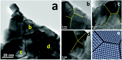 |
| | Fig. 4 TEM analyses of NiCo–LDC catalysts, (a) BF micrograph; (b–d) HRTEM images of NiCo bimetallic nanoparticles at the corresponding sites labeled in (a), the dotted-lines indicate the twin boundaries; and (e) a schematic of a multiple-twinned nanoparticle. | |
In the control group, a catalyst with the same composition was prepared via the wet impregnation method. Although a Ni0.8Co0.2 bimetallic alloy also formed (Fig. S10 in the ESI†), it had different morphologies compared to the GNP counterpart. The spherical NPs suffered from severe agglomerations showing no twinning defects (Fig. S10 and S11 in the ESI†). They thus coherently exhibited much lower activity in dry reforming reactions (Fig. S12 in the ESI†). In addition, more CO2 molecules can adsorb on the catalyst with twinned NPs relative to that obtained using the wet impregnation method (Fig. S13 in the ESI†).
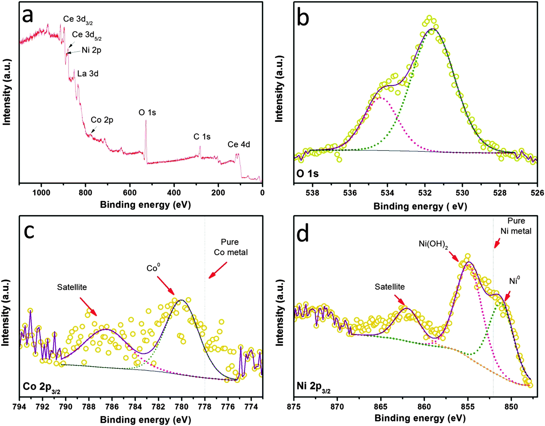
The electronic properties as well as the surface chemistry of the NiCo–LDC hybrid were then studied via XPS measurements shown in Fig. 5. The survey spectrum shown in Fig. 5a confirms the presence of Ni, Co, La and Ce in the sample. The quantitative information from the XPS data reveals that the atomic ratio of Co/Ni is 17.1/82.9, well matching the chemical stoichiometry. Obviously, the surface was hydrated since a strong hydroxyl peak was observed in the O 1s spectrum (Fig. 5b). The spectrum of Ni 2p3/2 shown in Fig. 5d suggests that the surface was (partially) covered by Ni(OH)2. However, these hydroxide shells were unlikely to present under normal SOFC operating conditions. The electronic effect of the bimetallic alloy was determined through studying the Ni0 and Co0 binding energies shown in Fig. 5c and d. Usually, the 2p3/2 orbitals of pure Ni and Co metals have binding energies of ∼852 eV and ∼778 eV, respectively.38–40 When they form an alloy, the Ni0 of NiCo–LDC shifts to a lower binding energy, implying an increased electron density and electronegativity; in contrast, Co0 shifts to a higher binding energy. This electronic structure optimization by alloying was actually an effective way of increasing the catalyst activity towards methane dry reforming.41,42
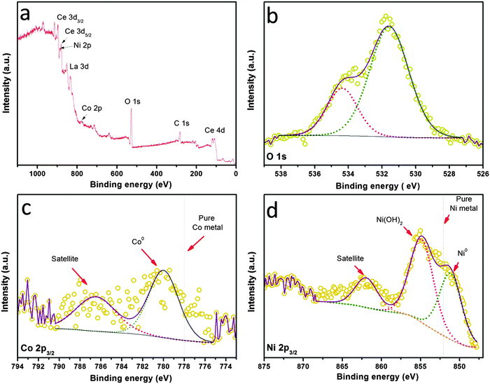 |
| | Fig. 5 XPS spectra of (a) all elements, (b) O 1s, (c) Co 2p, and (d) Ni 2p for the NiCo–LDC powder. | |
3.3 Layered H-SOFC: an ideal single reactor for multi-purposes
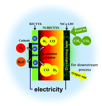
Intuitively, one would imagine that in H-SOFC, if majority of CO2 is converted via methane reforming, the integrity of the BZCYYb electrolyte can be sustained since there is no direct contact between them. Fig. 6 is the schematic illustration of the novel layered SOFC. In this design, an additional reforming layer was incorporated onto the surface of the anode support. The CH4–CO2 feedstream is fully reformed on the high performance NiCo–LDC catalyst layer, yielding syngas, before entering the Ni–BZCYYb functional anode. The sequential selective oxidation of H2 at TPBs not only generates electrical power and CO-enriched syngas, but also provides enough heat completely compensating that required by internal dry reforming. Based on the thermodynamic data shown below, we found that the thermal independency can be acquired when H2 utilization is higher than 52% (corresponding to the total fuel utilization of 26%). This can significantly counterbalance the energy input for conventional methane reforming.| | | CH4(g) + CO2(g) = 2CO(g) + 2H2(g), ΔH = 260 kJ mol−1 (700 °C) | (7) |
| | | 2H2(g) + O2(g) = 2H2O(g), ΔH = −495 kJ mol−1 (700 °C) | (8) |
 |
| | Fig. 6 A schematic showing the configuration of the novel layered H-SOFC. | |
Following this design, we fabricated the layered H-SOFC. Fig. 7a and b show the cross-sectional microstructures of the anode, electrolyte and cathode. The thickness of the dense BZCYYb electrolyte was ∼19 μm whereas that for the NBCaC cathode was ∼25 μm. The porous internal reforming layer is demonstrated in Fig. 7c. No delamination was observed in the interface region, ensuring efficient charge transfer during the cell operation. The EDX mapping results in Fig. 7d also indicate the uniform distribution of NiCo bimetallic NPs across the layer after cell fabrication.
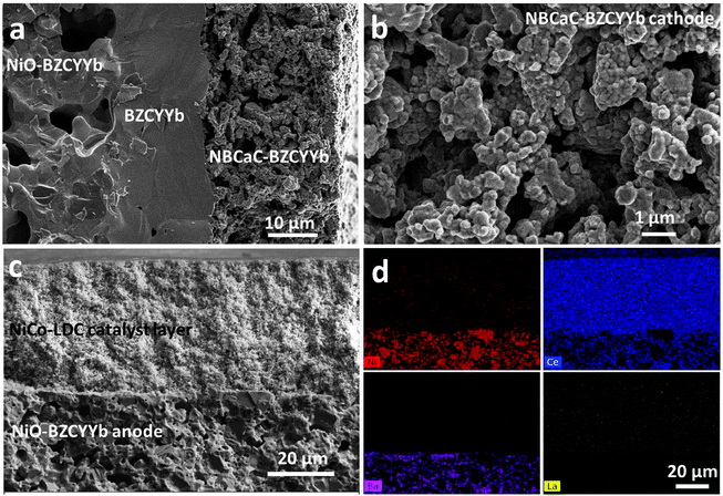 |
| | Fig. 7 Cross-sectional SEM images of layered H-SOFC. (a) Microstructure of the NiO–BZCYYb/BZCYYb/NBCaC–BZCYYb triple layer; (b) magnified image of the NBCaC–BZCYYb cathode; (c) microstructure of the NiCoO–LDC/NiO–BZCYYb interphase; and (d) EDX elemental mappings for (c). | |
The internal dry reforming capability of the layered H-SOFC is compared with that of the conventional counterpart in a stream of CH4–CO2 in Fig. 8a and b. Both the ohmic and the charge transfer resistances were reduced substantially for the layered H-SOFC, simply owing to the improved BZCYYb stability and higher reforming efficiency. Consequently, its maximum power density was up to 910 mW cm−2 at 700 °C. Fig. 8c and d contrast the time-dependent exhaust gas compositions for the conventional and layered H-SOFCs at 700 °C under open circuit voltage (OCV). Not surprisingly, the conventional H-SOFC showed much lower conversions of reactants and poorer stability. After only 6 h, the conversion dropped to below 20%, presumably because of the active site blockage in the anode arising from BZCYYb decomposition products and/or carbon deposition. Conversely, the NiCo–LDC incorporated cell sustained a superior reforming activity after 18 h test, and 90% of CO2 has been reduced.
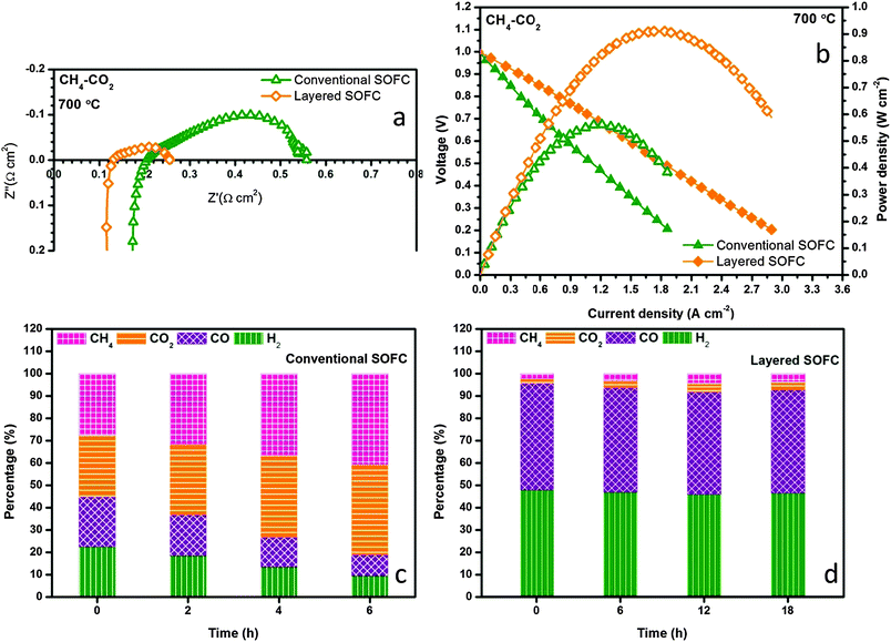 |
| | Fig. 8 Electrochemical performance comparison of conventional and layered SOFCs in CH4–CO2 at 700 °C for (a) impedance spectra and (b) I–V and power density profiles. Time dependent exhaust gas compositions for (c) conventional and (d) the NiCo–LDC incorporated SOFC at OCV and 700 °C when feeding with CH4–CO2. | |
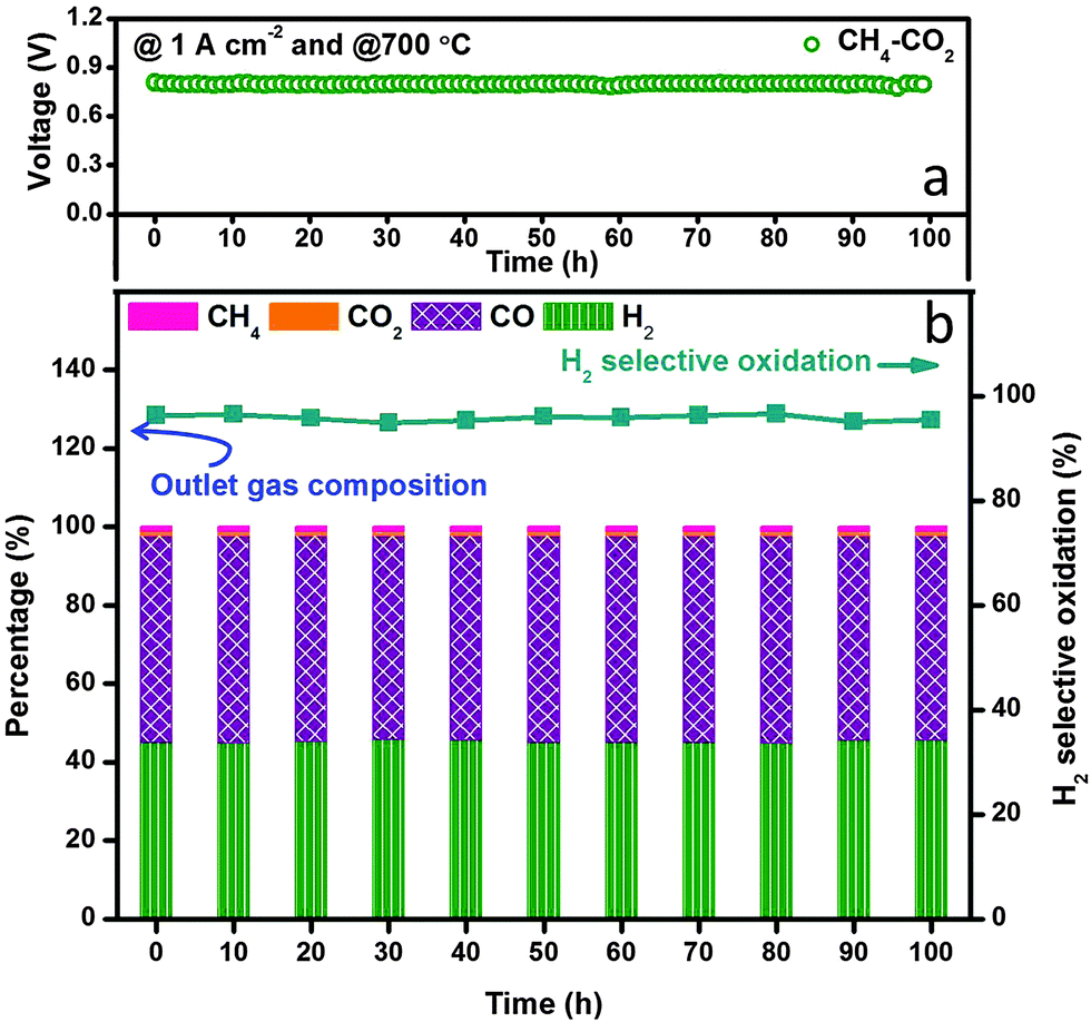
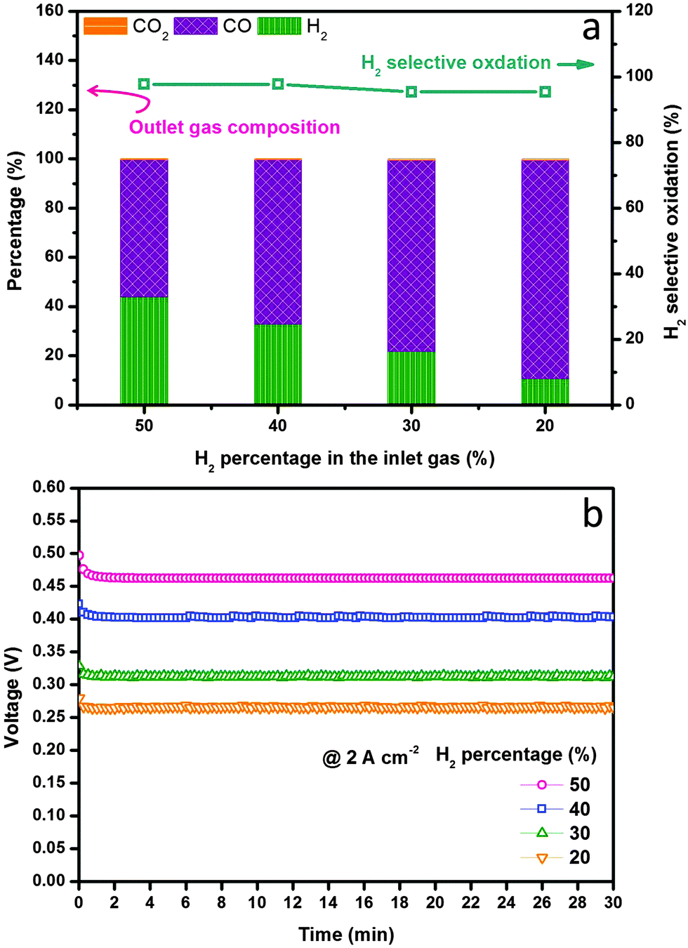
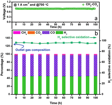
We finally examined the electrochemical stability of the layered H-SOFC for cogenerations of power and chemicals. Fig. 9 displays the long-term performance of the cell under a constant current density load of 1 A cm−2, the voltage stabilized at ∼0.8 V showing negligible degradations, and the power density was as high as 800 mW cm−2. In the meantime, the gas composition of the anode effluent was examined every 10 h using GC. The H2 selectivity stabilized at around 95%, implying that the layered cell was fully capable of accomplishing internal dry reforming in the anode chamber (note that BZCYYb shows some oxygen-ionic conductivity at 700 °C). Thanks to the reforming layer, no microstructure change or carbon depositions were observed in the Ni–BZCYYb anode after 100 h test (Fig. S15, ESI†). Additionally, we explored the adjustment of CO concentration in CO2 derived syngas via electrochemical manipulations in the layered H-SOFC. The practical merit might be compelling: we can use a SOFC reactor to yield syngas with varied H2/CO ratio upon downstream demands. To make the comparison clearer, we used syngas as the feed (without external CH4 and CO2 impurities). Fig. 10a shows H2 selective oxidation in the cell powered by syngas with different H2/CO ratios, in which a constant load of 2 A cm−2 was applied and the anode effluent gas composition was sequentially determined. It can be seen that even when the H2 inlet concentration was as low as 20%, the cell had a voltage of 0.26 V, giving a power density of 520 mW cm−2. After electrochemical oxidation, the H2 concentration was reduced to 10.6% whereas that of CO was enhanced to 88.8%, demonstrating the concept of simultaneously producing CO-enriched syngas using the layered SOFC reactor. Since H2S is a common impurity in natural gas (source of methane), we also studied the sulfur resistance of the SOFC (see Fig. S16 and S17, ESI†). To have a well-defined pH2S/pH2, these tests were performed only in H2S-containning H2. The introduction of 50 ppm H2S (typical concentration43) caused an instant power density drop of the cell. However, during the subsequent galvanostatic measurement, a roughly constant voltage response was recorded, implying it is feasible for practical applications.
 |
| | Fig. 9 Stability test of in situ dry reforming in layered SOFC fuelled with CH4–CO2 at 700 °C. (a) Galvanostatic test under a constant load of 1 A cm−2 and (b) exhaust gas composition records. | |
 |
| | Fig. 10 H2 selective oxidation evaluations at 700 °C in layered SOFC fed with syngas containing various levels of H2. (a) H2 selectivity and the exhaust gas composition as a function of H2 percentage in syngas and (b) the corresponding voltage responses in different feeds under a constant current load of 2 A cm−2. | |
4. Conclusions
The present study demonstrated that the internal dry reforming of methane can be achieved using H-SOFC with a layered structure. The NiCo–LDC internal reforming layer, containing multiple-twinned Ni0.8Co0.2 bimetallic nanoparticles, effectively catalyzed the in situ reforming of methane, avoiding the direct contact of high concentration CO2 with the BZCYYb proton-conducting electrolyte. Hence, the H-SOFC demonstrated excellent electrochemical performances in CH4–CO2 feedstream, coproducing CO-enriched syngas with few CO2 by-products. The present work shed light on the configuration optimizations of SOFC in the context of energy-CO2 conversions.
Acknowledgements
This research was financially supported by the Climate Change and Emissions Management Corporation, Alberta, Canada. N. Yan acknowledges the support from Sustainable Chemistry Research Priority Area of University of Amsterdam (http://www.suschem.uva.nl).
References
- A. Appel, J. Bercaw, A. Bocarsly, H. Dobbek, D. DuBois, M. Dupuis, J. Ferry, E. Fujita, R. Hille, P. Kenis, C. Kerfeld, R. Morris, C. Peden, A. Portis, S. Ragsdale, T. Rauchfuss, J. Reek, L. Seefeldt, R. Thauer and G. Waldrop, Chem. Rev., 2013, 113, 6621–6658 CrossRef CAS PubMed.
- E. L. Muetterties and J. Stein, Chem. Rev., 1979, 79, 479–490 CrossRef CAS.
- C. K. Rofer-DePoorter, Chem. Rev., 1981, 81, 447–474 CrossRef CAS.
- J. Medina-Ramos, J. L. DiMeglio and J. Rosenthal, J. Am. Chem. Soc., 2014, 136, 8361–8367 CrossRef CAS PubMed.
- M. L. Macnaughtan, H. S. Soo and H. Frei, J. Phys. Chem. C, 2014, 118, 7874–7885 CAS.
- C. Costentin, G. Passard, M. Robert and J.-M. Savéant, J. Am. Chem. Soc., 2014, 136, 11821–11829 CrossRef CAS PubMed.
- M. S. Aw, M. Zorko, I. G. Osojnik Črnivec and A. Pintar, Ind. Eng. Chem. Res., 2015, 54, 3775–3787 CrossRef CAS.
- P. Tang, Q. Zhu, Z. Wu and D. Ma, Energy Environ. Sci., 2014, 7, 2580–2591 CAS.
- M. Honda, M. Tamura, K. Nakao, K. Suzuki, Y. Nakagawa and K. Tomishige, ACS Catal., 2014, 4, 1893–1896 CrossRef CAS.
- S. Chan, T. Lam, C. Yang, S. Yan and N. Cheng, Chem. Commun., 2015, 51, 7799–7801 RSC.
- G. Olah, G. Prakash and A. Goeppert, J. Am. Chem. Soc., 2011, 133, 12881–12898 CrossRef CAS PubMed.
- W. Wang, C. Su, Y. Wu, R. Ran and Z. Shao, Chem. Rev., 2013, 113, 8104–8151 CrossRef CAS PubMed.
- S. E. Evans, J. Z. Staniforth, R. J. Darton and R. M. Ormerod, Green Chem., 2014, 16, 4587–4594 RSC.
- K. Lee, C. Gore and E. Wachsman, J. Mater. Chem., 2012, 22, 22405–22408 RSC.
- B. Hua, M. Li, B. Chi and J. Li, J. Mater. Chem. A, 2014, 2, 1150–1158 CAS.
- Z. Zhan and S. A. Barnett, Science, 2005, 308, 844–847 CrossRef CAS PubMed.
- M. Li, B. Hua, S. P. Jiang, J. Pu, B. Chi and J. Li, Int. J. Hydrogen Energy, 2014, 39, 15975–15981 CrossRef CAS.
- B. Hua, M. Li, J. Pu, B. Chi and J. Li, J. Mater. Chem. A, 2014, 2, 12576–12582 CAS.
- M. Li, B. Hua, J. Pu, B. Chi and J. Li, Sci. Rep., 2015, 5, 7667 CrossRef CAS PubMed.
- L. Yang, S. Wang, K. Blinn, M. Liu, Z. Liu and Z. Cheng, Science, 2009, 326, 126–129 CrossRef CAS PubMed.
- C. Zuo, S. Zha, M. Liu, M. Hatano and M. Uchiyama, Adv. Mater., 2006, 18, 3318–3320 CrossRef CAS.
- L. Bi, S. Boulfrad and E. Traversa, Chem. Soc. Rev., 2014, 43, 8255–8270 RSC.
- E. Fabbri, L. Bi, D. Pergolesi and E. Traversa, Energy Environ. Sci., 2011, 4, 4984–4993 CAS.
- E. Fabbri, L. Bi, D. Pergolesi and E. Traversa, Adv. Mater., 2012, 24, 195–208 CrossRef CAS PubMed.
- B. Rainwater, M. Liu and M. Liu, Int. J. Hydrogen Energy, 2012, 37, 18342–18348 CrossRef CAS.
- T. Hibino, A. Hashimoto, M. Suzuki and M. Sano, J. Electrochem. Soc., 2002, 149, A1503–A1508 CrossRef CAS.
- N. Zakowsky, S. Williamson and J. Irvine, Solid State Ionics, 2005, 176, 3019–3026 CrossRef CAS.
- R. Kannan, K. Singh, S. Gill, T. Furstenhaupt and V. Thangadurai, Sci. Rep., 2013, 3, 2138 Search PubMed.
- S. Fang, K. Brinkman and F. Chen, J. Membr. Sci., 2014, 467, 85–92 CrossRef CAS.
- C. Duan, J. Tong, M. Shang, S. Nikodemski, M. Sanders, S. Ricote, A. Almansoori and R. O'Hayre, Science, 2015, 349, 1321–1326 CrossRef CAS PubMed.
- D. San-José-Alonso, J. Juan-Juan, M. Illán-Gómez and M. Román-Martínez, Appl. Catal., A, 2009, 371, 54–59 CrossRef.
- P. Djinović, I. Črnivec, B. Erjavec and A. Pintar, Appl. Catal., B, 2012, 125, 259–270 CrossRef.
- S. Takenaka, H. Ogihara, I. Yamanaka and K. Otsuka, Appl. Catal., A, 2001, 217, 101–110 CrossRef CAS.
- X. Luo, R. Wang, J. Ni, J. Lin, B. Lin, X. Xu and K. Wei, Catal. Lett., 2009, 133, 382–387 CrossRef CAS.
- M. Kumar and S. Deka, ACS Appl. Mater. Interfaces, 2014, 6, 16071–16081 CAS.
- J. Yang, L. Chng, X. Yang, X. Chen and J. Ying, Chem. Commun., 2014, 50, 1141–1143 RSC.
- G. Li, Q. Wang, Y. Cao, J. Du and J. He, Phys. Lett. A, 2012, 376, 534–537 CrossRef CAS.
- K. S. Kim and N. Winograd, Surf. Sci., 1974, 43, 625–643 CrossRef CAS.
- C. Brundle, T. Chuang and D. Rice, Surf. Sci., 1976, 60, 286–300 CrossRef CAS.
- J. Kim, D. Pugmire, D. Battaglia and M. Langell, Appl. Surf. Sci., 2000, 165, 70–84 CrossRef CAS.
- J. Zhang, H. Wang and A. Dalai, J. Catal., 2007, 249, 300–310 CrossRef CAS.
- K. Takanabe, K. Nagaoka, K. Nariai and K. Aika, J. Catal., 2005, 232, 268–275 CrossRef CAS.
- Z. Cheng, J. Wang, Y. Choi, L. Yang, M. Lin and M. Liu, Energy Environ. Sci., 2011, 4, 4380–4409 CAS.
Footnote |
| † Electronic supplementary information (ESI) available. See DOI: 10.1039/c5ee03017j |
|
| This journal is © The Royal Society of Chemistry 2016 |
Click here to see how this site uses Cookies. View our privacy policy here.