
Pressure-retarded osmosis for power generation from salinity gradients: is it viable?
Anthony P.
Straub
,
Akshay
Deshmukh
and
Menachem
Elimelech
*
Department of Chemical and Environmental Engineering, Yale University, P.O. Box 208286, New Haven, Connecticut 06520-8286, USA. E-mail: menachem.elimelech@yale.edu; Fax: +1 (203) 432-4387; Tel: +1 (203) 432-2789
First published on 11th November 2015
Abstract
The enormous potential of harvesting energy from salinity gradients has been discussed for decades, and pressure-retarded osmosis (PRO) is being increasingly investigated as a method to extract this energy. Despite advancements in membranes and system components, questions still remain regarding the overall viability of the PRO process. Here, we review PRO focusing on the net energy extractable and the ultimate feasibility of the most widely explored configurations. We define the maximum energy that can be obtained from the process, quantify losses and energetic costs that will reduce the net extractable energy, and explain how membrane modules can be improved. We then explore the potential of three configurations of PRO: systems designed to control mixing where rivers meet the sea, power plants that utilize the high concentration gradients available from hypersaline solutions, and PRO systems incorporated into reverse osmosis desalination plants to reduce electricity requirements. We conclude by considering the overall outlook of the process and identifying the most pressing challenges for future research.
 Anthony P. Straub | Anthony Straub is a PhD candidate in the Department of Chemical and Environmental Engineering at Yale University. He received his BSc from the University of Illinois at Urbana-Champaign and MSc degree from Yale. He is interested in technologies at the intersection of water and energy, and his research activities focus on the development of emerging membrane-based processes for salinity gradient power, waste heat energy production, and desalination. |
 Akshay Deshmukh | Akshay Deshmukh is a graduate student in the Elimelech Research Group, part of the Department of Chemical and Environmental Engineering at Yale University. Prior to Yale, he completed his BA and MEng in Chemical Engineering at the University of Cambridge. His research interests lie in processes at the water-energy nexus with research activities focusing on the fundamental modelling of reverse osmosis, forward osmosis, and membrane distillation. |
 Menachem Elimelech | Menachem Elimelech is the Roberto Goizueta Professor at the Department of Chemical and Environmental Engineering at Yale University. He received his BSc and MSc degrees from the Hebrew University in Israel and PhD from the Johns Hopkins University in Environmental Engineering in 1989. His research interests are in the areas of emerging technologies at the water energy-nexus, membrane separations for desalination and wastewater reuse, and environmental applications and implications of nanomaterials. |
Broader contextEnergy is released during the spontaneous mixing of two solutions with different salinities. If this mixing energy can be harnessed to generate power, the global potential would be enormous, equal to a significant fraction of the worldwide power demand. Research on methods to extract energy from salinity gradients has grown rapidly, and pressure-retarded osmosis (PRO) has emerged as one of the most promising technologies. While there have been many recent advances in the performance of membranes and other system components for PRO, it is still uncertain whether the process can be feasibly implemented. In this article, we critically review PRO and discuss the amount of energy that can be practically extracted, the overall viability of different envisioned configurations of the process, and critical directions for future research. |
Introduction
Increasing global energy demands and the threat of anthropogenic climate change have revitalized the search for new renewable energy sources.1 Tremendous amounts of energy are available from the spontaneous mixing of different salinity solutions, and harnessing this salinity gradient energy could be a viable source of renewable power.2–4 The power potentially obtainable when the 37![[thin space (1/6-em)]](https://www.rsc.org/images/entities/char_2009.gif) 300 km3 annual global river discharge meets the sea, for example, is estimated to be greater than one terawatt, enough to supply a significant percentage of the global energy demand.5,6 Other more saline sources, such as the Great Salt Lake or the Dead Sea, may also be mixed with low-salinity river water or wastewater effluent for energy production.7,8
300 km3 annual global river discharge meets the sea, for example, is estimated to be greater than one terawatt, enough to supply a significant percentage of the global energy demand.5,6 Other more saline sources, such as the Great Salt Lake or the Dead Sea, may also be mixed with low-salinity river water or wastewater effluent for energy production.7,8
For the energetic potential of salinity gradients to be realized, engineered processes are needed to efficiently convert the available salinity gradient energy to useful work. Several processes have been devised for this task including pressure-retarded osmosis (PRO),9–12 reverse electrodialysis,13–15 capacitive mixing,16,17 and hydrogel swelling.18 The most widely investigated of these processes—PRO—utilizes a semipermeable membrane placed between a low concentration feed solution and a high concentration draw solution.19 The chemical potential difference between the two solutions drives water molecules through the membrane from the feed to the draw solution while solutes are retained. The volume expansion in the draw solution is then restricted to increase the hydraulic pressure of the draw reservoir, and the resulting pressurized flow of water is driven through a hydro turbine to generate power.
Although initially conceived in the 1970s,10 the past decade has seen a resurgence of research on PRO. Major advances have been made in the development of robust membranes tailored for the process,20–24 and models for local mass transfer dynamics have also been greatly improved.21,25–27 Technology development has been emboldened by theoretical studies, which have shown the process is more efficient and cost effective than rival technologies.28,29 In 2009, the Norwegian energy company Statkraft demonstrated the PRO process could be scaled up from the laboratory by constructing the first pilot plant in Norway to harness energy from river water and seawater mixing.30 Subsequently, the Mega-ton project in Japan constructed a pilot PRO system to recover energy from seawater reverse osmosis brine mixing with wastewater effluent.31
Even as PRO appears to be moving beyond nascent stages, questions still remain regarding the overall viability of the process. A major setback for the technology came when Statkraft—the company that pioneered PRO to the pilot level and was planning to construct the first full-scale plant to mix river water and seawater—decided to withdraw all investments from osmotic power.32 Subsequently, theoretical studies posited that it may not be possible for PRO to extract net positive energy from mixing river water and seawater due to the relatively low extractable energy density and the high energetic cost of operation.33,34 Other research has emerged demonstrating practical system limitations and highlighting concerns such as membrane fouling and operational pumping requirements.35–39 Since most PRO studies thus far have focused on membrane fabrication and the mass transfer dynamics of membrane coupons, there is an urgent need to move forward to constructively assess the net efficiency and limitations of the full-scale process. This knowledge is requisite to determine the viability of salinity gradient energy conversion.
We critically review PRO focusing on the net energy extractable from the process and the ultimate feasibility of the most widely explored configurations. We first discuss a framework for the evaluation of PRO systems and the importance of two main performance metrics. Drawing on prior literature, the maximum extractable energy in a PRO system is then quantified and the multitude of inevitable energetic losses are explained. Reducing these losses necessitates membrane modules tailored for the process, and the requirements for these systems are described. We proceed to discuss the overall viability of three envisioned configurations of PRO: power plants situated to control mixing where rivers meet the sea, systems that utilize the high concentration gradients available from hypersaline solutions, and hybrid PRO systems incorporated into reverse osmosis desalination plants to reduce electricity requirements.
Are membrane coupon studies relevant to PRO system performance?
In realistic implementation, PRO will utilize large membrane modules to perform the controlled mixing. However, a majority of experimental PRO studies operate at a much smaller scale, often using results from membrane coupons as if they translate directly to full-scale performance.22,23,26,40 In this section, we discuss the envisioned full-scale PRO process, important performance metrics, and how coupon-scale measurements relate to productivity on a larger scale. The major goal is to emphasize that the ultimate performance of a PRO process can only be predicted by considering a full-scale system.PRO systems will utilize constant-pressure modules
The most widely discussed setup for full-scale PRO is a steady-state, constant-pressure process with energy recovery (Fig. 1A).11,37,41 The high concentration draw solution enters the membrane module after passing through a pressure exchanger (PEX), which increases the operating pressure in the stream to a fixed pressure, ΔP. The low concentration feed stream is pumped into the opposite side of the membrane module at ambient pressure. Driven by the osmotic pressure difference across the membrane, which is greater than the hydraulic pressure difference, water molecules permeate from the feed stream to the draw stream, increasing the flow rate and diluting the pressurized draw stream while decreasing the flow rate and concentrating the feed stream. The exiting pressurized draw stream then bifurcates into a stream that flows through the turbine to generate power and a stream that flows through the PEX where it transfers pressure the incoming draw stream.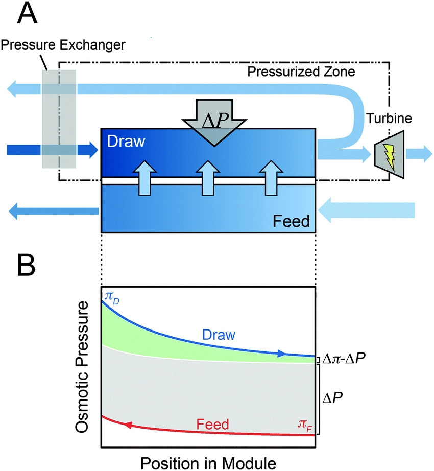 | ||
| Fig. 1 (A) Schematic diagram of a constant-pressure, counter-current PRO system with energy recovery from a pressure exchanger. Darker colors correspond to a higher salinity and the thickness of each arrow denotes the relative flow rate. (B) Osmotic pressure profiles of the draw (blue line) and feed (red line) solutions along the length of a membrane module. The initial osmotic pressures of the draw and feed solutions are πD and πF, respectively. At any point in the module, the driving force for permeation available from the solutions is the difference between the osmotic pressure of the draw and feed, Δπ. The hydraulic pressure difference, ΔP, reduces the driving force (gray shaded region), resulting in a net driving force of Δπ − ΔP at any point in the module (green shaded region). | ||
The power generated in the system is equal to the flow rate through the turbine multiplied by the hydraulic pressure difference, ΔP.33 Since the PEX requires approximately equal flow rates on either side, the flow rate into the turbine is equal to the flow rate across the membrane, ΔQ, and the power output is ΔQΔP.
Specific energy and power density quantify system performance
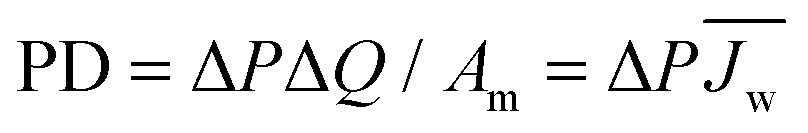
When discussing the productivity of any system, relevant performance metrics must be defined. The major aim of a PRO process is to economically extract a suitable amount of power.10,42 Towards this goal, studies have predominantly focused on two performance metrics which relate to the energy efficiency and utilization of membrane area.19,43 These metrics are useful in that they can be determined from experimental data and enable the estimation of system cost.The first performance metric is the power density (PD), which defines the amount of power that can be extracted per unit of membrane area in the system.26,44 Increasing the power density will enable high power output systems with low membrane area, a crucial factor since membranes will be one of the largest capital costs and membrane replacement will constitute a significant operating cost.29,45 The power density of a module, PD, can be calculated by dividing system power output, ΔQΔP, by the membrane area, Am:
 | (1) |
 , multiplied by the hydraulic pressure difference.
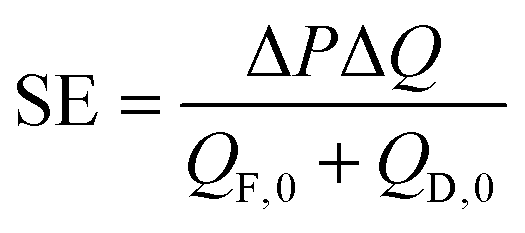
A second performance metric is the specific energy (SE) extractable from the system.33,34 The specific energy quantifies how much energy can be extracted per unit volume of initial draw and feed solution used. It can be calculated by dividing the power output, ΔQΔP, by sum of the initial feed flow rate, QF,0, and initial draw flow rate, QD,0:
 | (2) |
We note that the power density and specific energy are simply methods of normalizing the power output of the system, ΔQΔP. Other normalization methods have also been used in studies for various purposes.46–50 However, the two metrics defined above are well-established in the literature and useful for comparison and optimization.
High coupon-scale power densities are not indicative of increased full-scale system efficiency
A common point of confusion in PRO literature is the transferability of results from coupon-scale system testing to full-scale system performance. Understanding the difference between the two scenarios requires consideration of behavior in the membrane module. In realistic membrane modules, the water permeating across the membrane will cause variations in the concentration and flow rate along the draw and feed channels.33 Since high permeation flow rate across the membrane, ΔQ, is needed to maximize the efficiency of the system, substantial changes in concentration and flow rate will be necessary.Fig. 1B illustrates the changes in osmotic pressure that will occur throughout a membrane module in counter-current flow. The draw solution will be diluted by the permeating water, lowering the osmotic pressure, and the feed solution will be concentrated. The driving force available for permeation at any point in the module is manifested in the osmotic pressure difference, Δπ, which will be reduced by the hydraulic pressure difference, ΔP, resulting in a net driving force of Δπ − ΔP.51,52 From Fig. 1B, it is apparent that the net driving force at any position in the module will never be equivalent to that available from the initial bulk draw and feed solutions because of the dilution and concentration that occurs in the draw and feed streams, respectively.34
A majority of PRO studies are performed using small-scale membrane coupons and, because only a small amount of water can permeate across the membrane, the osmotic pressure is effectively fixed on either side of the membrane coupon. In most experiments, these osmotic pressures are set at the initial bulk values of the feed and draw solutions. As can be seen in Fig. 1B, a realistic membrane module would never experience such a large driving force. Hence, water flux measurements and power density estimates from these coupon-scale experiments are much higher than those that would occur in full-scale systems. For example, a current commercial membrane operating with model seawater as a draw solution (0.6 M NaCl) and river water as a feed solution (0.015 M NaCl) can achieve a power density of approximately 6.2 W m−2 in coupon-scale testing, assuming power density is calculated by multiplying the water flux, Jw, by the hydraulic pressure difference, i.e., PD = JwΔP.34 However, since the small-scale test system has a very low membrane area, the two solutions are hardly mixed and a nearly negligible percentage of the total energy available from the draw and feed solutions is extracted. To reach a reasonable efficiency of energy extraction with the membrane, such as 80% of the maximum achievable specific energy, the system would operate at a power density of only 2.7 W m−2.34
Since there is a substantially lower localized driving force in membrane modules compared to coupon-scale test cells, meaningful power densities cannot be calculated by simply multiplying coupon-scale water fluxes by the hydraulic pressure difference. This calculation method would lead to a dramatic overestimation of the power density because it neglects the substantial decrease in driving force that will be required in an efficient membrane module. Similarly, the threshold of achieving a power density greater than 5 W m−2 has been discussed as a requirement for the economic viability of a river water and seawater system.9,41 However, studies applying this threshold have largely ignored the consideration of system efficiency, and that power densities calculated from coupon-scale tests would not translate to a larger system. Thus, experimental work striving to simply improve coupon-scale power density measurements is not inherently useful in pushing forward PRO technology. Instead, experimental measurements are more valuable if thorough characterization techniques are used to determine transferable membrane properties that maintain relevance to large-scale operation. Later, we will discuss suitable system performance parameters that can be determined in the laboratory and also further describe the relationship between power density, specific energy, and system viability.
What is the maximum energy extractable?
The Gibbs energy of mixing is the theoretical upper limit of extractable energy
Understanding the maximum energy extractable from a PRO system is necessary to determine the theoretical potential of various sources and a starting point for identifying whether salinity gradient energy is viable. The maximum specific energy is obtained in a thermodynamically reversible system, which can be envisioned as a variable-pressure batch process where the feed and draw solutions are separated by a perfectly selective semipermeable membrane.46 At the start of the process, the applied hydraulic pressure across the membrane is equal to the osmotic pressure difference (ΔP = Δπ) and no flow permeates across the membrane. The hydraulic pressure is then decreased infinitesimally to allow a small amount of water to permeate across the membrane from the feed to the draw. The permeating water dilutes the draw solution slightly and concentrates the feed solution, decreasing the osmotic pressure difference to bring the system back to equilibrium. The decrease in hydraulic pressure is continued for an infinite number of steps until the hydraulic pressure difference reaches zero and the two solutions have completely mixed.It has been shown that the energy available from the reversible PRO process exactly equals the Gibbs free energy of mixing, ΔG.46 The Gibbs free energy therefore provides a useful upper limit to system performance, where a realistic system will always extract less than this value. A simple equation to determine the Gibbs free energy of mixing per volume of total feed and draw solution has been derived assuming ideal solutions (i.e., activity coefficients are unity and solutes negligibly contribute to volume):33,53
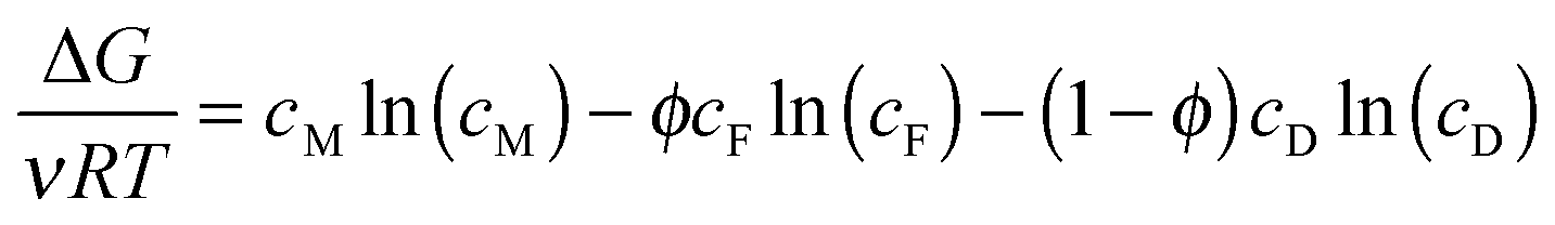 | (3) |
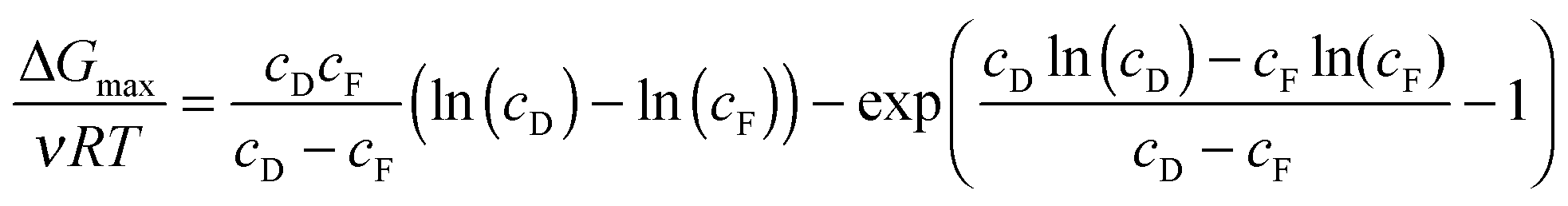
The maximum Gibbs free energy of mixing for a given concentration pairing can be determined analytically by optimizing the feed fraction, ϕ:33
 | (4) |
The maximum Gibbs free energy of mixing is shown in Fig. 2 as a function of the draw NaCl concentration for a feed solution concentration of 0.015 M NaCl, the approximate salinity of river water or wastewater effluent. The specific energy increases from 0.26 kW h m−3 for a seawater draw solution (∼0.6 M NaCl) to around 2.52 kW h m−3 for hypersaline water from the Dead Sea. The maximum Gibbs free energy of mixing for seawater reverse osmosis desalination brine (∼1.2 M NaCl, assuming 50% recovery) is approximately 0.55 kW h m−3.
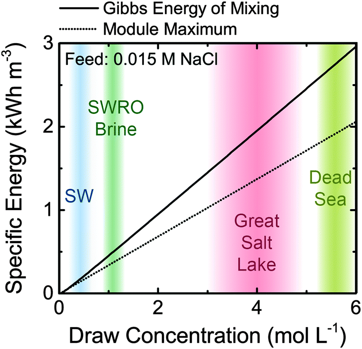 | ||
| Fig. 2 Specific energy extractable in a system as a function of draw solution molar concentration (NaCl equivalent). The feed solution is 0.015 M NaCl, an approximate salinity for river water or wastewater effluent. Specific energy is defined as the energy extractable per total volume of initial feed and draw solutions. The maximum possible specific energy extractable, equal to the Gibbs free energy of mixing, is shown (solid line) alongside the practical limit of extractable energy from a constant-pressure, counter-current PRO membrane module (dotted line). Also indicated are the approximate salinities of various potential draw solutions: seawater (SW), seawater reverse osmosis (SWRO) desalination brine, Great Salt Lake water, and water from the Dead Sea. The temperature is assumed to be 25 °C. | ||
Constant-pressure operation will reduce the extractable energy
The reversible PRO process is useful to determine the thermodynamic upper limit of specific energy extractable. However, full-scale PRO systems will operate in continuous, constant-pressure modules that have additional constraints on the extractable energy from the system.46 As was discussed in the previous section, the osmotic pressure of the feed and draw solutions will vary along the length of a membrane module as water permeates across the membrane (Fig. 1). Increased permeation flow across the membrane, and hence larger changes in the osmotic pressure along the module will maximize the specific energy extracted (eqn (2)). However, the osmotic pressure difference between the draw and feed solutions, Δπ, at any position in the module can never be lower than the hydraulic pressure difference, ΔP.33 This means that the constant-pressure requirement places a limit on the permeation flow rate, ΔQ, that can occur across the membrane module. At the theoretical limit of operation—when the membrane area is infinitely large—the condition where Δπ is equal to ΔP (i.e., no driving force for permeation) will occur at one or both sides of the module.33The most efficient constant-pressure membrane module will operate with counter-current flow and, at any point in the module, the osmotic pressure difference, Δπ, will be infinitesimally larger than the hydraulic pressure difference, ΔP.33,47 At this limit, the draw solution will always exit the module at an osmotic pressure equal to the sum of the initial feed osmotic pressure and the hydraulic operating pressure. Similarly, the feed solution will exit the module at an osmotic pressure equal to the initial draw osmotic pressure subtracted by the hydraulic operating pressure. To reach these conditions, the feed flow rate fraction, ϕ, and the applied hydraulic pressure, ΔP, must be optimized. Previous work has found that the optimal feed flow rate fraction, ϕ, is one-half, so equal flow rates of feed and draw solution are used. The optimal applied hydraulic pressure at this feed flow rate fraction in an ideal system is equal to half the initial osmotic pressure difference.33,35 Using these conditions, the theoretical limit extractable energy in a constant-pressure, counter-current membrane module can be determined:33
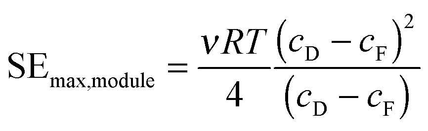 | (5) |
It is important to note that to obtain the maximum extractable energy in a constant-pressure module, very large membrane areas will be necessary and the power density will approach zero (eqn (1)). Thus, the desire for high efficiencies will have to be balanced with the need to reduce the membrane area in the system.34 The specific energy in eqn (5) also does not account for many substantial losses and energetic costs of system operation. In the following sections, we will discuss and quantify these values to refine our estimate of the net specific energy extractable from a PRO system.
What is required of PRO membranes and modules?
Realistic membrane modules will have a multitude of losses that will reduce the amount of energy that can be extracted. In this section, the performance-limiting phenomena of concentration polarization, reverse salt flux, and membrane fouling are discussed. We introduce key membrane performance parameters and highlight the optimal membrane characteristics to maximize both power density and specific energy. Possible energetic costs for pumping in modules and pretreatment are also quantified.Low structural parameter without compromised mechanical integrity
The water flux across the membrane, Jw, can be defined in terms of the membrane water permeability coefficient, A; the osmotic pressure at the draw side of the membrane active layer, πD,m; the osmotic pressure at the feed side of the membrane active layer, πF,m; and the hydraulic pressure difference across the membrane, ΔP:54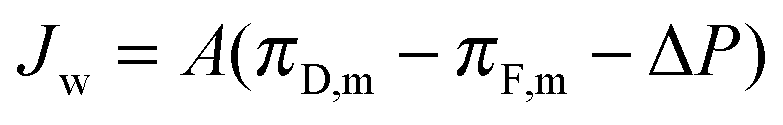 | (6) |
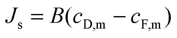
Similarly, the reverse salt flux across the membrane, Js can defined as a function of the salt permeability coefficient, B; the concentration at the draw side of the membrane active layer, cD,m; and the concentration at the feed side of the active layer, cF,m:55
 | (7) |
Concentration polarization in the boundary layers on both sides of the membrane will reduce osmotic pressure difference across the membrane as compared to that available from the bulk feed and draw solutions, limiting the water flux achievable in the process.21,56–58 As water molecules permeate across the membrane from the feed to the draw solution, rejected solutes build up on the feed side of the membrane active layer. Simultaneously, the concentration at the draw side of the membrane active layer is diluted by the permeating water. Diffusion works to counteract these advection effects. However, the net result is a dramatic reduction in the osmotic pressure difference at the active layer, as represented schematically in Fig. 3.
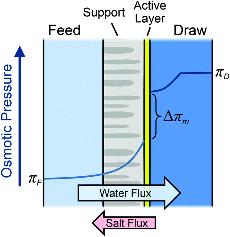 | ||
| Fig. 3 Schematic diagram of the membrane channel cross section. The directions of water flux and reverse salt flux are indicated. The approximate osmotic pressure profiles along the thickness of the channel are also shown where πF is the bulk feed osmotic pressure, πD is the bulk draw osmotic pressure, and Δπm is the osmotic pressure difference across the membrane active layer. | ||
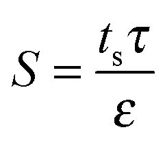
On the feed side of the membrane, the support layer limits hydrodynamic mixing causing severe internal concentration polarization (ICP) within the unstirred porous support.56,58 The effect of internal concentration polarization is quantified using the structural parameter of the support layer (S), which is dependent on the support layer thickness (ts), tortuosity (τ), and porosity (ε):
 | (8) |
Numerous studies have worked to decrease the structural parameter of membranes by tailoring the support layer structure and chemistry, reaching values lower than 500 μm.20,22,24,59 However, since PRO membranes are subject to high hydraulic pressures, membranes must be optimized to have suitably low structural parameters while still maintaining sufficient mechanical integrity to prevent rupture during operation. Thin custom-made membranes with very low structural parameters around 140 μm have been shown to withstand pressures up to 15.2 bar,22 while thicker membranes with structural parameters around 700 μm can operate at up to 55.2 bar applied hydraulic pressure.60 Relations between structural integrity and performance will be further discussed later in the review.
High ECP mass transfer coefficient with low pumping losses
In PRO, concentration boundary layers will also form outside the membrane in a phenomenon referred to as external concentration polarization (ECP).61 ECP can be minimized by improving the hydrodynamics at the membrane–solution interface. For example, increasing the crossflow velocity or inducing additional turbulence using a spacer can curtail ECP. However, enhancing the hydrodynamic conditions will inevitably require greater pumping energy due to increased frictional losses in the channel. Reducing ECP is therefore only worthwhile if the improvement in performance offsets the additional pumping requirements leading to a net positive productivity gain.Dilutive ECP on the draw side of the membrane is the most widely considered form of ECP in PRO.21,61 Since any dilution will affect the large draw solution concentration, the driving force will decrease substantially due to ECP. Dilutive ECP is typically quantified using the draw mass transfer coefficient, k, which must be maximized for the best performance without incurring a substantial pressure drop along the draw channel. In spiral-wound PRO membrane modules operating with suitable hydrodynamic conditions, the pressure drop across the draw channel during operation has been measured as approximately 0.8 bar per meter length of module.37
ECP on the feed side of the membrane is difficult to quantify and typically ignored since feed side mass transfer resistance is dominated by ICP.62–64 However, past studies have noted that water flux across a membrane suffers if the crossflow rate in the feed channel is decreased beyond a certain point, indicating that ECP on the feed side can impact performance.27,60,65,66 Additionally, since the membrane feed channel in spiral wound modules is densely packed with spacers, the pressure drop in the feed channel can be large, even at low crossflow velocities. The pressure loss in a spacer-filled feed channel has been found to range between 2 and 5 bar m−1, depending on the operating conditions.37,60
High selectivity to minimize uncontrolled mixing from reverse salt flux
Current semipermeable membranes cannot perfectly reject solutes, and reverse solute permeation from the high concentration draw solution to the feed solution will inevitably occur (eqn (7)). Reverse solute flux is detrimental to system performance through two predominant mechanisms. First, reverse salt flux will exacerbate the negative effect of concentration polarization, reducing the water flux achievable in the system.61 When solutes are transported from the draw to the feed stream, the concentration at the draw side of the active layer will be diluted and the concentration at the feed side of the active layer will be increased, thereby diminishing the driving force available. Second, in module-scale systems, reverse salt flux will detrimentally change the bulk concentrations of the feed and draw streams.24,34 For example, as water moves along the feed channel, the concentration in the bulk will increase further down the module as more solutes have built up. This uncontrolled mixing will lower the energy extractable from a full-scale system.The reverse salt flux selectivity—defined as the flux of water permeated divided by the reverse solute flux Jw/Js—is a common parameter to quantify salt leakage in osmotically-driven membrane processes. Higher reverse salt flux selectivity values are favorable as they indicate an increased preference to transport water across the membrane than salt. However, the selectivity will be reduced in PRO when hydraulic pressure is used during operation.67 This is because the hydraulic pressure difference retards the water flux across the membrane (eqn (6)), but does not directly affect the reverse salt flux, which is only dependent on the concentration difference (eqn (7)). Therefore, as compared to an unpressurized process like FO, PRO suffers from increased salt passage per water volume permeated.
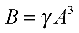
Past studies have aimed to increase the selectivity of the membranes to reduce the effect of reverse salt flux.68–70 A major improvement was realized when osmotic membranes transitioned from cellulose acetate active layers to polyamide active layers, which have superior salt rejection.68,71,72 However, the selectivity of polymeric membranes is constrained by the water permeability-solute selectivity trade-off, which stipulates that any improvement in water permeability will be met with concomitant increase in solute permeability.61,73,74 This trade-off is hypothesized to be an inherent limitation of polymeric membranes, since separation relies on the preferential partitioning and diffusion of smaller water molecules compared to larger hydrated salt ions. The water permeability coefficient, A, and salt permeability coefficient, B, of polymeric membranes are empirically related using the following equation:61,73
 | (9) |
Optimized membrane properties for improved performance
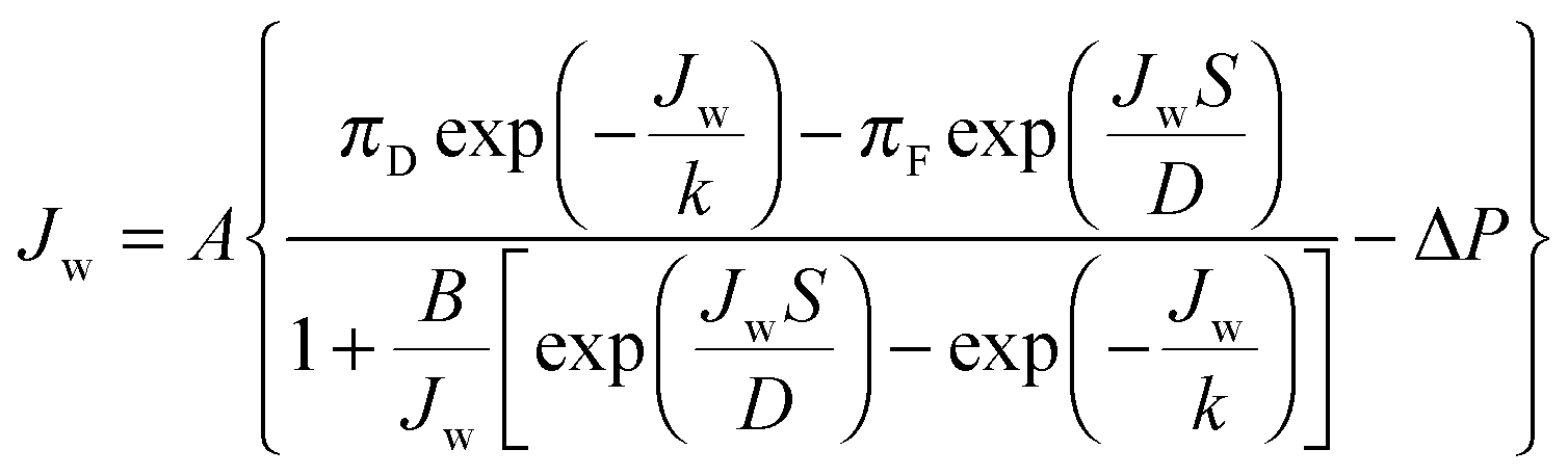
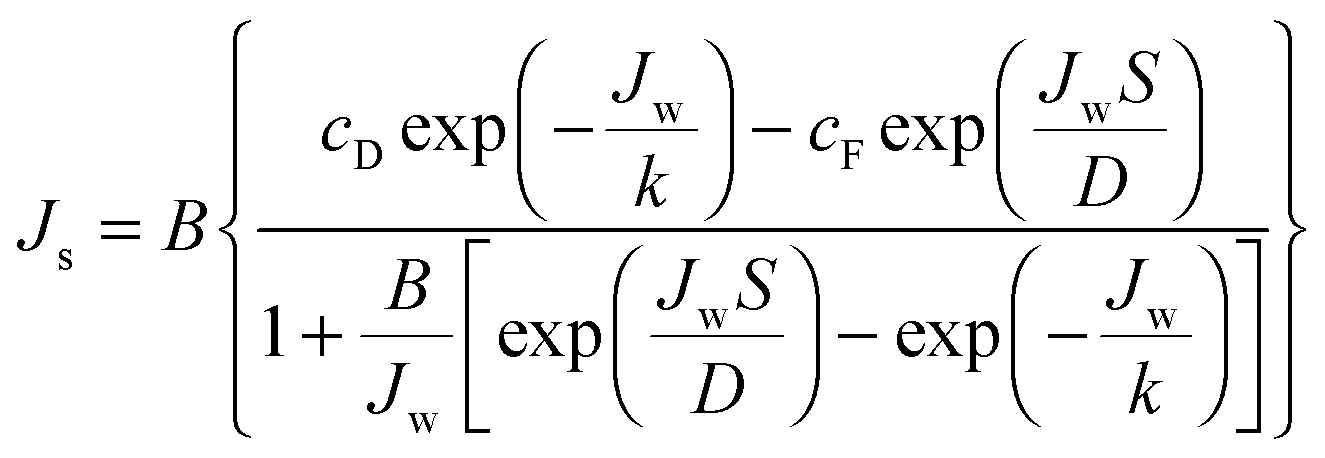
Based on film theory, equations have been developed to determine the concentration at either side of the membrane with reverse salt flux and concentration polarization accounted for:21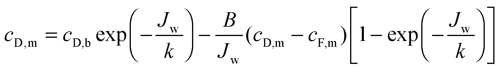 | (10) |
 | (11) |
 | (12) |
 | (13) |
Utilizing the above equations, it is possible to understand the relative importance of different membrane characteristics. Fig. 4A shows the coupon-scale membrane water flux with varying membrane active layer and support layer properties. The water permeability and salt permeability in the figure are linked by the permeability-selectivity trade-off (eqn (9)). It is straightforward that a lower support layer structural parameter will always result in a higher water flux by reducing internal concentration polarization. However, the active layer water permeability cannot simply be increased to improve performance since, after a certain point, the negative impact of reverse salt flux will outweigh the positive impact of a higher water permeability. Even with a perfectly selective membrane, increasing the water permeability coefficient of the membrane beyond a certain threshold will not offer substantial performance improvements, since the higher water flux will be met with exacerbated concentration polarization.
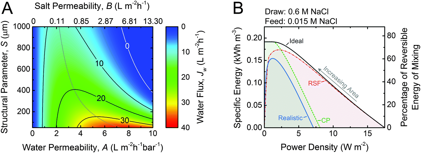 | ||
| Fig. 4 (A) Coupon-scale water flux as a function of the water permeability coefficient, A; NaCl permeability coefficient, B; and support layer structural parameter, S. The water permeability and salt permeability are linked by the permeability-selectivity trade-off (eqn (9)). The dotted gray line represents the active layer properties that maximize the water flux with a given structural parameter. A draw mass transfer coefficient, k, of 38.5 μm s−1 (138.6 L m−2 h−1) is used. (B) Specific energy and power density for counter-current membrane modules with increasing membrane area from right to left. Data for three types of membranes are shown: ideal (solid black line) refers to a membrane with no concentration polarization, no reverse salt flux, and a water permeability coefficient, A, of 3 L m−2 h−1 bar−1; RSF (dash dotted red line) denotes a membrane with reverse salt flux (B = 0.36 L m−2 h−1 according to eqn (9)) and no concentration polarization; CP (dashed green line) indicates a membrane with concentration polarization (S = 500 μm and k = 38.5 μm s−1) and no reverse salt flux; and realistic (solid blue line) refers to a membrane with both reverse salt flux and concentration polarization accounted for. Equal initial flow rates of feed and draw solutions are used. For both figures, the draw concentration is 0.6 M NaCl (seawater) and the feed concentration is 0.015 (river water) and the applied hydraulic pressure is 14.5 bar. | ||
While the coupon-scale water flux calculations in Fig. 4A are useful to understand the localized fluxes, full-scale modeling must be used to identify the importance of concentration polarization and reverse salt flux on system performance.34,45,47,75Fig. 4B shows the specific energy extracted from a module as a function of the power density for a seawater (0.6 M NaCl) and river water (0.015 M NaCl) solution pairing. To produce each curve, the performance of many different PRO modules with increasing membrane area is modeled.34 The ideal curve (black line) is representative of a membrane with no reverse salt flux or concentration polarization and a water permeability coefficient, A, of 3 L m−2 h−1 bar−1. At very low membrane areas, similar to those that would be used in coupon-scale tests, the power density is high and the specific energy extracted is low because a miniscule extent of mixing has occurred. As the membrane area is increased, the feed solution is concentrated and the draw solution is diluted, diminishing the localized driving force for permeation and the power density. However, the concentration changes and driving force reduction throughout the module are an inevitable consequence of the energy extraction required to harvest a high specific energy. At the highest membrane area, the system extracts the theoretical maximum possible energy, equal to 0.192 kW h m−3 (eqn (5)), but also has a power density of almost zero. This inherent trade-off between power density and specific energy, discussed in the first section of this article, will occur in any membrane module and requires appropriate prioritization.
The introduction of realistic effects in the membrane module dramatically alters the behavior of the specific energy vs. power density curve.34 Theoretical membranes with reverse salt flux but not concentration polarization (red dash dotted line) will perform similarly to ideal membranes at low membrane areas. However, as the membrane area increases, the specific energy and power density extractable are lower than the ideal case. The loss in performance is due to a greater extent of uncontrolled mixing as the membrane area increases resulting in more considerable changes to the bulk feed and draw concentrations. Eventually, larger membrane areas will actually result in lower extractable energy, since any gain in water permeation across the membrane is met with a more substantial detrimental effect from reverse salt flux.
When concentration polarization is accounted for in a membrane with perfect selectivity (green dashed line), a nearly opposite trend is observed. With low membrane areas, the detrimental effect of concentration polarization on the power density is very pronounced since concentration polarization affects the large localized driving force available. As the membrane area increases, however, the curve begins to match the performance of an ideal membrane. This observation is quite intuitive since concentration polarization is dependent on the water flux across the membrane (eqn (10) and (11)). At lower power densities the water flux will be lower, and eventually the effect of concentration polarization will be negligible.
When the realistic effects of concentration polarization and reverse salt flux are simultaneously considered, they synergistically decrease both the specific energy and the power density in a membrane module. At very low membrane areas, reverse salt flux exacerbates concentration polarization, thereby decreasing the power density. At higher membrane areas, concentration polarization will worsen the uncontrolled mixing from reverse salt flux and reduce the specific energy.
Overall, the data in Fig. 4B emphasizes the need to reduce both reverse salt flux and concentration polarization in the membrane module. They also reinforce that coupon-scale power densities (corresponding to the bottom x-axis) are not representative of the performance of the module as a whole. In particular, reverse salt flux can have a dramatic effect on the full-scale specific energy and power density that is not well-represented from observations in coupon-scale testing. Therefore, when reporting laboratory performance, calculating the membrane properties (A, B, and S) using well-established methods is much more insightful than simply reporting water fluxes or salt fluxes.21,60,76,77
Membranes and spacers designed to reduce fouling
The sources of water used in PRO will inevitably contain inorganic, organic, and microbial constituents that deposit on and adsorb to the membrane surface.39,78–80 Since the membrane is oriented with the porous support layer facing the feed solution, foulants in the feed will accumulate within the membrane support layer, where they are difficult to remove by simply increasing shear forces.81 As a fouling layer builds up in the support layer of the membrane, hydraulic resistance and concentration polarization increase, leading to diminished performance.The detrimental effect of membrane orientation in PRO on fouling has been shown clearly in experimental studies (Fig. 5A).81,82 With the active layer oriented facing the feed solution (i.e., forward osmosis mode), a less than a 5% flux decline was observed using humic acid and 20 nm silica particles as model organic and inorganic foulants, respectively.82 However, when the membrane orientation is reversed so the support layer faces the feed solution, as will occur in PRO, the water flux decline with the same initial flux was greater than 30%. This increased flux decline in PRO has been attributed to foulants in the feed stream being continuously carried into the thick and porous membrane support layer.
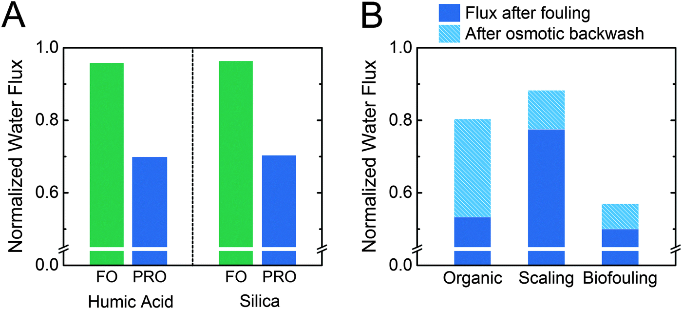 | ||
| Fig. 5 (A) Flux after fouling for asymmetric cellulose triacetate membranes oriented in either FO or PRO modes. Humic acid or 20 nm silica particles were used as model foulants, and the system was operated without applied pressure.82 (B) Flux after fouling and flux recovery from an osmotic backwash for membranes oriented in PRO mode only (i.e., support layer facing the feed solution). Organic fouling was conducted with Suwannee River natural organic matter in unpressurized operation with thin-film composite membranes.38 Scaling experiments were conducted with a model wastewater salinity feed solution, cellulose triacetate membranes, and pressure-aided osmotic backwashing at 10 bar.83 Biofouling experiments were conducted with Pseudomonas aeruginosa bacteria in model wastewater effluent with thin-film composite membranes operated at a hydraulic pressure of 26.2 bar.78 | ||
The relatively high fouling propensity in PRO is worsened by a low fouling reversibility. In lab-scale PRO experiments, cleaning is typically performed using osmotic backwashing, where the feed and draw solution concentrations are exchanged so water permeation across the membrane reverses, pulling foulants away from the membrane support layer. Water flux recovery after osmotic backwashing ranges from 14% to 58% for organic, inorganic, and biological foulants (Fig. 4B).38,78,83 Fouling reversibility was found to be particularly low for biological fouling, with a flux recovery of only 14%.78 In contrast, forward osmosis (FO) can recover 80–100% of the initial flux after simply flushing with an increased crossflow velocity.81,84,85 The low fouling reversibly in PRO can be attributed to the membrane orientation, which causes foulants to remain trapped in the porous support structure.
An additional consideration is the effect of fouling on pressure drop in a spacer-filled feed channel. Fabric feed spacers are particularly well-suited to support flat sheet membranes under pressure and minimize pressure drop.86,87 However, these thick spacers are also prone to clogging if the feed solution is contaminated by foulants. A study of biological fouling, for example, observed a 136% increase in pressure drop along the feed channel (from 6.4 to 15.1 bar m−1) after 24 hours of operation using model wastewater effluent.78 The increased pumping energy required to maintain crossflow velocity in a fouled feed channel will represent a significant energetic cost.
The draw side of the membrane has been shown to experience negligible fouling in studies using organic and microbial foulants.78,83 The lack of fouling on the draw side of the membrane can be attributed to the permeating water transporting foulants away from the membrane surface. No long-term studies, however, have been performed thus far to quantify fouling on the draw side of the membrane.
The high fouling susceptibility on the feed side of the membrane will likely require thorough pretreatment of source waters. Pretreatment represents a substantial energetic cost, and it has been noted that extensive pretreatment will likely jeopardize the net energy output of the process.88 Literature data suggests that the energy needed to pretreat seawater in reverse osmosis is 0.1–0.4 kW h m−3.89,90 Conventional surface water treatment for drinking water requires approximately 0.05–0.2 kW h m−3.91–94 If these numbers are transferable to PRO pretreatment, this energetic cost alone may be greater than the energetic output from lower concentration draw solutions (e.g., seawater).
Besides cleaning and pretreatment, membrane fouling can also be reduced by designing fouling-resistant membranes and spacers. Previously, work relevant to other membrane processes has identified that tailoring membranes to have inert surface chemistry and low surface roughness reduces fouling susceptibility.95–98 While a number of chemistries exist to induce hydrophilicity and neutral charge on the membrane surface,95,97,99 designing support layers with physical structures that prevent the deposition and accumulation of foulants will be inherently challenging, since the thick and porous structure of the membrane support is necessary for the membrane to withstand high hydraulic pressures while minimizing internal concentration polarization. To date, studies seeking to advance antifouling membranes have been limited,43,100 and novel support layer structures tailored to reduce fouling from the feed waters in PRO have yet to be designed.
Can net energy be extracted where rivers meet the sea?
The theoretical energy density is low
One of the most commonly considered applications of PRO is harnessing energy released where rivers naturally flow into the sea, largely because the enormous amount of this mixing that occurs naturally worldwide.9,101 It has been estimated that the annual global river discharge is approximately 37300 km3 per year.5 Assuming infinite dilution of the river water in the seawater, the energetic potential is equal to about 27200 TW h per year (equal to a continuous power output of 3.1 TW);46 this is a massive amount of energy, approximately 20% larger than the global electricity generation in 2012.102
While the theoretical total amount of energy extractable from rivers meeting the sea is enormous, the density of this energy is low, equal to 0.256 kW h per cubic meter of initial river water and seawater volume (eqn (4)).33 Therefore, even if a high efficiency of energy conversion can be obtained, very large volumes of water must be pumped through the system to generate a reasonable amount of energy. For comparison, a 180 m tall hydroelectric dam, equal to the height of the Hoover Dam,103 can theoretically extract 0.490 kW h per cubic meter of water and would not suffer from many of the losses associated with PRO. The low specific energy extractable from river water and seawater mixing is not a problem in itself, but, as we will show below, a low energy density means that any energetic costs in operation can radically lower the efficiency of energy conversion.
Energetic losses will reduce the system output
The energy available from rivers meeting the sea must be effectively converted to useful work to realize the potential of this solution pairing. Both energetic losses during energy extraction and energetic costs of operation must be considered to determine the net efficiency. Fig. 6 schematically illustrates the PRO process mixing river water and seawater and summarizes the energetic inputs and outputs.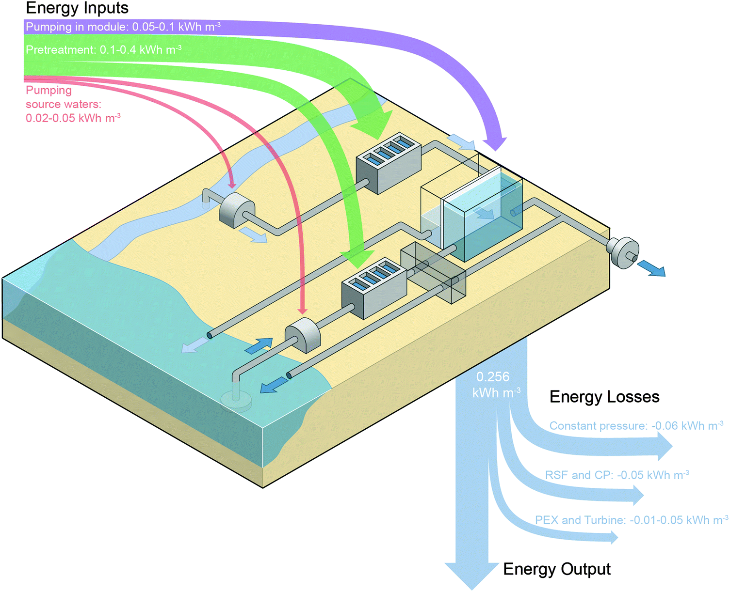 | ||
| Fig. 6 Schematic diagram of PRO system mixing river water and seawater. The feed solution is pumped from the river source, undergoes pretreatment, and then partially permeates across the membrane module. The concentrated stream exiting the feed side of the module is discharged to the ocean. The seawater draw solution is pumped in from the ocean, subjected to pretreatment, and then passes through a pressure exchanger (PEX) before entering the membrane module. The expanded draw volume is either directed through a turbine or routed back through the pressure exchanger for energy recovery before discharge into the ocean. The maximum energy extractable from the system is indicated as 0.256 kW h per cubic meter of total feed and draw solutions—equal to the Gibbs free energy of mixing. Estimates for the dominant energy inputs to the system to pump water in, pretreat the influent water, and pump the solutions through the membrane modules are specified alongside losses from constant-pressure counter-current operation, reverse salt flux (RSF) and concentration polarization (CP), and PEX and turbine inefficiencies. The thickness of each energy input or output arrow denotes the estimated energy. The net extractable energy will be the energy output subtracted by the energy input. | ||
Losses in the membrane module will result in a significant decrease in the energy extractable. As was discussed previously, constant-pressure operation in a counter-current module will reduce the extractable specific energy to 0.192 kW h m−3, a 25% decrease from the Gibbs free energy of mixing.33 Additional losses due to reverse salt flux and concentration polarization in the module will reduce the extractable energy by another 15%, resulting in a specific energy of approximately 0.156 kW h m−3.34
Beyond losses in the membrane module, the energy extractable will also be diminished by inefficiencies in the pressure exchanger and turbine. Turbine losses are straightforward since they will directly affect the power generated, and current turbine efficiencies reach up to 90%.42,45 Pressure exchangers have efficiencies around 95%,42,45,89 but since pressure exchange losses affect all of the incoming draw solution, the actual losses to the system will likely be larger than 5%.
Energetic inputs will surpass the energy that can be produced
The net extractable energy from PRO must account for energy inputs into the system. In the membrane module, pumping energy will be required to push water through the narrow membrane channels and reduce external concentration polarization on either side of the membrane.37,60,86,104 The pressure required for pumping will depend on the crossflow velocity in the membrane module and other hydrodynamic conditions. Experimental measurements have shown the pressure gradient in a spacer filled feed channel to be around 2–5 bar per meter length of module.37,60,86 On the draw side, the pressure drop will be lower, around 0.8 bar m−1.37 Each bar of pumping pressure required translates to 0.03 kW h m−3 of energy consumption.Energy input will also be required to pump source water to the PRO power plant. At locations where rivers run into the sea, the salinity of water does not immediately change from freshwater to salt water compositions.36,105 Instead, large mixing zones exist where the concentration gradually changes, and the size of these zones varies with different tidal and flow conditions. Approximately 30% of worldwide coasts have mixing zones that are spread over such large distances that more energy will be required for pumping source solutions than can be extracted.36 Even with very narrow mixing zones, seawater will likely have to be collected at least 1 km away from the facility, as in desalination plants, to avoid anthropogenic contaminants.106–108 Thus, the energy for pumping raw water from the ocean and rivers will likely range from 0.02–0.05 kW h m−3.93
The largest energy cost in PRO will be for pretreatment of the source solutions before they enter the membrane module. The energetic requirements for pretreatment have not been established entirely. Due to the high fouling propensity of the process, it is likely that the feed stream, which flows into the membrane module during operation, will need extensive pretreatment to remove organic, inorganic, and microbial foulants.38,78,83 The energy for treating the feed stream will likely range between 0.05 and 0.2 kW h m−3 based on energy costs of surface water treatment.91–94 Alternatively, contaminants in the draw stream have been shown to result in minimal membrane fouling, and pretreatment will only be required to remove large particulate matter. This pretreatment energy cost will likely be similar to or lower than that of seawater reverse osmosis pretreatment, which ranges from 0.1 to 0.4 kW h m−3.89,90
Compiling estimates for all the energetic inputs and outputs for a PRO system mixing river water and seawater, it is clear that the expected energetic inputs will surpass the energetic output resulting in a net negative power generation (Fig. 6). The lack of feasibility for the river water and seawater solution pairing is principally due to the low theoretical energy density that can be extracted from these source solutions. Since the energy initially available from the solutions is low, any minor energy inputs will dramatically reduce the amount of power that can be generated. This conclusion has been worked towards in prior studies33–35 and can also help explain the decision of Statkraft, the Norwegian company that pioneered PRO technology, to stop investments in river water and seawater PRO.32
The fact that the energetic requirements of operation are substantially higher than the net output indicates that incremental improvements to the technology, such as more effective membranes, will not enable the feasibility of PRO using river water and seawater. Alternative technologies are also unlikely to improve the prospects of this solution pairing, since all are constrained by the low extractable energy density and require energy for pretreatment and pumping.13,16,18 In fact, PRO has been shown to offer relatively promising efficiencies compared to reverse electrodialysis, another well-developed salinity gradient energy technology.28,29 Other systems have only recently been demonstrated in proof-of-concept studies17,18,109,110 and are unlikely to yield higher efficiencies. Thus, the emergence of a technology that can effectively harvest energy from river water and seawater mixing is far in the future, requiring revolutionary advancements that negate the need for pretreatment and severely reduce inefficiencies.
What other salinity gradient sources is PRO suitable for?
The availability of high salinity brines
Higher concentration gradients with a greater extractable energy density can improve the feasibility of PRO implementation.7,8 For example, when the draw concentration is increased from 0.6 M NaCl (seawater concentration) to 3 M NaCl, the reversible specific energy increases nearly six-fold (Fig. 2). A higher extractable specific energy may allow systems to overcome the previously discussed energetic costs of operation and have a significant net energy output.The success of PRO with increased concentration gradients will only be possible if appropriate, widely available source solutions are identified. Hypersaline lakes are suitable candidates for the process, since they exist in many locations across the globe. The Dead Sea, bordered by Israel, Jordan, and Palestine, has been considered for PRO.52,111 The sea has a 34% salinity,112 making the reversible energy of mixing when combined with freshwater around 2.52 kW h m−3 (eqn (4))—about an order of magnitude higher than that available from the river water and seawater system. There is also a relatively sizable amount of inflow entering the Dead Sea, approximately 100 million cubic meters (MCM) per year from the Jordan River113 and another 200 MCM per year will be sourced from the Rea Sea.114 In total, the amount of energy that will be released from inflow into the Dead Sea is around 1.6 TW h per year, equal to 180 MW of continuous power (assuming infinite dilution of inflow waters). Additionally, the Dead Sea is only hospitable to bacteria, so there is a relatively low risk of damaging the environment by installing a potential plant.
The Great Salt Lake in Utah is another widely considered hypersaline lake.8 The salinity of the Great Salt Lake is lower than the Dead Sea, around 27%,8 which results in an extractable specific energy of approximately 2.26 kW h m−3 when mixing with fresh water. The amount of inflow into the Great Salt Lake from its three river tributaries is much greater than the Dead Sea, around 3700 MCM per year,115 and the total energy released from these inflows is approximately 22.7 TW h per year (2600 MW).
Highly saline resources other than hypersaline lakes may also be suitable for PRO. For example, produced water from hydraulic fracturing in the Marcellus shale has an average total dissolved solids content of approximately 190000 mg L−1.116 At times, treated produced water, which is still extremely high in salinity, is mixed directly with wastewater, allowing an opportunity for energy extraction.117 Salt domes are also sizable potential sources of highly saline waters that can be mixed with brackish water or seawater.118 However, salt domes and produced water are relatively unexplored in literature; further studies are needed to determine the practicality of these unconventional sources.
High concentration differences require advances in PRO technology
In order to efficiently extract energy from higher concentration solution pairings, membrane modules will need to be tailored for these systems. One established requirement for PRO with increased concentration gradients is a higher operating pressure in the system.87 Both the power density and specific energy of a membrane module are found to reach their maximum when the system is operated with a hydraulic pressure equal to approximately half the osmotic pressure difference between the feed and draw solutions.33–35 Meeting this condition with extremely saline solutions, such as water from the Dead Sea with an osmotic pressure around 507 bar, will be nearly impossible. However, any gain in the operating pressure achievable will improve the efficiency of energy extraction.Fabricating membranes that can reach high operating pressures while maintaining suitably low support layer structural parameters has proven experimentally difficult.59,64,119–121Fig. 7 shows the maximum operating pressure of the most robust membranes in literature and their calculated structural parameters.22,24,59,60,87 It is evident that, to achieve operation at higher pressures, a thicker support with a higher structural parameter is needed. The highest operating pressure of a membrane suitable for PRO in the literature is approximately 55 bar, far lower than the ideal pressure for highly saline solutions, with a structural parameter of around 700 μm.60,87 More studies will be needed to identify the structural characteristics of membranes that can operate at higher pressures and translate bench-scale experimental results to large membrane modules.
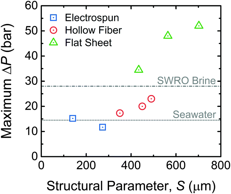 | ||
| Fig. 7 Maximum operating pressure of a given membrane as a function of the support layer structural parameter. Data from select flat sheet membranes with electrospun support layers,22,59 hollow fiber membranes with support layers formed by phase inversion,24 and commercial flat sheet membranes with phase inversion support layers are shown.60,87 All membranes were thin-film composites with a polyamide active layer. Also indicated are the optimal operating pressures for seawater and seawater reverse osmosis (SWRO) brine draw solutions calculated as half of the osmotic pressure of the respective solution. | ||
Besides a higher pumping pressure, there will be additional challenges to the implementation of PRO with hypersaline sources. The selectivity of polyamide membranes has been shown to decrease with higher concentration draw solutions, and performance losses due to exacerbated reverse salt flux may be very detrimental to the overall efficiency.60,122 Additionally, if higher salinity feeds are used, concentration polarization inside the support layer may cause scaling within the membrane.123 Further experimental studies will be needed to identify and overcome challenges associated with high salinity solution pairings.
Will PRO reduce the energy of seawater desalination?
Impaired water can be used to decrease the energy of desalination in hybrid RO–PRO systems
As worldwide fresh water resources are increasingly depleted, the use of seawater desalination is growing rapidly to augment existing supplies beyond what is obtainable from the natural hydrologic cycle.98,124 While reverse osmosis (RO), the fastest growing desalination technology, has seen tremendous improvements in efficiency, one of the major drawbacks of seawater desalination of any kind is the relatively high energy input required compared to conventional fresh water treatment.89,125,126 In state-of-the-art RO systems, which approach the practical limit of achievable efficiency, the energy requirement is still greater than 2 kW h per cubic meter of desalinated water.98Hybrid RO–PRO systems have been proposed to reduce the energy needed for desalination.50,127–131 In these systems, shown schematically in Fig. 8, low-salinity impaired water sources, such as wastewater effluent, will undergo controlled mixing in PRO with the concentrated brine stream from RO desalination, which is normally wasted through discharge back into the environment.104,131 PRO therefore functions as a technology that simultaneously recovers the energy available from the RO brine stream and also brings additional power into the system using the available impaired water sources. In theory, hybrid RO–PRO systems are also advantageous because the RO brine is diluted by wastewater effluent before discharge into the ocean, minimizing the environment impact.31
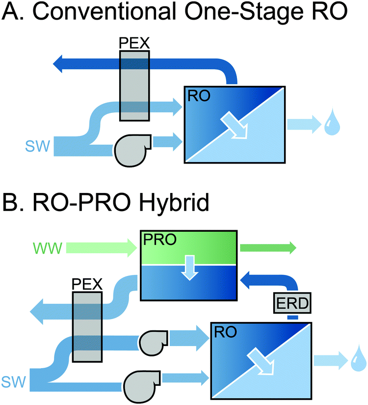 | ||
| Fig. 8 (A) Schematic diagram of a one-stage reverse osmosis (RO) system with energy recovery through a pressure exchanger (PEX) for seawater (SW) desalination. (B) Hybrid pressure-retarded osmosis (PRO) and RO system mixing wastewater effluent (WW) or impaired water with the concentrated RO brine stream after it passes through an energy recovery device (ERD) that decreases the hydraulic pressure. Darker colors correspond to more concentrated solutions and the thickness of each arrow denotes the approximate flow rate. | ||
The potential for reducing the energy of seawater desalination in the RO–PRO hybrid system can be quantified by determining the minimum specific energy of desalination, SED, which is defined as the lowest amount of energy required to generate a unit volume of permeate water in an idealized system. This metric has been used to identify the practical minimum energy needed for desalination with different schemes and assumes ideal system components, perfectly selective membranes, ideal solutions, and no mass transfer limitations.132 With these simplifying assumptions, analytical equations can be derived that describe the energy consumption with few assumed parameters. The derivation and details of the equations used are described in the Appendix.
Fig. 9 shows the minimum specific energy of desalination as a function of the water recovery (i.e., the flow rate of permeate water divided by the flow rate of influent seawater). The energy consumption for the conventional one-stage RO system (solid black line) is plotted alongside curves for the RO–PRO system with three different impaired water to seawater flow rate ratios, QWW/QSW. For all configurations, the specific energy consumption increases at higher recoveries, since the final brine osmotic pressure is higher, and thus more pumping energy is required in the RO module. As would be expected in these idealized scenarios, the RO–PRO system always demonstrates improved performance as compared to the one-stage RO system due to the use of impaired water, and the system can even use less energy than the reversible thermodynamic minimum energy of separation for seawater alone. Increasing the amount of impaired water available improves the effectiveness of the RO–PRO system. The typical recovery range for an RO desalination system is from 0.4–0.6.89 At a recovery of 0.5, the RO–PRO system can reduce energy consumption as compared to a one-stage RO system by 28%, 49%, and 65% for QWW/QSW of 0.2, 0.5, and 1.0, respectively. At very low recoveries, the RO–PRO system will theoretically generate power, as indicated by a negative specific energy of desalination. This impractical power generation scenario occurs because most of the seawater will be transferred directly to the PRO system, which would behave similar to a river water and seawater mixing system. At high recoveries, the advantage of the RO–PRO system diminishes since a smaller brine flow rate is transferred from the RO module to the PRO system.
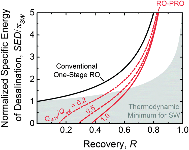 | ||
| Fig. 9 Normalized specific energy consumption of seawater desalination, SED, as a function of water recovery, R, for a one-stage reverse osmosis (RO) system (black line) and a hybrid RO and pressure-retarded osmosis (PRO) system (red lines). The ratio of wastewater effluent to seawater flow rates, QWW/QSW, used in the RO–PRO system is set to 0.2 (short dashed line), 0.5 (long dashed line), and 1.0 (solid line). The normalized specific energy is the amount of energy required to generate a given permeate volume, SED, divided by the osmotic pressure of the feed seawater solution, πSW. For a typical seawater concentration of 0.6 M NaCl, one unit of SED/πSW is equal to 0.83 kW h m−3. The minimum energy of desalination for an ideal reversible thermodynamic process without the use of impaired water is also shown (top of gray shaded region). The modeling of the one-stage RO and RO–PRO system assumes ideal solutions, perfectly selective membranes, no mass transfer limitations, and ideal system components. All data assumed a 60:1 seawater to wastewater salinity ratio corresponding to a 0.6 M NaCl seawater solution and a 10 mM NaCl wastewater effluent source. | ||
Theoretically, the RO–PRO system can be more advantageous than alternative methods to improve the conventional one-stage RO system. For example, the addition of multiple stages of reverse osmosis operating at distinct applied hydraulic pressures has been discussed as a method to reduce the energy of desalination.98,132 As more stages are added to the system, the specific energy of consumption will approach the thermodynamic minimum for seawater shown in Fig. 9 (top of grey shaded region). While multiple-stage systems allow for a more homogenous distribution of the driving force for RO and hence are favorable at high recoveries, the RO–PRO system shows improved performance in the reasonable recovery range around 0.5 if sufficient impaired water is available (QWW/QSW is at least 0.25). The RO–PRO system is also more effective than directly diluting the feed seawater with impaired water. For example, if the seawater were premixed with impaired water at a QWW/QSW of 0.2, the feed would be diluted to 83% of the seawater concentration and thus the energy of desalination would be reduced by 17% instead of 28% with the RO–PRO system.
From the idealized energetic analysis, we can conclude the hybrid RO–PRO system is theoretically favorable if (1) impaired water sources are available in large quantities and (2) medium to low water recoveries are needed. In a system where one-third of the total source water is obtained from wastewater effluent (i.e., QWW/QSW = 0.5), the RO–PRO system will theoretically be able to reduce the specific energy consumption of desalination by one half.
Practical considerations will hinder the implementation of RO–PRO
The idealized modeling discussed in the previous subsection identified that, if a suitable amount of impaired water is available, the hybrid RO–PRO system has a favorable theoretical potential. However, realistic losses, such as imperfect efficiency in the pressure exchanger and pumps of the system, will reduce to the power savings achievable in the process. As with the river water and seawater PRO system, these losses may threaten the theoretical energetic gains that come from the addition of a PRO stage. If energy consumption can be reduced using the RO–PRO hybrid system, the cost of energy saved will have to sufficiently offset the additional cost of membranes and other system components.Fouling will likely be the biggest technical challenge for the combined RO–PRO system since any low-value impaired water source will be heavily loaded with foulants.133 As was discussed previously, the membrane orientation in PRO renders it uniquely vulnerable to fouling from the feed solution. For example, lab-scale experiments with model wastewater effluent have observed dramatic flux decline (50%) due to severe biofouling.78 This wastewater effluent fouling is highly irreversible, as even extensive cleaning methods such as osmotic backwashing have only been shown to recover 14% of the flux.78
An additional consideration is the practicality of using impaired water sources to supplement seawater desalination, rather than utilizing these sources directly through wastewater reclamation. Studies have shown that for regions where water demand exceeds what is available from the natural hydrogeological cycle, wastewater reclamation for non-potable reuse can offer energy savings as compared to seawater desalination.134,135 There are also environmental benefits to utilizing wastewater reclamation, such as a reduction in greenhouse gas emissions compared to seawater desalination.134 Given the substantial pretreatment of impaired water that may be required to prevent immediate clogging of the PRO system, it is likely more worthwhile to use the low-salinity waters directly. Thus, even though the RO–PRO process is theoretically promising in a highly simplified analysis, practical limitations will likely threaten the output of the process. Future studies modeling the energy savings of the RO–PRO system will need to identify whether, when inefficiencies and fouling are accounted for, the use of impaired water at a desalination facilities outweighs the benefit of directly reclaiming wastewater.
Outlook
The considerable potential of salinity gradient energy extraction using pressure-retarded osmosis has been discussed in the literature for decades. In this critical review, we have summarized simple energetic analyses and arguments that clearly illustrate the challenges in obtaining a net positive extractable energy. These difficulties arise from a few key factors. First, the volumetric energy density of salinity gradient mixing, which represents the thermodynamic maximum energy extractable, is relatively low, ranging from 0.26 kW h m−3 for seawater and river water to around 2.52 kW h m−3 for hypersaline solutions. Second, significant energetic losses occur during PRO energy conversion due to practical constraints necessary for operation, such the need for continuous constant-pressure operation, that reduce the efficiency of energy extraction by at least 30%. Last, energetic inputs are required for pretreatment, which is necessary to mitigate severe and irreversible fouling that occurs in PRO, and pumping to circulate water in the membrane modules and create hydrodynamic conditions that reduce concentration polarization; these energetic inputs will likely amount to more than 0.1 kW h m−3.The river water and seawater solution pairing, despite the remarkably high global theoretical potential, will not produce net energy in the currently envisioned process because the specific energy extractable will be less than the energetic inputs of the process after inefficiencies are accounted for. Alternative salinity gradient energy technologies will not improve the outlook of the river water and seawater solution pairing, since all systems are constrained by the thermodynamic limit of extractable energy and any envisioned process will require some extent of pretreatment and pumping energy.
Hybrid systems that use PRO to reduce the energy of RO desalination by mixing the concentrated seawater brine with low-salinity impaired water sources may also be unfeasible. While the theoretical energy that can be recovered with hybrid RO–PRO system is substantial if enough wastewater is available, arid regions that require desalination will find it more efficient and beneficial to use impaired water sources directly through wastewater reclamation. Additionally, fouling of membranes from the impaired water streams will result in severe performance losses.
Solution pairings with higher concentration differences and, thus, theoretical energy densities up to an order of magnitude higher than that of the river water and seawater system can be potentially viable in the near future. While hypersaline lakes and saline wastewaters from the oil and gas industry may be potential sources, further possible solution pairings must be identified. Additionally, membrane modules that can withstand high operating pressures are needed to efficiently extract energy from hypersaline sources.
Recent literature on PRO has been dominated by laboratory studies aiming to improve coupon-scale power densities, which are not relevant to full-scale system performance. Instead, further research is critically needed to improve the energetic efficiency of the process by creating membranes that negate the need for pretreatment or demonstrate fundamentally improved selectivity. Alongside radical membrane improvements, advancements are needed to push forward relatively unexplored alternative solution pairings with higher concentration gradients than the conventional river water and seawater system. Other emerging technologies should be investigated alongside PRO, but these must be evaluated based on their net energetic efficiency rather than small-scale power densities. Only through revolutionary improvements to the technology and by selecting feasible configurations will the decades-long vision of sustainable osmotic power be realized.
Appendix: energy of desalination in the RO–PRO hybrid system
At the theoretical limit of constant-pressure operation, the one-stage reverse osmosis (RO) system (Fig. 8A) will operate with an applied hydraulic pressure that is equal to the final osmotic pressure of the brine exiting the RO module. Thus, the minimum specific energy of desalination for the one-stage RO process, SED1, is equal to the final brine osmotic pressure:98,132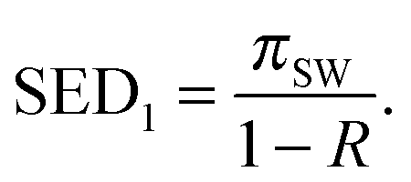 | (A.1) |
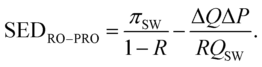
The RO and pressure-retarded osmosis (PRO) hybrid system (Fig. 8B) uses a PRO module to recover a portion of the mixing power available when the high-salinity RO brine stream is contacted with a low-salinity wastewater effluent (WW) or impaired water stream. The energy saved by the PRO module is equal to the permeation flow rate across the PRO module, ΔQ, multiplied by the hydraulic pressure difference across the PRO module, ΔP.33,34 The specific energy of desalination in the RO–PRO hybrid, SEDRO–PRO, can be determined by simply subtracting the energy gained in the PRO stage from the energy consumption of a one-stage RO module:
 | (A.2) |
The power recovered in PRO is maximized when the driving force at both ends of the module approaches zero (i.e., the osmotic pressure difference is equal to the hydraulic pressure difference).33 In a counter-current system meeting this requirement, the draw stream exits the module at an osmotic pressure equal to the sum of the osmotic pressure of the wastewater effluent, πWW, and the applied hydraulic pressure. The inlet flow rate of the draw stream is (1 − R)QSW, and equilibrium at the feed inlet can be described:33
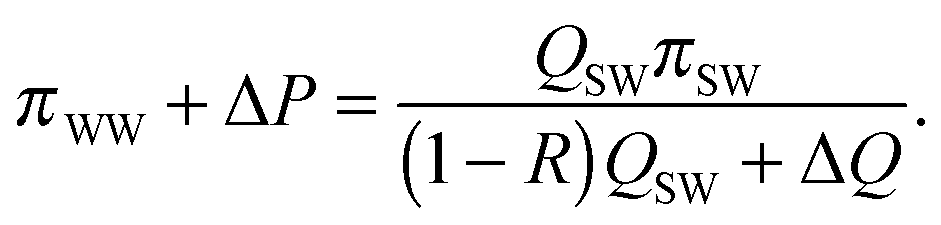 | (A.3) |
Similarly, the feed solution exits the module at an osmotic pressure equal to the osmotic pressure of the RO brine, πSW/(1 − R), subtracted by the applied hydraulic pressure. The equilibrium condition at the draw inlet side of the PRO module can also be expressed:33
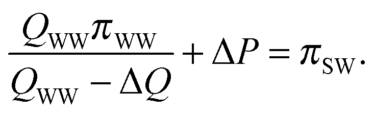 | (A.4) |
To determine SEDRO–PRO at the optimum applied hydraulic pressure in the PRO module, eqn (A.3) and (A.4) are solved simultaneously to find ΔQ and ΔP. Eqn (A.2) is then used to calculate the overall specific energy of desalination in the RO–PRO hybrid, which is dependent on R, the wastewater effluent to seawater flow rate ratio (QWW/QSW), and the wastewater effluent to seawater osmotic pressure ratio (πWW/πSW).
Acknowledgements
We acknowledge the National Science Foundation Graduate Research Fellowship DGE-1122492 awarded to A. P. S. and the support received from the National Science Foundation under Award Number CBET 1232619.Notes and references
- M. I. Hoffert, K. Caldeira, G. Benford, D. R. Criswell, C. Green, H. Herzog, A. K. Jain, H. S. Kheshgi, K. S. Lackner, J. S. Lewis, H. D. Lightfoot, W. Manheimer, J. C. Mankins, M. E. Mauel, L. J. Perkins, M. E. Schlesinger, T. Volk and T. M. L. Wigley, Science, 2002, 298, 981–987 CrossRef CAS PubMed.
- B. E. Logan and M. Elimelech, Nature, 2012, 488, 313–319 CrossRef CAS PubMed.
- R. E. Pattle, Nature, 1954, 174, 660 CrossRef CAS.
- R. S. Norman, Science, 1974, 186, 350–352 CAS.
- A. Dai and K. Trenberth, J. Hydrometeorol., 2002, 3, 660–687 CrossRef.
- F. La Mantia, M. Pasta and H. Deshazer, Nano Lett., 2011, 11, 1810–1813 CrossRef CAS PubMed.
- S. Loeb, Desalination, 1998, 120, 247–262 CrossRef CAS.
- S. Loeb, Desalination, 2001, 141, 85–91 CrossRef CAS.
- T. Thorsen and T. Holt, J. Membr. Sci., 2009, 335, 103–110 CrossRef CAS.
- S. Loeb, Science, 1975, 189, 654–655 CAS.
- A. Achilli and A. E. Childress, Desalination, 2010, 261, 205–211 CrossRef CAS.
- C. Klaysom, T. Y. Cath, T. Depuydt and I. F. J. Vankelecom, Chem. Soc. Rev., 2013, 42, 6959–6989 RSC.
- N. Y. Yip, D. A. Vermaas, K. Nijmeijer and M. Elimelech, Environ. Sci. Technol., 2014, 48, 4925–4936 CrossRef CAS PubMed.
- A. Daniilidis, D. A. Vermaas, R. Herber and K. Nijmeijer, Renewable Energy, 2014, 64, 123–131 CrossRef CAS.
- D. Vermaas, J. Veerman, N. Y. Yip, M. Elimelech, M. Saakes and K. Nijmeijer, ACS Sustainable Chem. Eng., 2013, 1, 1295–1302 CrossRef CAS.
- M. C. Hatzell, R. D. Cusick and B. E. Logan, Energy Environ. Sci., 2014, 7, 1159–1165 CAS.
- R. Rica, R. Ziano, D. Salerno, F. Mantegazza, R. van Roij and D. Brogioli, Entropy, 2013, 15, 1388–1407 CrossRef.
- X. Zhu, W. Yang, M. C. Hatzell and B. E. Logan, Environ. Sci. Technol., 2014, 48, 7157–7163 CrossRef CAS PubMed.
- F. Helfer, C. Lemckert and Y. G. Anissimov, J. Membr. Sci., 2014, 453, 337–358 CrossRef CAS.
- N. Y. Yip, A. Tiraferri, W. A. Phillip, J. D. Shiffman and M. Elimelech, Environ. Sci. Technol., 2010, 44, 3812–3818 CrossRef CAS PubMed.
- N. Y. Yip, A. Tiraferri, W. A. Phillip, J. D. Schiffman, L. A. Hoover, Y. C. Kim and M. Elimelech, Environ. Sci. Technol., 2011, 45, 4360–4369 CrossRef CAS PubMed.
- X. Song, Z. Liu and D. D. Sun, Energy Environ. Sci., 2013, 6, 1199–1210 CAS.
- S. Chou, R. Wang, L. Shi, Q. She, C. Tang and A. G. Fane, J. Membr. Sci., 2012, 389, 25–33 CrossRef CAS.
- S. Zhang and T. S. Chung, Environ. Sci. Technol., 2013, 47, 10085–10092 CrossRef CAS PubMed.
- E. Sivertsen, T. Holt, W. Thelin and G. Brekke, J. Membr. Sci., 2012, 417–418, 69–79 CrossRef CAS.
- A. Achilli, T. Y. Cath and A. E. Childress, J. Membr. Sci., 2009, 343, 42–52 CrossRef CAS.
- E. Nagy, J. Membr. Sci., 2014, 460, 71–81 CrossRef CAS.
- N. Y. Yip and M. Elimelech, Environ. Sci. Technol., 2014, 48, 11002–11012 CrossRef CAS PubMed.
- G. Z. Ramon, B. J. Feinberg and E. M. V. Hoek, Energy Environ. Sci., 2011, 4, 4423–4434 CAS.
- Statkraft, Crown Princess to open world's first osmotic power plant, Press Release, Oslo, Norway, 2009.
- M. Kurihara and M. Hanakawa, Desalination, 2013, 308, 131–137 CrossRef CAS.
- Statkraft, Statkraft halts osmotic power investments, Press Release, Oslo, Norway, 2013.
- S. Lin, A. P. Straub and M. Elimelech, Energy Environ. Sci., 2014, 7, 2706–2714 CAS.
- A. P. Straub, S. Lin and M. Elimelech, Environ. Sci. Technol., 2014, 48, 12435–12444 CrossRef CAS PubMed.
- K. K. Reimund, J. R. Mccutcheon and A. D. Wilson, J. Membr. Sci., 2015, 487, 240–248 CrossRef CAS.
- O. Alvarez-Silva, C. Winter and A. Osorio, Environ. Sci. Technol. Lett., 2014, 1, 410–415 CrossRef CAS.
- Y. C. Kim, Y. Kim, D. Oh and K. H. Lee, Environ. Sci. Technol., 2013, 47, 2966–2973 CrossRef CAS PubMed.
- N. Y. Yip and M. Elimelech, Environ. Sci. Technol., 2013, 47, 12607–12616 CrossRef CAS PubMed.
- S. C. Chen, C. F. Wan and T.-S. Chung, J. Membr. Sci., 2015, 479, 190–203 CrossRef CAS.
- G. Han, S. Zhang, X. Li and T. S. Chung, J. Membr. Sci., 2013, 440, 108–121 CrossRef CAS.
- S. E. Skilhagen, Desalin. Water Treat., 2010, 15, 271–278 CrossRef.
- S. Loeb, Desalination, 2002, 143, 115–122 CrossRef CAS.
- G. Han, S. Zhang, X. Li and T.-S. Chung, Prog. Polym. Sci., 2015, 51, 1–27 CrossRef.
- K. Lee, R. Baker and H. Lonsdale, J. Membr. Sci., 1981, 8, 141–171 CrossRef CAS.
- B. J. Feinberg, G. Z. Ramon and E. M. V Hoek, J. Membr. Sci., 2015, 476, 311–320 CrossRef CAS.
- N. Y. Yip and M. Elimelech, Environ. Sci. Technol., 2012, 46, 5230–5239 CrossRef CAS PubMed.
- L. D. Banchik, M. H. Sharqawy and J. H. Lienhard, J. Membr. Sci., 2014, 468, 81–89 CrossRef CAS.
- S. Loeb, J. Membr. Sci., 1990, 51, 323–335 CrossRef CAS.
- A. Seppälä and M. J. Lampinen, J. Membr. Sci., 1999, 161, 115–138 CrossRef.
- M. H. Sharqawy, S. M. Zubair and J. H. Lienhard, Energy, 2011, 36, 6617–6626 CrossRef CAS.
- N. M. Bazhin, Desalination, 2015, 375, 21–23 CrossRef CAS.
- S. Loeb, J. Membr. Sci., 1976, 1, 49–63 CrossRef.
- J. W. Post, H. V. M. Hamelers and C. J. N. Buisman, Environ. Sci. Technol., 2008, 42, 5785–5790 CrossRef CAS PubMed.
- R. W. Baker, Membrane Technology and Applications, J. Wiley, New York, 2nd edn, 2004 Search PubMed.
- W. A. Phillip, J. S. Yong and M. Elimelech, Environ. Sci. Technol., 2010, 44, 5170–5176 CrossRef CAS PubMed.
- J. R. McCutcheon and M. Elimelech, J. Membr. Sci., 2006, 284, 237–247 CrossRef CAS.
- G. T. Gray, J. R. McCutcheon and M. Elimelech, Desalination, 2006, 197, 1–8 CrossRef CAS.
- G. D. Mehta and S. Loeb, J. Membr. Sci., 1978, 4, 261–265 CrossRef CAS.
- N. Bui and J. McCutcheon, Environ. Sci. Technol., 2014, 48, 4129–4136 CrossRef CAS PubMed.
- A. P. Straub, C. O. Osuji, T. Y. Cath and M. Elimelech, Environ. Sci. Technol., 2015, 49, 12551–12559 CrossRef CAS PubMed.
- N. Y. Yip and M. Elimelech, Environ. Sci. Technol., 2011, 45, 10273–10282 CrossRef CAS PubMed.
- S. Chou, R. Wang and A. G. Fane, J. Membr. Sci., 2013, 448, 44–54 CrossRef CAS.
- N. Bui and J. R. McCutcheon, Environ. Sci. Technol., 2013, 47, 1761–1769 CAS.
- G. Han, P. Wang and T. S. Chung, Environ. Sci. Technol., 2013, 47, 8070–8077 CrossRef CAS PubMed.
- N. Bui, J. T. Arena and J. R. McCutcheon, J. Membr. Sci., 2015, 492, 289–302 CrossRef CAS.
- E. Sivertsen, T. Holt, W. R. Thelin and G. Brekke, J. Membr. Sci., 2015, 489, 299–307 CrossRef CAS.
- Q. She, X. Jin and C. Y. Tang, J. Membr. Sci., 2012, 401, 262–273 CrossRef.
- J. E. Cadotte, R. J. Petersen, R. E. Larson and E. E. Erickson, Desalination, 1980, 32, 25–31 CrossRef.
- M. Kumar, M. Grzelakowski, J. Zilles, M. Clark and W. Meier, Proc. Natl. Acad. Sci. U. S. A., 2007, 104, 20719–20724 Search PubMed.
- B. Corry, J. Phys. Chem. B, 2008, 112, 1427–1434 CrossRef CAS PubMed.
- R. E. Larson, J. E. Cadotte and R. J. Petersen, Desalination, 1981, 38, 473–483 CrossRef CAS.
- A. F. Ismail, M. Padaki, N. Hilal, T. Matsuura and W. J. Lau, Desalination, 2015, 356, 140–148 CrossRef CAS.
- G. M. Geise, H. B. Park, A. C. Sagle, B. D. Freeman and J. E. McGrath, J. Membr. Sci., 2011, 369, 130–138 CrossRef CAS.
- G. M. Geise, D. R. Paul and B. D. Freeman, Prog. Polym. Sci., 2014, 39, 1–42 Search PubMed.
- J. Maisonneuve, P. Pillay and C. B. Laflamme, Renewable Energy, 2015, 75, 416–424 CrossRef.
- Y. C. Kim and M. Elimelech, Environ. Sci. Technol., 2012, 46, 4673–4681 CrossRef CAS PubMed.
- A. Tiraferri, N. Y. Yip, A. P. Straub, S. Romero-Vargas Castrillón and M. Elimelech, J. Membr. Sci., 2013, 444, 523–538 CrossRef CAS.
- E. Bar-zeev, F. Perreault, A. P. Straub and M. Elimelech, Environ. Sci. Technol., 2015, 49, 13050–13058 CrossRef CAS PubMed.
- Q. She, Y. K. W. Wong, S. Zhao and C. Y. Tang, J. Membr. Sci., 2013, 428, 181–189 CrossRef CAS.
- J. W. Sim, S. H. Nam, J. W. Koo, Y. J. Choi and T. M. Hwang, Desalin. Water Treat., 2015 DOI:10.1080/19443994.2015.1040269.
- B. Mi and M. Elimelech, J. Membr. Sci., 2008, 320, 292–302 CrossRef CAS.
- C. Kim, S. Lee and S. Hong, Desalin. Water Treat., 2012, 43, 314–322 CrossRef CAS.
- D. I. Kim, J. Kim, H. K. Shon and S. Hong, J. Membr. Sci., 2015, 483, 34–41 CrossRef CAS.
- D. L. Shaffer, J. R. Werber, H. Jaramillo, S. Lin and M. Elimelech, Desalination, 2014, 356, 271–284 CrossRef.
- Y. Kim, M. Elimelech, H. K. Shon and S. Hong, J. Membr. Sci., 2014, 460, 206–212 CrossRef CAS.
- Q. She, D. Hou, J. Liu, K. H. Tan and C. Y. Tang, J. Membr. Sci., 2013, 445, 170–182 CrossRef CAS.
- A. Straub, N. Yip and M. Elimelech, Environ. Sci. Technol. Lett., 2014, 1, 55–59 CrossRef CAS.
- W. R. Thelin, E. Sivertsen, T. Holt and G. Brekke, J. Membr. Sci., 2013, 438, 46–56 CrossRef CAS.
- C. Fritzmann, J. Löwenberg, T. Wintgens and T. Melin, Desalination, 2007, 216, 1–76 CrossRef CAS.
- WateReuse Association, Seawater Desalination Power Consumption, White Paper, Arlington, Virginia, 2011.
- G. Klein, M. Krebs, V. Hall, T. O'Brien and B. B. Blevins, California's Water-Energy Relationship, Calif. Energy Comm., Sacramento, California, 2005 Search PubMed.
- M. Tripathi, Life-Cycle Energy and Emissions for Municipal Water and Wastewater Services, Univ. Michigan Cent. Sustain. Syst., Ann Arbor, Michigan, 2007.
- A. K. Plappally and J. H. Lienhard V, Renewable Sustainable Energy Rev., 2012, 16, 4818–4848 CrossRef.
- G. Crozes, D. Hugaboom and S. Grooters, Demonstration of Low-Pressure Membrane Technologies on Lake Michigan Water, Energy Cent. Wisconsin Rep., Luxemburg, Wisconsin, 2003 Search PubMed.
- E. Ostuni, R. G. Chapman, R. E. Holmlin, S. Takayama and G. M. Whitesides, Langmuir, 2001, 17, 5605–5620 CrossRef CAS.
- M. Elimelech, X. Zhu, A. E. Childress and S. Hong, J. Membr. Sci., 1997, 127, 101–109 CrossRef CAS.
- D. Rana and T. Matsuura, Chem. Rev., 2010, 110, 2448–2471 CrossRef CAS PubMed.
- M. Elimelech and W. A. Phillip, Science, 2011, 333, 712–717 CrossRef CAS PubMed.
- D. L. Shaffer, H. Jaramillo, S. Romero-Vargas Castrillón, X. Lu and M. Elimelech, J. Membr. Sci., 2015, 490, 209–219 CrossRef CAS.
- X. Li, T. Cai and T.-S. Chung, Environ. Sci. Technol., 2014, 48, 9898–9907 CrossRef CAS PubMed.
- J. Maisonneuve, P. Pillay and C. B. La, Renewable Energy, 2015, 81, 62–70 CrossRef.
- Int. Energy Agency Key World Energy Stat., 2014.
- M. A. Hiltzik, New York Free Press, 2010 Search PubMed.
- A. Achilli, J. L. Prante, N. T. Hancock, E. B. Maxwell and A. E. Childress, Environ. Sci. Technol., 2014, 48, 6437–6443 CrossRef CAS PubMed.
- O. Alvarez-Silva and A. F. Osorio, Renewable Energy, 2015, 74, 737–748 CrossRef CAS.
- Y. Dreizin, A. Tenne and D. Hoffman, Desalination, 2008, 220, 132–149 CrossRef CAS.
- B. Sauvet-Goichon, Desalination, 2007, 203, 75–81 CrossRef CAS.
- D. Gille, Desalination, 2003, 156, 249–256 CrossRef CAS.
- A. Siria, P. Poncharal, A.-L. Biance, R. Fulcrand, X. Blase, S. T. Purcell and L. Bocquet, Nature, 2013, 494, 455–458 CrossRef CAS PubMed.
- W. Guo, L. Cao, J. Xia, F.-Q. Nie, W. Ma, J. Xue, Y. Song, D. Zhu, Y. Wang and L. Jiang, Adv. Funct. Mater., 2010, 20, 1339–1344 CrossRef CAS.
- S. Loeb, F. V. A. N. Hessen and D. Shahaf, J. Membr. Sci., 1976, 1, 249–269 CrossRef CAS.
- A. M. Salhotra, E. E. Adams and D. R. F. Harleman, Water Resour. Res., 1985, 21, 1336–1344 CrossRef CAS.
- E. Farber, A. Vengosh, I. Gavrieli, A. Marie, T. D. Bullen, B. Mayer, R. Holtzman, M. Segal and U. Shavit, Geochim. Cosmochim. Acta, 2004, 68, 1989–2006 CrossRef CAS.
- World Bank, Red Sea-Dead Sea Water Conveyance Study Program, 2011.
- R. L. Baskin, K. M. Waddell, S. A. Thiros, E. M. Giddings, H. K. Hadley, D. W. Stephens and S. J. Gerner, U.S. Geol. Surv., 2002.
- D. L. Shaffer, L. H. Arias Chavez, M. Ben-Sasson, S. Romero-Vargas Castrillón, N. Y. Yip and M. Elimelech, Environ. Sci. Technol., 2013, 47, 9569–9583 CrossRef CAS PubMed.
- N. R. Warner, C. A. Christie, R. B. Jackson and A. Vengosh, Environ. Sci. Technol., 2013, 47, 11849–11857 CrossRef CAS PubMed.
- G. Wick and J. Isaacs, Science, 1978, 199, 1436–1437 CAS.
- Y. Li, R. Wang, S. Qi and C. Tang, J. Membr. Sci., 2015, 488, 143–153 CrossRef CAS.
- X. Li, S. Zhang, F. Fu and T.-S. Chung, J. Membr. Sci., 2013, 434, 204–217 CrossRef CAS.
- S. Zhang, F. Fu and T.-S. Chung, Chem. Eng. Sci., 2013, 87, 40–50 CrossRef CAS.
- S. Bason, Y. Oren and V. Freger, J. Membr. Sci., 2011, 367, 119–126 CrossRef CAS.
- M. Zhang, D. Hou, Q. She and C. Y. Tang, Water Res., 2014, 48, 387–395 CrossRef CAS PubMed.
- R. L. McGinnis and M. Elimelech, Environ. Sci. Technol., 2008, 42, 8625–8629 CrossRef CAS PubMed.
- L. F. Greenlee, D. F. Lawler, B. D. Freeman, B. Marrot and P. Moulin, Water Res., 2009, 43, 2317–2348 CrossRef CAS PubMed.
- R. Semiat, Environ. Sci. Technol., 2008, 42, 8193–8201 CrossRef CAS PubMed.
- A. Altaee, G. Zaragoza and A. Sharif, Desalination, 2014, 344, 108–115 CrossRef CAS.
- B. J. Feinberg, G. Z. Ramon and E. M. V Hoek, Environ. Sci. Technol., 2013, 47, 2982–2989 CrossRef CAS PubMed.
- W. He, Y. Wang, A. Sharif and M. H. Shaheed, Desalination, 2014, 352, 27–37 CrossRef CAS.
- J. Kim, M. Park, S. A. Snyder and J. H. Kim, Desalination, 2013, 322, 121–130 CrossRef CAS.
- J. L. Prante, J. A. Ruskowitz, A. E. Childress and A. Achilli, Appl. Energy, 2014, 120, 104–114 CrossRef CAS.
- S. Lin and M. Elimelech, Desalination, 2015, 366, 9–14 CrossRef CAS.
- K. Saito, M. Irie, S. Zaitsu, H. Sakai, H. Hayashi and A. Tanioka, Desalin. Water Treat., 2012, 41, 114–121 CrossRef CAS.
- W. Mo, R. Wang and J. B. Zimmerman, Environ. Sci. Technol., 2014, 48, 5883–5891 CrossRef CAS PubMed.
- I. Muñoz, L. Milà-I-Canals and A. R. Fernández-Alba, J. Ind. Ecol., 2010, 14, 902–918 CrossRef.
| This journal is © The Royal Society of Chemistry 2016 |