
 Open Access Article
 This Open Access Article is licensed under a Creative Commons Attribution-Non Commercial 3.0 Unported Licence
Investigation of helium at a Y2Ti2O7 nanocluster embedded in a BCC Fe matrix
Thomas
Danielson
*a,
Eric
Tea
 b and
Celine
Hin
ab
b and
Celine
Hin
ab
aDepartment of Materials Science and Engineering, Virginia Polytechnic Institute and State University, 635 Prices Fork Road, Blacksburg, VA 24060, USA. E-mail: thomasd1@vt.edu; Tel: +1-(309)-368-9174
bDepartment of Mechanical Engineering, Virginia Polytechnic Institute and State University, 635 Prices Fork Road, Blacksburg, VA 24060, USA
First published on 18th October 2016
Abstract
Nanostructured ferritic alloys (NFAs) are prime candidates for structural and first wall components of fission and fusion reactors. The main reason for this is their ability to effectively withstand high concentrations of the transmutation product helium. A high number density of oxide nanoclusters dispersed throughout a BCC Fe matrix act as trapping sites for helium and prevent its eventual delivery to high risk nucleation sites. The current study uses density functional theory to investigate the helium trapping mechanisms at the boundary between BCC iron and Y2Ti2O7, a common stoichiometry of the oxide nanoclusters in NFAs. The investigation is carried out on a structure matched oxide nanocluster that is embedded within a BCC Fe supercell. Investigation of the electronic structure and a mapping of the potential energy landscape reveals that the localized iono-covalent bonds present within the oxides create a potential energy-well within the metallically bonded BCC Fe matrix, so that trapping of helium at the oxide nanocluster is thermodynamically and kinetically favorable.
I. Introduction
The potential risk of embrittlement of structural components of nuclear reactor materials is posed by the persistent production of nuclear transmutation products, such as helium. High temperatures exacerbate this risk by allowing the inert species to readily diffuse through alloy materials where its eventual delivery to microstructural defects, such as grain boundaries, dislocations, and voids, can lead to nucleation of highly pressurized helium bubbles.1,2 The pressure within these bubbles poses the catastrophic threat of crack formation, growth, and potential failure of the material. From this has grown a primary interest to develop materials that are capable of mitigating the risks of embrittlement. One such class of materials is an oxide dispersion strengthened steel called nanostructured ferritic alloys (NFAs). The prime candidacy of NFAs for the application of nuclear reactor materials stems from their remarkable ability to withstand, not only high concentrations of helium, but the accompanying high temperatures, pressures and neutron fluxes of the reactor environment.3–8The ability of NFAs to withstand harsh nuclear reactor conditions arises from microstructural features produced by highly non-equilibrium mechanical alloying, hot consolidation and post-processing heat treatments.3,7,9 Such microstructural features are: highly refined elongated grains, high dislocation densities, and a high number density of Y–Ti–O oxide nanoclusters (NCs) dispersed throughout the BCC Fe matrix.7,10–12 The oxide NC phases exist in varying stoichiometric compositions such as Y2O3, Y2TiO5 and Y2Ti2O7, and are formed during hot consolidation and post-processing heat treatments following dissolution of Y2O3 powder into the Fe alloy matrix powder.11 NCs have exceptional thermal stability and serve to pin dislocations, providing a high yield strength, high creep strength and the maintenance of a large number of annihilation sites for radiation induced accumulation of point defect damage.5,6,13–16 In addition, oxide NCs within NFAs act as trapping sites for helium, where experimental studies have shown that greater than 50% of bubbles within the material are associated with an oxide NC.17–20
Various first-principles calculations have been performed in order to investigate the confinement of helium to the oxide NCs, but primarily, these have taken place in either bulk oxide, or bulk BCC Fe.21–26 Results from these investigations have shown that the formation energy associated with creating a helium interstitial is significantly higher in BCC Fe (∼4.5 eV)26 than in the oxides (∼1–1.5 eV).21–26 Additionally, the investigations have revealed that the migration barrier of helium in the Fe matrix is extremely low (0.07 eV)26 compared to the oxides (0.5–1.5 eV),22,24 where the constituent oxygen atoms play a key role in prohibiting helium migration. A recent investigation of the Y2Ti2O7/Fe interface found that there are low vacancy formation energies and helium defect formation energetics similar to the bulk oxides, which promotes the sequestration of helium from the matrix to the interface.27 In addition, Yang et al. concluded that subsequently formed helium bubbles acted as point defect sinks for radiation induced defect damage.27
Although the interface has been investigated with a particular highly strained orientation relationship, thus far, no investigations of the interaction of helium with an oxide NC embedded in the matrix exist within the literature, but the associated energetic landscape can help to shed additional light on the helium trapping mechanisms of oxide NCs in NFAs. In the current work, a first-principles investigation is performed on a Y2Ti2O7 oxide NC embedded in Fe using a structure-matched computational setup that has been previously used to investigate the formation of Y–Ti–O NCs in NFAs.28,29 The primary result is a mapping of the potential energy landscape that shows that localized iono-covalent bonding within the oxide NCs plays a key role in providing a high number density of potential energy wells for helium trapping throughout the BCC Fe matrix.
II. Simulation setup
Density functional theory as implemented in VASP30–33 has been utilized to investigate the structure and energetics of an oxide nanocluster embedded in an iron matrix with and without helium. Pseudopotentials generated within the projector augmented wave34,35 formalism with the generalized gradient approximation of Perdew, Burke and Ernzerhoff,36,37 describe the interaction between atomic species. The following electrons are considered as interacting valence electrons amongst the constituent atomic species: Y – 4s, 4p, 5s and 4d; Ti – 3d and 4s; O – 2s and 2p; Fe – 3d and 4s; He – 1s. A 4 × 4 × 4 Monkhorst–Pack k-point mesh and a plane-wave energy cutoff of 400 eV have been used. BCC Fe is ferromagnetic and as such, spin polarized calculations have been performed. For each simulation, the cell shape and volume have been fixed, but the atomic positions have been relaxed until the total energy has converged to 1 meV per atom.The problem of investigating the interface between an oxide NC and the Fe matrix using density functional theory is complicated by the complexity of the semi-coherent Y2Ti2O7–Fe interface. Various energetically favorable orientation relationships have been experimentally investigated, one of which is {100} Fe//{100} Y2Ti2O7 and 〈100〉 Fe//〈100〉 Y2Ti2O7 as shown by Ribis and de Carlan.38 The associated lattice mismatch with this orientation is about 12.6% and thus, a misfit dislocation exists every 8 {110} Fe planes and every 9 {440} Y2Ti2O7 planes. In order to implement this structure using DFT, an extremely large supercell would be required as the number of planes in the x, y and z directions must be substantial to implement a misfit dislocation while maintaining the proper periodicity. Without such microstructural features present, significant strain must be applied to either Fe or Y2Ti2O7, or both, and significant contributions to the overall energetics would result from this associated strain. Thus, based on the simulation setup requirements for such an interface calculation, a more computationally feasible approach is the case of the structure matched embedded oxide nanocluster as implemented by Barnard et al.28 shown in Fig. 1. For all simulations, the NC is embedded in a matrix of iron that corresponds to 4 × 4 × 4 BCC unit cells. In the current setup, the oxide nanocluster corresponds to the bottom 1/8th of the Y2Ti2O7 unit cell with the metal atoms along the (100) edges of the oxide unit cell replaced by Fe. Within this setup, the inter-particle spacing is approximately 1.15 nm which is comparable to the inter-particle spacing found in experiments.7,39 The width of the oxide NC at its widest point is 0.49 nm. Thus, the size of the oxide NC with the current setup would correspond to the smallest of Y2Ti2O7 oxide NCs in NFAs. However, while the size of the oxide NC is small, experiments have shown that the smallest precipitates within NFAs correspond to the Y2Ti2O7 pyrochlore structure11 and thus, the methods used in the current investigation can provide insight for the trapping mechanisms of helium at oxide NCs of any potential size in NFAs.
 | ||
| Fig. 1 (a) Structure matched Y2Ti2O7 oxide nanocluster embedded in Fe and (b) 8 × 8 mesh used for the calculation of the potential energy landscape in the (1 −1 0) plane. Red, blue, green, silver, and yellow atoms represent Y, Ti, O, Fe, and He respectively (the iron matrix is not fully shown for clarity). | ||
In order to validate the current computational setup, the formation energy of the oxide NC has been calculated and compared to previous calculations. The oxide NC formation energy has been calculated as:
| ΔEF = E(wFe,xY,yTi,zO) − (wμFe + xμY + yμTi + zμO) | (1) |
In order to compare the relative stability of helium at the oxide–Fe boundary and in BCC Fe, the most stable helium positions around the oxide and at the central octahedral site have been located. To provide a broader picture of the thermodynamic stability of helium, the potential energy landscape has been calculated along the (1 −1 0) plane of the structure matched oxide nanocluster and the (1 0 0) plane of BCC Fe. An 8 × 8 mesh, where the corners and edges of the mesh are defined by the oxide–Fe boundary, has been used as shown in Fig. 1(b). The mesh along this plane is largely symmetrically representative of the energy landscape of the entire outer boundary of the oxide where regions of significant free volume exist (i.e. presumably favorable helium nucleation sites). A helium atom is placed along each point of the 8 × 8 mesh and the nearest neighbor metal or oxygen atoms to the mesh-point are fully relaxed while the helium atom position is fixed. By subtracting the total energy of the system at the current mesh point from the reference energy of the helium-free oxide–Fe setup shown in Fig. 1, the potential energy landscape was created with a spline interpolation of the energies along the 8 × 8 mesh. The same method was used for the calculation of the potential energy landscape in BCC Fe using the same supercell, so that the extrema of both potential energy landscapes could be compared.
In addition to the potential energy landscape, the formation energy of helium in the NC containing BCC Fe matrix has been calculated as:
| EForHe = E(Fe,Y,Ti,O,He) − (E(Fe,Y,Ti,O) + E(He)) | (2) |
III. Results
A. Helium at the outer boundary of the oxide and in the oxide
The magnetic moment of the atomic species as a function of the distance from the center of the simulation cell (where the oxide NC is positioned) has been investigated and is shown in Fig. 2. Most notably, the magnetic moments of Fe atoms stay fairly close to that of BCC Fe (∼2.3 μB), but have a slight increase in the nearest NC neighboring atomic layers. To further investigate the slight change in the magnetic moment of the BCC Fe atoms, separate spin polarized calculations of a pure 128 atom BCC Fe supercell were run with: (i) a slight (positive) variation in the volume and (ii) an Fe vacancy. In each of these cases, the magnetic moments exhibit similar behavior to what is shown in Fig. 2, indicating that the increase in magnetic moment is most prominently related to strain within the crystal from the presence of the oxide NC. In addition, a slight magnetization is induced upon the Y and Ti atoms which are directly neighboring Fe atoms. The magnetic moment of the O atoms of the oxide NC remain approximately 0, as expected. When helium was added to the system, no change in the magnetic moments in the boundary region were seen. | ||
| Fig. 2 Magnetic moment of atomic species as a function of the distance from the center of the cell. Reduced coordinates were used for atomic positions. | ||
The formation energy of helium has been calculated along the symmetry equivalent locations of the oxide–Fe boundary, inside the oxide, and inside BCC Fe, in order to make a comparison between the relative stability of helium at the outer boundary of the oxide and in Fe. In order to ensure that all sites along the boundary layer are investigated, each of the eight corners of the Fe cube encompassing the oxide octahedron have been tested as He atom positions. In addition, an octahedral interstitial site (the most stable He interstitial location in the bulk oxide) exists at the center of the oxide and has also been tested. Relaxation of the helium atom from its initial position reveals four stable symmetry equivalent locations around the boundary layer and one stable location at the center of the cell on the octahedral interstitial location, shown in Fig. 3.
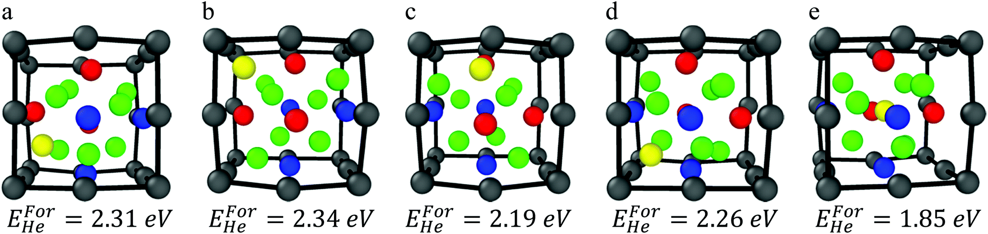 | ||
| Fig. 3 (a–d) He atom locations surrounding the oxide NC, and (e) He atom inside the oxide on the octahedral interstitial location. | ||
The interstitial locations exist along the faces and the edges of the octahedrally shaped oxide. The stable helium locations along the faces are described with respect to the oxide's metallic species that are located at the vertices of the octahedron as follows:
• He coordinated by two Ti atoms and one Y atom
• He coordinated by three Ti atoms (this corresponds to the tetrahedral interstitial position in the bulk oxide)
• He coordinated by three Y atoms
The stable helium location along the edges is described with respect to the oxide's metallic species located at the corresponding vertices of the octahedron as:
• He coordinated by two Y atoms
The formation energy for of each stable helium location has been calculated. Each of the interstitial positions in their relaxed configurations and the respective formation energy are shown in Fig. 3(a)–(e). Each of the helium defect formation energies for positions located at the oxide–Fe boundary are within ∼0.1 eV showing that the stability of helium at the boundary in different positions is roughly equivalent. The most stable helium location is at the octahedral interstitial position inside the oxide, which is incidentally where the distance between helium and Fe is maximized. In addition, previous investigations of the bulk oxide have shown that the surrounding oxygen atoms play a key role in deeply trapping the interstitial helium at the octahedral sites.21–23
The most stable helium interstitial location in BCC Fe has been previously calculated by Fu et al. as the tetrahedral interstitial location with a formation energy of 4.38 eV.26 The formation energy of a helium interstitial, placed at a tetrahedral interstitial location at the farthest point from the embedded NC, was investigated within the supercell for comparison and the resulting formation energy is 4.67 eV, confirming that helium is significantly more stable in the oxide NC and at the oxide outer boundary than in the BCC Fe.
Yang et al.23 reported first-principles investigations for accumulating quantities of helium in the bulk Y2Ti2O7 structure revealing that clusters of two helium interstitials in the bulk oxide was significantly more stable than a single helium atom in BCC Fe (where the formation energies for helium defects are EForHe = ∼2–2.5 eV in the oxide compared to EForHe = ∼4.5 eV in BCC Fe). The most stable configuration was for two helium interstitials on separate sites. However, even the configuration where a 2 He atom cluster is centered around an octahedral interstitial site (EForHe = 2.87 eV in the oxide) is significantly more stable than a single He atom in Fe. In the current computational setup, only one octahedral interstitial position exists. Thus, to investigate the stability of a small helium cluster on the most stable interstitial location, two helium interstitials (∼1.5 at%) have been initially centered on the octahedral interstitial position and relaxed to their stable positions. The relaxed structure is depicted in Fig. 4 and shows that an oxygen atom is ejected from the center of the oxide NC and becomes an interstitial located at the octahedral position in Fe, which is the most stable interstitial position for O in Fe. In addition, one helium atom remains at the central octahedral location, while the other finds its lowest energy position at the facet of the oxide. The associated formation energy is 4.1 eV. The ejection of the O atom, and the rearranging of the helium atoms to be on separate sites, is likely related to the small size of the oxide NC in the current setup and not related to the stability of the NC itself. However, in larger NCs the ejection of a boundary O atom can be a boundary effect, allowed by the available space for atoms to move at the iron/NC boundary.
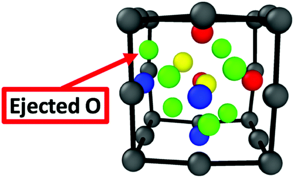 | ||
| Fig. 4 The fully relaxed structure of the embedded oxide NC with two helium interstitials initially centered around the oxide's octahedral interstitial location. | ||
A comparison of the energetics of the small two He atom cluster initially centered on the octahedral site (shown in Fig. 4) with the energetics of two He atoms placed at the boundary layer on separate sites has been made. The formation energy when the two He atoms are located on boundary sites is approximately 0.3 eV higher than the case shown in Fig. 4. This energy difference is approximately the same as the difference between the formation energy of single He interstitials, when placed on the octahedral site and at the boundary layer. This result reinforces the idea that He is most preferentially trapped within the oxide and not at the boundary layers.
The charge density and electron localization function (ELF) are shown in Fig. 5 and provide insight to the electronic structure of the oxide NC embedded in Fe. The localized maxima in the charge density correspond to atomic nuclei and core electrons. The ELF quantifies the probability of finding two electrons in close proximity to one another and thus, low values of the ELF correspond to low electron localization (or possibly no charge) and high values of the ELF correspond to highly localized regions of charge. In regions corresponding to the Fe matrix, there exists a highly homologous charge density and low electron localization, consistent with a metallically bonded crystal. By comparison, the region of the charge density corresponding to the oxide NC contains spatially expansive regions of very low charge density, and coupled with the electron localization, it is shown that little to no charge is present in the intermediate regions of the crystal that corresponds to free volume in bulk Y2Ti2O7. This is highly representative of the more localized bonding arising from the iono-covalent Y–O and Ti–O bonds present in the oxide NC.
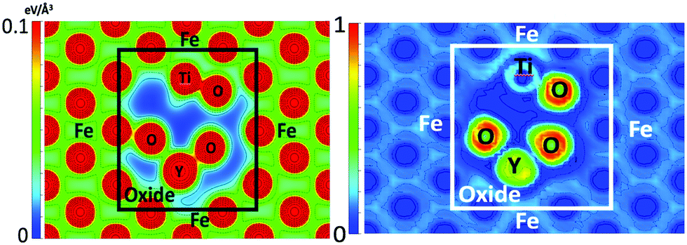 | ||
| Fig. 5 Charge density (left) and ELF (right) in the (1 −1 0) plane of the Fe containing NC supercell. | ||
The charge density and ELF when a helium atom is located at the outer boundary and at the octahedral interstitial location of the oxide NC are shown in Fig. 6. In both cases, the helium interstitial is occupying the region of very low charge density as identified in Fig. 5. Similar behavior is seen compared to what was shown in a previous DFT study21 of helium in the bulk oxide, where the interaction between He and the constituent O atoms of the oxide at the octahedral interstitial location is electron–electron repulsion, as shown by the ELF. At the tetrahedral location, there is an apparent balancing between the electron–electron repulsions of the He atom and the electron gas of the metallically bonded Fe, and with the valance shells of the neighboring O atoms of the oxide. Thus, the tetrahedral interstitial location of the oxide (which is a vacant site in the pyrochlore structure) offers a significant amount of free volume for helium to exist. Similar results are seen for each of the interstitial locations surrounding the oxide where interstitial formation is relatively favorable (compared to Fe) due to the free space at each of the locations.
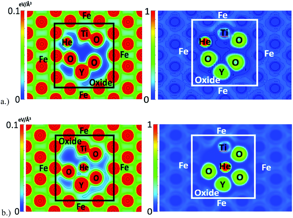 | ||
| Fig. 6 Charge density (left) an ELF (right) with helium located at (a) (top) the tetrahedral interstitial location at the outer boundary of the oxide and (b) (bottom) the octahedral interstitial location of the oxide NC. | ||
B. Mapping of the helium potential energy landscape
In order to further investigate the root cause of helium trapping at the Y2Ti2O7–Fe boundary, a mapping of the potential energy landscape has been created and compared to the charge density and ELF shown in Fig. 5.The potential energy landscape for the (1 −1 0) plane of the oxide NC embedded in Fe, as well as along the (1 0 0) plane of BCC Fe are shown in Fig. 7. The (1 0 0) plane of Fe is used because it forms the boundary with the Oxide NC. Both potential energy landscapes have been calculated using the same supercell, where the Fe part is taking place far removed from the NC. Hence, they share the same energy reference, which allows us to compare not only diffusion barriers, but also the energy at the bottom of the potential energy wells. By comparing the extrema of the potential energy landscape calculations, it is shown that (i) the potential energy maxima are larger in the oxide NC than in Fe, and (ii) the potential energy minima are lower in the oxide NC than in Fe. The maxima are localized at atomic positions corresponding to Y, Ti, and O atoms, with Y being the most extreme. The potential energy minima that exist within BCC Fe are located at the tetrahedral interstitial locations, which has been previously calculated as the most stable He interstitial position in BCC Fe.26 Although the potential energy maxima are higher in the oxide NC, regions exist where there are potential energy wells whose spatial extent is significantly larger than those present in BCC Fe. In addition, the wells are approximately 4 eV deeper in the Oxide NC than in Fe. The large spatial extent and increased well depth in the oxide makes the NC a highly energetically favorable location for helium to accumulate.
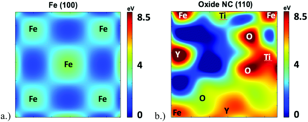 | ||
| Fig. 7 Potential energy landscape in the (a) (1 0 0) plane of BCC Fe and (b) (1 −1 0) plane of the oxide NC embedded in BCC Fe. Approximate locations of atomic species in the immediate vicinity of potential energy maxima are labeled. Both potential energy landscapes have been calculated in the same supercell, and both plot have the same energy reference. | ||
IV. Discussion
The oxide NC in the current study matches the pyrochlore structure of Y2Ti2O7, however, the stoichiometry is actually Y3Ti3O7. This setup is the analogue of two situations: (i) the introduction of a high number of oxygen vacancies to the oxide, where the vacancies are nominally occupied by Fe atoms and (ii) the addition of an extra Y and Ti atom to Y2Ti2O7, where Fe atoms have been replaced by metallic atoms of the oxide. Both of these situations give the same result that the oxide NC becomes more metallic. The increased metallic species' presence at the interface would ultimately result in delocalized bonding and a corresponding delocalized charge density and shallow potential energy wells as seen in Fe. As a result, the energetic stability of interstitials at the boundary layer in the current study is lower than what would be expected in a setup where a more oxygen rich boundary was used. An increased oxygen presence would result in increased localized iono-covalent bonding and, ultimately, a more favorable potential energy landscape for helium trapping. This is consistent with Yang's et al.27 calculations of the full {100} oxide//{100} Fe interface setup, where interstitials placed at the metallically rich interface were notably less stable (and comparable in energy to the calculations in the current work) than interstitials located within the first layer of the oxide on octahedral interstitial positions.The formation energetics of helium interstitials and interfacial defects were found to be higher than those in a previous investigation.21,23 In addition, by comparison to an investigation of the Y2Ti2O7/Fe interface27 that found that the formation energetics of interfacial He defects were similar to those in the bulk oxide, the formation energies reported here are also higher. The potential reasons for this are that in the current work, a full relaxation of the supercell volume and shape was not performed in order to prevent significant distortion of the cell and to simulate the structural conditions as they would exist within the bulk alloy. Thus, there may be strain effects that are coming into play that were not present when calculations were performed on the bulk oxide. Likewise, the stoichiometry of the oxide NC deviates from Y2Ti2O7, though the pyrochlore structure is preserved and thus, the energies cannot be exactly compared between this study and the bulk oxide investigations. However, the potential energy landscapes calculated for the NC embedded in Fe and for the bulk oxide are similar, as are the interstitial He formation energies. This suggests that the energetics of the He atom in NFAs are most likely to be dominated by steric effects, and not by the exact local chemical composition: He interstitials are more stable inside or at the boundary of the oxide NC exhibiting large free volumes, rather than in BCC iron characterized by a homogeneously delocalized charge density. This result is consistent with previous findings that helium prefers to accumulate in the oxide as opposed to iron.
By investigating the potential energy landscape, the charge density, and the ELF, the favorability of Y2Ti2O7 NCs as a helium trapping site in NFAs becomes clear. Upon implantation of He into the BCC Fe matrix, interstitial formation is highly energetically unfavorable (∼4.5 eV) and the implanted species is capable of migrating with a very low energy barrier of 0.07 eV.26 The inert helium atom's high solution energy in BCC Fe stems from the small spatial extent of the potential energy minima that exist within the electron gas of the metallically bonded BCC Fe. Thus, since no bonding occurs between the inert He atom and the bulk Fe matrix, it can be inferred that the helium atom is repelled the delocalized charge density in the BCC Fe matrix until it reaches a location in which a potential energy well exists. Examination of the potential energy landscape, and relating it to the charge density, shows that regions within the alloy with a low charge density correspond to deep potential energy wells. Such regions of low charge density within NFAs could be comprised of vacancies or di-vacancies, voids, grain-boundaries, or, as investigated in the current work, oxide nanoclusters. The localized iono-covalent bonding present within the oxide NCs creates a region within the bulk that serves as a spatially expansive potential energy well located within the Fe matrix making the oxide a highly thermodynamically favorable trapping site for helium.
Previous investigation in bulk Y2Ti2O7 showed that helium migration in the structure occurs at significantly higher energies than in BCC Fe.40 The most favorable migration pathway in the bulk structure was reported to extend between octahedral positions via the so-called “O–O” interstitial configurations with a barrier of ∼0.5 eV.40 The elevated migration barrier in the oxide is attributed to the complex potential energy landscape that arises from the Y–O and Ti–O iono-covalent bonds. This is well reflected in the current investigation where the largest barriers correspond to atomic species and intermediate diffusion pathways have migration barriers on the order of ∼1–3 eV. In contrast, the barrier heights between interstitial positions shown in the BCC Fe potential energy landscape are significantly lower (i.e. ≪1 eV), in agreement with other first-principles calculations.26 The increased thermodynamic stability, coupled with the increased migration barriers in the oxide, clearly demonstrate the synergy between the thermodynamics and kinetics to aid in trapping helium at oxide NCs. Simply put, when helium is implanted into the matrix as an alpha particle, it readily migrates through BCC Fe where it has a very low thermodynamic stability. Since there are a high number density of oxide NCs, the probability that the diffusion pathway intersects with an oxide NC is high. When the helium atom reaches an oxide NC, it reaches a more thermodynamically stable location and is less able to migrate from this location, thus remaining trapped at the oxide NC.
NFAs contain a high number density of oxide NCs of varying compositions, such as Y2O3, Y2TiO5 and other Y–Ti–O non-stoichiometric compounds. Previous DFT investigations of helium in bulk Y2O3 and Y2TiO5 exhibit remarkably similar behavior to that of helium in Y2Ti2O7 and would presumably have a potential energy landscape within Fe of a similar nature. Thus, the high number density of oxide nanoclusters within the alloy creates a high number density of potential energy wells that prevent helium from reaching grain boundaries and voids, ultimately lowering the threat of swelling, cracking and embrittlement significantly. Localized iono-covalent bonding is characteristic of oxides and thus, it can be inferred that this trapping behavior would be exhibited by a wide array of oxide compositions. The key component to preventing helium from reaching grain boundaries is to have a secondary phase that provides spatially expansive potential and deep energy wells, but also elevated migration barriers, as exhibited by the high number densities of oxide nanoclusters in NFAs. Knowing that the substantial difference in the electronic structure of the oxide and Fe creates a high number density of potential energy wells within the alloy opens the door for the investigation of alternative precipitate phases that may aid in addressing the challenges still posed by NFAs, such as the formability of large-scale reactor components.
V. Conclusions
The formation energetics and potential energy landscape of helium at a structure matched Y2Ti2O7 oxide nanocluster embedded in BCC Fe was investigated using DFT. The investigation revealed that the potential energy landscape in the oxide has a spatially extensive and deep potential energy-well and elevated migration barriers that make helium trapping favorable. The potential energy-well arises due to localized iono-covalent bonding between the metal and oxygen atoms within the oxide. From this, the pronounced ability of oxide NCs within NFAs to act as trapping sites for helium is attributed to a high number density of potential energy-wells such as that found in this investigation.Acknowledgements
The authors would like to acknowledge Advanced Research Computing at Virginia Tech for providing computational resources and technical support that have contributed to the results presented in this paper.References
- H. Trinkaus and B. N. Singh, J. Nucl. Mater., 2003, 323, 229–242 CrossRef CAS.
- M. R. Gilbert, S. L. Dudarev, D. Nguyen-Manh, S. Zheng, L. W. Packer and J. C. Sublet, J. Nucl. Mater., 2013, 442, S755–S760 CrossRef CAS.
- M. J. Alinger, G. R. Odette and D. T. Hoelzer, J. Nucl. Mater., 2004, 329–333(Part A), 382–386 CrossRef CAS.
- R. L. Klueh, P. J. Maziasz, I. S. Kim, L. Heatherly, D. T. Hoelzer, N. Hashimoto, E. A. Kenik and K. Miyahara, J. Nucl. Mater., 2002, 307–311(Part 1), 773–777 CrossRef CAS.
- D. A. McClintock, D. T. Hoelzer, M. A. Sokolov and R. K. Nanstad, J. Nucl. Mater., 2009, 386–388, 307–311 CrossRef CAS.
- P. Miao, G. Odette, T. Yamamoto, M. Alinger and D. Klingensmith, J. Nucl. Mater., 2008, 377, 59–64 CrossRef CAS.
- G. R. Odette, M. J. Alinger and B. D. Wirth, Annu. Rev. Mater. Res., 2008, 38, 471–503 CrossRef CAS.
- J. H. Schneibel, M. Heilmaier, W. Blum, G. Hasemann and T. Shanmugasundaram, Acta Mater., 2011, 59, 1300–1308 CrossRef CAS.
- S. Ukai, T. Nishida, H. Okada, T. Okuda, M. Fujiwara and K. Asabe, J. Nucl. Sci. Technol., 1997, 34, 256–263 CrossRef CAS.
- M. K. Miller, K. F. Russell and D. T. Hoelzer, J. Nucl. Mater., 2006, 351, 261–268 CrossRef CAS.
- Y. Wu, E. M. Haney, N. J. Cunningham and G. R. Odette, Acta Mater., 2012, 60, 3456–3468 CrossRef CAS.
- H. Kishimoto, M. J. Alinger, G. R. Odette and T. Yamamoto, J. Nucl. Mater., 2004, 329–333(Part A), 369–371 CrossRef CAS.
- S. Yamashita, K. Oka, S. Ohnuki, N. Akasaka and S. Ukai, J. Nucl. Mater., 2002, 307–311(Part 1), 283–288 CrossRef CAS.
- M. C. Brandes, L. Kovarik, M. K. Miller, G. S. Daehn and M. J. Mills, Acta Mater., 2012, 60, 1827–1839 CrossRef CAS.
- T. Hayashi, P. M. Sarosi, J. H. Schneibel and M. J. Mills, Acta Mater., 2008, 56, 1407–1416 CrossRef CAS.
- J. H. Schneibel, C. T. Liu, M. K. Miller, M. J. Mills, P. Sarosi, M. Heilmaier and D. Sturm, Scr. Mater., 2009, 61, 793–796 CrossRef CAS.
- Q. Li, C. M. Parish, K. A. Powers and M. K. Miller, J. Nucl. Mater., 2014, 445, 165–174 CrossRef CAS.
- P. D. Edmondson, C. M. Parish, Y. Zhang, A. Hallén and M. K. Miller, Scr. Mater., 2011, 65, 731–734 CrossRef CAS.
- P. D. Edmondson, C. M. Parish, Y. Zhang, A. Hallén and M. K. Miller, J. Nucl. Mater., 2013, 434, 210–216 CrossRef CAS.
- G. R. Odette, P. Miao, D. J. Edwards, T. Yamamoto, R. J. Kurtz and H. Tanigawa, J. Nucl. Mater., 2011, 417, 1001–1004 CrossRef CAS.
- T. Danielson and C. Hin, J. Nucl. Mater., 2014, 452, 189–196 CrossRef CAS.
- T. Danielson, E. Tea and C. Hin, J. Phys. D: Appl. Phys., 2016, 49, 065301 CrossRef.
- L. Yang, Y. Jiang, G. Robert Odette, T. Yamamoto, Z. Liu and Y. Liu, J. Appl. Phys., 2014, 115, 143508 CrossRef.
- P. Erhart, J. Appl. Phys., 2012, 111, 113502 CrossRef.
- Y. Jin, Y. Jiang, L. Yang, G. Lan, G. Robert Odette, T. Yamamoto, J. Shang and Y. Dang, J. Appl. Phys., 2014, 116, 143501 CrossRef.
- C.-C. Fu and F. Willaime, Phys. Rev. B: Condens. Matter Mater. Phys., 2005, 72, 064117 CrossRef.
- L. Yang, Y. Jiang, Y. Wu, G. R. Odette, Z. Zhou and Z. Lu, Acta Mater., 2016, 103, 474–482 CrossRef CAS.
- L. Barnard, G. R. Odette, I. Szlufarska and D. Morgan, Acta Mater., 2012, 60, 935–947 CrossRef CAS.
- C. L. Fu, M. Krčmar, G. S. Painter and X.-Q. Chen, Phys. Rev. Lett., 2007, 99, 225502 CrossRef CAS PubMed.
- G. Kresse and J. Hafner, Phys. Rev. B: Condens. Matter Mater. Phys., 1993, 47, 558–561 CrossRef CAS.
- G. Kresse and J. Hafner, Phys. Rev. B: Condens. Matter Mater. Phys., 1994, 49, 14251–14269 CrossRef CAS.
- G. Kresse and J. Furthmüller, Comput. Mater. Sci., 1996, 6, 15–50 CrossRef CAS.
- G. Kresse and J. Furthmüller, Phys. Rev. B: Condens. Matter Mater. Phys., 1996, 54, 11169–11186 CrossRef CAS.
- P. E. Blöchl, Phys. Rev. B: Condens. Matter Mater. Phys., 1994, 50, 17953–17979 CrossRef.
- G. Kresse and D. Joubert, Phys. Rev. B: Condens. Matter Mater. Phys., 1999, 59, 1758–1775 CrossRef CAS.
- J. P. Perdew, K. Burke and M. Ernzerhof, Phys. Rev. Lett., 1996, 77, 3865–3868 CrossRef CAS PubMed.
- J. P. Perdew, K. Burke and M. Ernzerhof, Phys. Rev. Lett., 1997, 78, 1396 CrossRef CAS.
- J. Ribis and Y. de Carlan, Acta Mater., 2012, 60, 238–252 CrossRef CAS.
- M. J. Alinger, S. C. Glade, B. D. Wirth, G. R. Odette, T. Toyama, Y. Nagai and M. Hasegawa, Mater. Sci. Eng., A, 2009, 518, 150–157 CrossRef.
- T. Danielson, E. Tea and C. Hin, J. Nucl. Mater., 2016, 477, 215–221 CrossRef CAS.
| This journal is © the Owner Societies 2016 |