
 Open Access Article
 This Open Access Article is licensed under a
 Creative Commons Attribution 3.0 Unported Licence
Preparation and structure of Fe-containing aluminosilicate thin films†
Héloïse
Tissot
,
Linfei
Li
,
Shamil
Shaikhutdinov
* and
Hans-Joachim
Freund
Department of Chemical Physics, Fritz Haber Institute, Faradayweg 4-6, 14195 Berlin, Germany. E-mail: shaikhutdinov@fhi-berlin.mpg.de
First published on 11th August 2016
Abstract
In attempts to fabricate model systems of Fe-containing aluminosilicates, we studied the incorporation of iron into silicate and aluminosilicate bilayer films grown on Ru(0001). Structural characterization was performed by low energy electron diffraction, X-ray photoelectron spectroscopy, infrared reflection-absorption spectroscopy and scanning tunneling microscopy. The experimental results show that even at low concentrations Fe does not randomly substitute Si(Al) cations in the silicate framework, but segregates into a pure silicate (aluminosilicate) phase and an Fe-silicate phase which is formed by an FeO(111)-like layer underneath a silicate layer. At high Fe/(Si + Al) molar ratios, the resulting films showed two phases depending on the annealing temperature. In both phases, the surface exposes a silicate layer and the bottom layer is dominated by FeO. The Al ions seem to be present in the bottom layer at relatively low oxidation temperatures, but segregate as alumina clusters at the surface at higher temperatures. The results suggest that the formation of in-frame Fe species in silicalites and zeolites is thermodynamically unfavourable. This study provides further steps towards the rational design of model systems for studying surface chemistry of a wide class of layered minerals.
1. Introduction
Recent progress in the preparation of thin silicate and aluminosilicate films on metal substrates opened new possibilities for experimental and theoretical studies of surface chemistry on very complex materials like zeolites and clays.1–6 Ultrathin silicate films are formed by one and/or two layers of corner-sharing SiO4 tetrahedra like in phyllosilicates. In aluminosilicate films, Al substitutes Si in the silicate framework.5 In contrast, the silicate films modified by Fe showed structural similarities to clay minerals (e.g. nontronite). More specifically, the Fe-silicate film is composed of a single silicate layer on top of the FeO(111)-like layer, which is, in turn, bonded to a Ru(0001) surface.7 Basically, the same picture has recently been observed for Ti-silicate films as well.8The reactivity of clay minerals and zeolites is often controlled by transition metal(s) present in the system. For example, Fe-containing zeolite ZSM-5 is recognized as a promising catalyst for phenol production by gas phase oxidation of benzene, although the nature of active species in zeolites remains controversial owing to a variety of Fe coordination, both in and out of the aluminosilicate frame, and their clustering.9–16 Also in clays, the oxidation state of structural Fe is known to have a great impact on their surface chemical properties.17,18 Finally, aluminosilicates in general, and zeolites in particular, are used as anti-corrosion coatings for various applications.19,20 However, to date, “surface-science” studies on such complex materials are scarce, primarily due to the lack of model systems suited for the facile application of surface sensitive techniques. Previous attempts to grow aluminosilicate (zeolitic) thin films primarily used hydrothermal synthesis.21 The prepared films had thicknesses of about several hundreds of nanometers, showed no long-range order and were polycrystalline and/or granular in nature.
In this work, we performed a comparative study of iron interaction with silicate and aluminosilicate bilayer films, previously studied in our laboratories in detail, aiming at the preparation of well-defined model systems that would allow us to elucidate possible atomic structures and chemistry of Fe-containing aluminosilicates. Structural characterization was performed by low energy electron diffraction (LEED), X-ray photoelectron spectroscopy (XPS), infrared reflection-absorption spectroscopy (IRAS) and scanning tunneling microscopy (STM).
2. Methods and materials
The experiments were carried out in an ultrahigh vacuum (UHV) chamber equipped with a LEED (from Omicron), an XPS (with a Scienta SES 200 hemispherical analyser), an IRAS (Bruker i66vs) and a STM (Omicron). The Ru(0001) crystal (99.99%, from MaTeck) was mounted on an Omicron sample holder. The temperature was measured using a Type K thermocouple spot-welded to the edge of the crystal.The clean Ru(0001) surface was obtained by repeated cycles of Ar+-sputtering and annealing to 1300 K in UHV unless no contaminations were detected by XPS. Then the surface was pre-covered with a 3O(2 × 2)-layer by exposing to 3 × 10⁻⁶ mbar O2 at 1150 K for 5 min and cooling to 500 K prior to pumping oxygen out. Silicon was vapor-deposited onto the O/Ru(0001) surface at ∼100 K in 2 × 10⁻⁷ mbar O2. For the preparation of Fe- and Al-containing films, Fe and Al were sequentially deposited after Si deposition at 100 K. For all films, the sum of the molar amounts of Si, Al and Fe was equal to the amount of Si necessary to prepare the bilayer silicate film as observed using XPS and IRAS. After low temperature deposition, final oxidation was performed in 3 × 10⁻⁶ mbar O2 at elevated temperatures as indicated in the text.
The XP spectra were referenced by setting the Au 4f7/2 level to 84.0 eV measured on a clean gold foil. The IRA spectra were recorded using p-polarized light at a grazing angle of incidence of 84° (resolution 4 cm−1). STM images were obtained at room temperature using Pt–Ir tips under tunnelling conditions as indicated in the figure captions.
3. Results and discussion
In order to prepare Fe-containing (alumino)silicates, two different approaches may be envisioned. The first one includes Fe deposition on top of the prepared silicate film. The second preparation uses co-deposition of Fe and Si (+Al) atoms followed by oxidation under the conditions, at which pure silicate films are usually formed.We first examined the interaction of Fe atoms with a silicate bilayer film. Deposition of 1 ML (1 ML = 8 × 10¹⁴ at. per cm2) of iron at low temperatures (∼100 K) showed only small changes in the IRA spectra (which are characterized by the main band at 1296 cm−1, originated from asymmetric vibrations of Si–O–Si bonds linking two silicate layers in the bilayer, and another less intense band at 692 cm−1 corresponding to bending vibrations of “in plane” siloxane bonds parallel to the film surface).3 We also used adsorbed CO and N2O as probe molecules in attempts to detect Fe atoms at the film surface. However, the adsorption experiments could not reveal Fe-related features in a conclusive manner, since small spectral changes could, in principle, be assigned to Fe partially adsorbed in holes exposed on the substrate which are present in all samples to a certain extent. On the other hand, XP spectra revealed a considerable shift of both Si 2p and O 1s core levels by ∼0.8 eV to higher binding energies, which was even observed upon Fe deposition at low temperatures (see Fig. S1 in the ESI†). Such a shift has been associated with changes in the work function of a metal substrate that, in turn, affects the alignment of the Fermi levels in the sample and the analyser.22,23 The IRAS and XPS results suggest that the Fe atoms readily migrate through the film and adsorb on a metal substrate, basically in the same manner as previously shown both theoretically and experimentally for Au and Pd atoms.24
When the Fe containing sample was subsequently oxidized at ∼800 K in oxygen ambience (∼10−7 mbar), the vibrational bands of the silicate bilayer totally disappeared, and the broad asymmetric band peaked at ∼1245 cm−1 appeared, which is characteristic of three-dimensional silica structures2,25 (Fig. 1a). STM inspection of the resulting films (Fig. 1b) showed randomly dispersed nanoparticles about 1 nm in height indicating that the films do not share the bilayer structure anymore and become, in essence, poorly defined. In particular, it is difficult to judge, whether the imaged particles are silica or iron oxide or both, and whether they are located on top of the silica film or directly bonded to a metal surface.
 | ||
| Fig. 1 (a) IRA spectra of a pure silicate bilayer film on Ru(0001) and after deposition of 0.4 ML Fe at ∼100 K and heating to 800 K in 10−7 mbar of O2. (b) Room-temperature STM image of the resulting film (tunneling parameters: bias 2 V and current 0.1 nA). | ||
Therefore, in the following preparations we only used a co-deposition method to incorporate Fe into silicate frameworks. For a direct comparison, we first investigated Fe-silicate films prepared in the same way as described previously,7i.e. Fe and Si were deposited at low temperature and then oxidized at ∼1100 K in 10−6 mbar of O2. At low Fe![[thin space (1/6-em)]](https://www.rsc.org/images/entities/char_2009.gif) :Si molar ratios (<1), the film separates into pure silicate and Fe-silicate phases. The latter is formed by a silicate layer placed on top of an FeO(111)-like layer, thus giving rise to an additional IRA band at 1003 cm−1 (Fig. 2a) assigned to the asymmetric stretching vibrations of the Si–O–Fe bonds.
:Si molar ratios (<1), the film separates into pure silicate and Fe-silicate phases. The latter is formed by a silicate layer placed on top of an FeO(111)-like layer, thus giving rise to an additional IRA band at 1003 cm−1 (Fig. 2a) assigned to the asymmetric stretching vibrations of the Si–O–Fe bonds.
 | ||
| Fig. 2 (a) IRA spectrum of an Fe-silicate film on Ru(0001) prepared at 1150 K. (b) High-resolution STM image (bias 1.5 V; current 0.16 nA) shows both pure and Fe-silicate surfaces. The latter is characterized by a strong Moiré e pattern clearly seen in the right portion of the image. To visualize a very weak Moiré-like modulation on the pristine surface, part of the image is presented with the enhanced contrast. The inset shows the LEED pattern (70 eV). The unit cell is shown. (c) Schematic representations of the pure silicate film on Ru(0001) forming a (2 × 2) structure (on the left) and of the Ru(0001)-(10 × 10)R30° coincidence structure formed by the 30°-rotated hexagonal layer with a lattice constant of 5.22 Å (on the right). The latter matches well the STM image. The corresponding superstructure cells are marked by the dashed lines. | ||
The phase separation is directly observed by STM (Fig. 2b), as the Fe-containing areas showed a Moiré pattern and were apparently higher with respect to the adjacent Fe-free surface, by about 0.7 Å, albeit depending on tunneling conditions. The height difference seems to be a pure electronic rather than a geometrical effect. Both, pure silicate and Fe-silicate, phases show a honeycomb-like structure with the same periodicity and azimuthal orientation. As observed from the LEED pattern (shown in the inset in Fig. 2b), the lattice constant of the Fe-silicate phase is smaller (∼5.25 Å) than that of the pristine silicate bilayer film (5.42 Å, i.e. Ru(0001)-(2 × 2)), and the unit cell is rotated by 30° with respect to the Ru(0001) surface lattice. In principle, any rotation of a hexagonal layer over a (111) metal surface should result in coincidence superstructures, with the long-range periodicity depending on the lattice mismatch and the rotation angle. In fact, the Moiré fingerprints are often used to refine the lattice constants of an overlayer if the latter could not be directly measured. It is easy to show that the rotation of a silicate layer with the a lattice constant of 5.42 Å by 30° over Ru(0001) will lead to a Ru(0001)-(7 × 7)R30° coincidence structure. Accordingly, reducing the lattice constant to 5.22 Å, as suggested by LEED, results in a Ru(0001)-(10 × 10)R30° superstructure, both schematically shown in Fig. 2c. Note that a pure FeO(111) film grown on Ru(0001) forms a Ru(0001)-(8 × 8) structure.26
Following these considerations, one should observe the Moiré pattern on the Fe-free, pure silicate surface as well. A closer look at the STM images of the areas between Fe-containing patches revealed, indeed, a long-range surface modulation, albeit of a very weak contrast (see Fig. 2b), that nicely fits the Ru(0001)-(10 × 10)R30° structure. Slight deviations from a perfect Moiré picture can readily be assigned to the O atoms residing on Ru underneath the film. The fact that the modulation amplitude is very low, in the range of few pm only, further supports the conclusion of the weak interaction between the bilayer silicate film and the Ru(0001) surface.3,23 Accordingly, a much larger amplitude observed on the Fe-modified surface points to its stronger interaction with a metal substrate through the formation of the Fe–O–Ru bonds accompanied by charge transfer from the metal.7
Analysis of large scale STM images showed that the Moiré protrusions on the Fe-silicate surface were well aligned with the crystallographic directions of the Ru(0001) surface thus following the structure scheme in Fig. 2c. In some cases, however, the Moiré pattern was found to be slightly (by 2–5°) rotated with respect to that on the pure silicate, as one can also see in Fig. 2b. The coexistence of several long-range superstructures is not surprising for ultrathin films. To some extent, such structural diversity is similar to the case of FeO(111) films grown on Pt(111), where the formation of slightly different superstructures was proved by spot profile analysis LEED.27 It seems plausible that the ultimate orientation of an Fe-silicate film on Ru(0001) depends on the preparation conditions and is a delicate balance between relatively strong interaction with the metal surface underneath and certain stiffness of the Si–O bonds in the resulting frameworks. It remains unclear, however, why the entire film is rotated by 30° with respect to Ru(0001), whereas the pure crystalline silicate films form an unrotated (2 × 2) structure (Fig. 2c).
Now we address the preparation of Fe-containing aluminosilicate films. To recall, the aluminosilicate films are characterized by an IRA band at 1290–1270 cm−1 (depending on the Al:Si molar ratio),5i.e. red-shifted when compared to a pure silicate. In the aluminosilicate films, LEED shows a sharp (2 × 2)-Ru(0001) pattern suggesting a high degree of crystallinity as confirmed by STM. In the following experiments, the Al/Si molar ratio determined by XPS was kept around 1/3. At such (and even lower) ratios, Al primarily substitutes Si in the bottom layer, most likely to overcome charge imbalance caused by the Si4+-to-Al3+ substitution.
We first discuss the results obtained for the films with an average composition Fe0.25Al0.2Si0.55O2, i.e. at relatively low Fe loading, Fe/(Si + Al) = 1/3 (the results at a lower amount of Fe differ solely in the signal intensity in IRA spectra and coverages measured by STM). Fig. 3a compares IRA spectra of the pure and Fe-containing aluminosilicate films. The band at 1277 cm−1 bears close similarities to that of pure aluminosilicate films, whereas the 1008 cm−1 band is very similar to the one previously obtained for the Fe-silicate films (Fig. 2a). Accordingly, LEED patterns (Fig. 3b) revealed (2 × 2) spots as in pure aluminosilicate films, and the Moiré structure previously observed for pure Fe-silicate films (see the inset in Fig. 2b). These findings suggest that Fe-containing aluminosilicate films at low Fe concentrations separate into two phases, which are, in essence, aluminosilicate and Fe-silicate.
 | ||
| Fig. 3 Structural characteristics of the Fe0.25Al0.20Si0.55O2 film prepared at 1150 K. (a) The IRA spectrum. The dashed line shows the spectrum of the pure aluminosilicate Al0.35Si0.65O2 film for comparison. (b) LEED pattern at 70 eV. The coexisting two unit cells are shown. (c and d) Large-scale and high-resolution STM images. Both structures show honeycomb-like lattices which are rotated by 30° with respect to each other. Tunneling parameters: 0.75 V and 0.24 nA (c); 0.7 V and 0.3 nA (d). | ||
These two phases are clearly distinguishable in the STM images (Fig. 3(c and d)). The areas showing an atomically flat honeycomb-like structure are virtually identical to those obtained on pure aluminosilicate films.5,28 The second phase, which appears brighter on the same terrace, shows a long-range periodic pattern, although not perfectly ordered if prepared by oxidation at 1150 K. The corresponding hexagonal unit cell is rotated by 30° with respect to the surrounding aluminosilicate phase, in full agreement with the LEED results, and as such can be assigned to the Fe-containing phase.
The film becomes better ordered upon further oxidation in 10−6 mbar O2 at higher temperatures (in this case, at 1230 K for 10 min). All diffraction spots are considerably sharper (Fig. 4b). Also the STM image in Fig. 4c shows that the Fe-containing area exhibits a much better ordered superstructure. Concomitantly, the IRA band at 1008 cm−1, associated with the Fe-containing phase, shifts to 998 cm−1 and becomes narrower (Fig. 4a). The band associated with the pure aluminosilicate phase slightly shifts to a higher frequency (1280 cm−1) and gains some intensity. Upon further increasing the oxidation temperature to 1250 K, all Fe-related features in IRAS, LEED and XPS vanish so that the resulting film becomes virtually identical to a pure aluminosilicate film. Note, however, that STM images of the latter surface (Fig. 4d) revealed a high density of tripod-shaped protrusions randomly distributed on crystalline domains, which are separated by antiphase domain boundaries.
 | ||
| Fig. 4 Comparison of (a) IRA spectra and (b) LEED patterns (all at 70 eV) of the Fe0.25Al0.2Si0.55O2 film stepwise annealed in 10−6 mbar O2 at indicated temperatures for 10 min each. The unit cells in LEED are shown. STM images of the sample oxidized at 1230 K (c) and 1250 K (d). Tunneling bias 0.6 V and current 0.28 nA (c); 1.5 V and 0.05 nA (d). | ||
In attempts to identify the distribution of Al and Fe atoms in these films, we performed adsorption of water which, in the case of aluminosilicate films, results in silanol (Si–OH) and/or bridging hydroxyls (Si–OH–Al), the latter being only formed, if Al is present in the top silicate layer.5,6 To hydroxylate the films, the samples were first exposed to 10−6 mbar of deuterated water (D2O) at low temperature (∼100 K) to form an ice-like film and then heated to 300 K to desorb the unreacted water.29Fig. 5 compares the IRA spectra obtained on the Fe-silicate Fe0.25Si0.75O2 and the Fe-aluminosilicate Fe0.25Al0.2Si0.55O2 films. Both spectra show a band at 2764 cm−1 assigned to ν(OD) stretching vibrations in terminal silanols.29,30 However, the intensity of the band substantially (by a factor of ∼5) increases, if Al is present in the film.
 | ||
| Fig. 5 IRA spectra of Fe0.25Al0.20Si0.55O2 (red) and Fe0.25Si0.75O2 films (black) after hydroxylation with D2O. | ||
The hydroxylated Fe-aluminosilicate films were further examined by STM. Similar to our previous studies on hydroxylated monolayer silicate films,31 STM images (Fig. 6) revealed isolated atomic protrusions of ∼1 Å in height, which were missing at the sample before water adsorption, and thus assigned to OD species. Those appeared only on the Fe-containing domains. Moreover, registry analysis (Fig. 6b) revealed that the protrusions are located on top of the Si atoms in the silicate layer and as such can be assigned to isolated silanols, identified by IRAS. A few considerably larger protrusions observed in these images (marked by circles) may tentatively be assigned to other OD groups, for example, geminal Si–(OD)2 silanols.
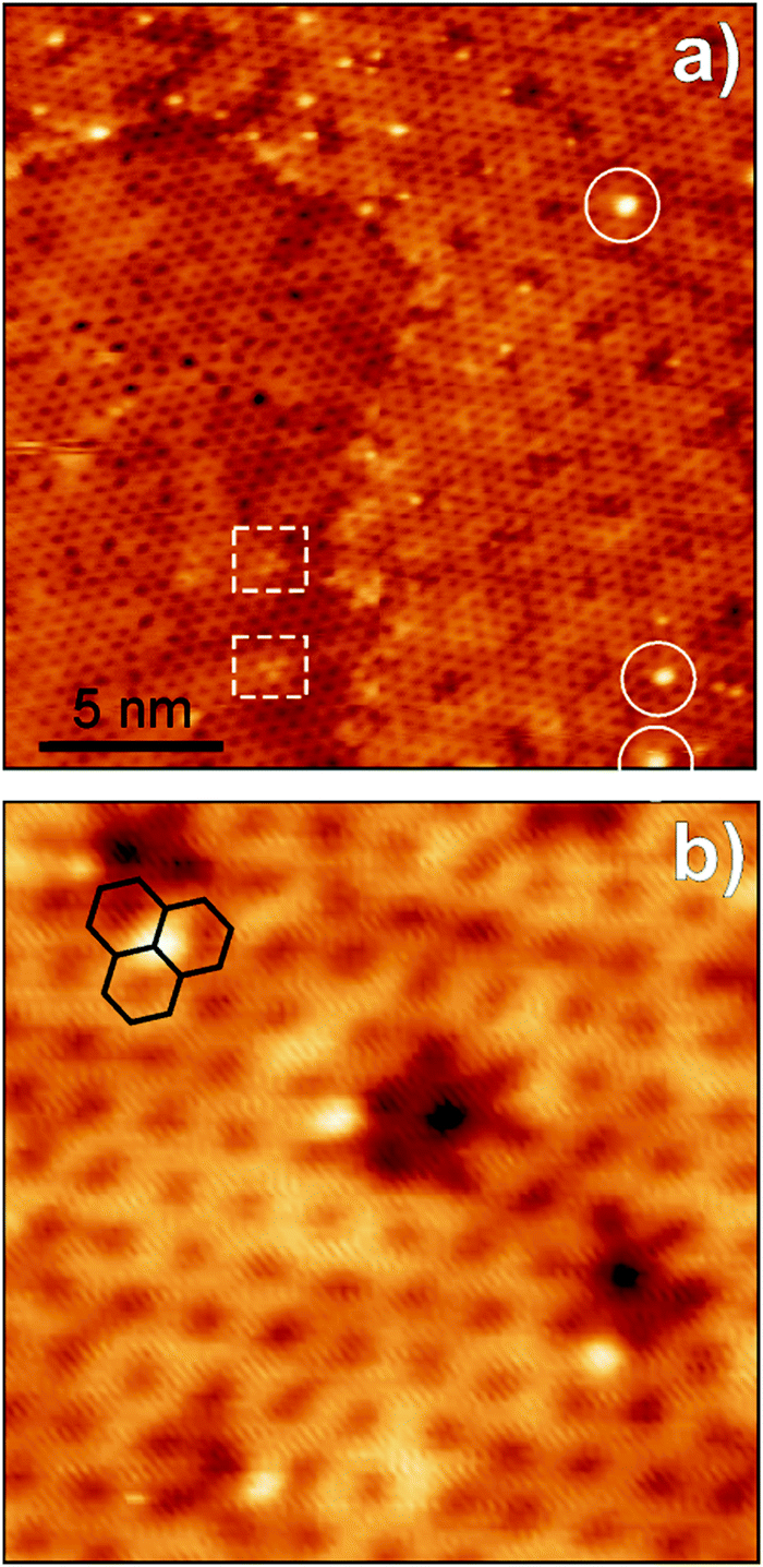 | ||
| Fig. 6 STM images of the hydroxylated Fe0.25Al0.2Si0.55O2 film prepared at 1230 K prior to the water adsorption. (Tunneling parameters: bias 1.5 V and current 0.04 nA). Image (a) reveals hydroxyl species (as bright protrusions) formed exclusively on Fe-modified areas. White circles mark a few larger protrusions tentatively assigned to geminal silanols. Outlined by rectangles are tripod species imaged in Fig. 4d prior to water adsorption. Image (b) shows that the OH-related protrusions are located on top of a Si atom in the hexagonal silicate layer (three hexagons are shown, for clarity). | ||
In principle, a low density of silanols observed in the Fe-silicate films is consistent with the proposed structure model, where Fe is preferentially located in the bottom layer, and the surface is terminated by almost a perfectly ordered silicate layer.7 Hydroxylation both on pure silicate and Fe-silicate films occurs, in essence, only on structural defects.29 However, if the Fe-containing domains in the Fe-doped aluminosilicate films were fully identical to the Fe-silicate phase, one should expect to see the same (weak) response to water, which is apparently not the case. Therefore, a considerable enhancement of silanol density on the Fe-containing domains points to the fact that the silanols are likely to form on certain sites which are modified by Al atoms present in the bottom FeO layer as an “impurity”. Fig. 6 also shows that the silanols are distributed not randomly, but in the close vicinity of the depressed spots, which form a periodic long-range structure (see also Fig. 4c). It appears that the hydroxylation occurs on specific sites within the coincidence superstructure. Noteworthily, the tripod species outlined by rectangles in Fig. 6a appear virtually identical to those in original films (Fig. 4d), thus suggesting that they are, in essence, inert towards water.
In the next set of experiments, we studied the Fe-aluminosilicate films with a considerably higher Fe content (Fe0.5Al0.13Si0.37O2) such that the amount of Fe is comparable with the total amounts of Si and Al in the film (Fe/(Si + Al) ≈ 1). After deposition of all three metals at low temperature, the samples were annealed in 10−6 mbar of O2 at elevated temparatures for 10 min.
The absence of any spectral feature in the 1250–1300 cm−1 region in the IRA spectra (Fig. 7) suggests that, at such high Fe concentrations, no pure silicate or aluminosilicate phase can be formed. The two principal bands at ∼1035 and ∼985 cm−1 fall in the range typical for an Fe-silicate phase, although both frequencies somewhat deviate from 998–1008 cm−1 measured on films with a low Fe content under similar conditions (Fig. 2 and 4). At low oxidation temperature (1050 K), the high frequency band dominates, whereas at high temperature (1250 K), the situation turns to opposite. Concomitantly, the similar changes are observed for bending modes in the 670–690 cm−1 region. The transition is not reversible, i.e. re-oxidation at low temperature of the film that has been once oxidized at higher temperature does not result in any further spectral changes.
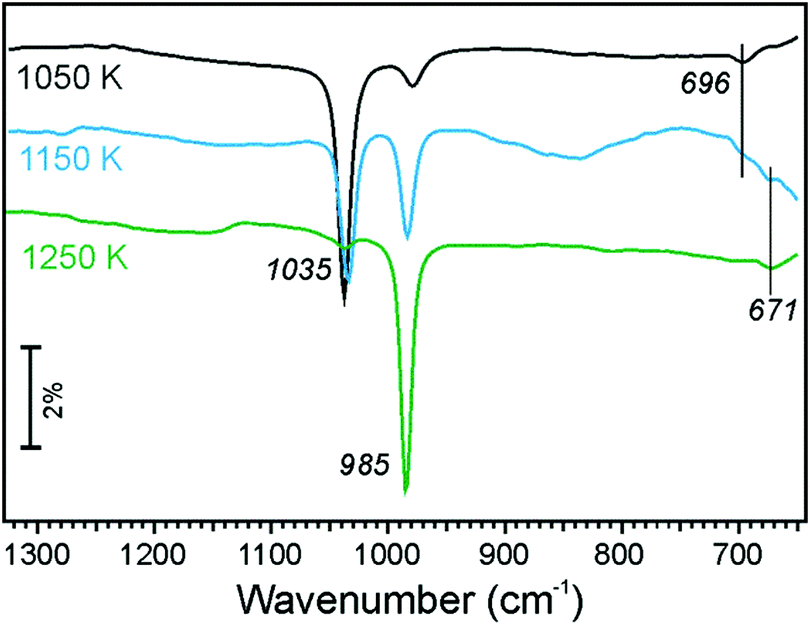 | ||
| Fig. 7 IRA spectra of the Fe0.5Al0.13Si0.37O2 film prepared by annealing in 10−6 mbar of O2 at temperatures as indicated. | ||
In agreement with IRA spectra showing no signals in the 1300–1250 cm−1 region, LEED patterns in Fig. 8(g–i) show no (2 × 2) spots corresponding to the aluminosilicate phase, which have, indeed, been observed on films with a low Fe content (Fig. 4). However, additional diffraction spots emerged, which can be identified as a (√3 × √3)R30° structure with respect to the Fe-silicate lattice. This new structure is most clearly seen on samples prepared at 1050 and 1150 K, but disappears upon oxidation at 1250 K, basically following the evolution of the 1035 cm−1 band in IRAS.
 | ||
| Fig. 8 Large-scale (a–c) and high resolution (d–f) STM images, and LEED patterns (g–i) (all at 70 eV) of the Fe0.5Al0.13Si0.37O2 films prepared by annealing in 10−6 mbar O2 at 1050 K (top row), 1150 K (middle row) and 1250 K (bottom row). The insets in (e and f) show zoomed in images (see the text). The areas with distinct surface morphologies are labelled I and II in order to correlate with the IRA bands shown in Fig. 7. Tunneling parameters: (a) 1.5 V and 0.15 nA; (b) 2 V and 0.1 nA; (c) 1 V and 0.2 nA; (d) 1 V and 0.3 nA; (e) 0.8 V (inset 0.65 V) and 0.1 nA; (f) 0.7 V (inset 0.5 V) and 0.2 nA. | ||
Again, in agreement with the IRAS results showing two bands in the ∼1000 cm−1 region, STM images revealed two surface structures, labelled I and II in Fig. 8(a–f). The structure I shows a hexagonal lattice and a long-range surface modulation as previously seen on the Fe-silicate surface. This structure dominates the surface oxidized at 1250 K and must, therefore, be associated with the 985 cm−1 band. The structure II also shows a honeycomb structure (see the inset in Fig. 8e) but on a large scale the surface is not atomically flat, albeit showing a faint long-range superstructure under some tunnelling conditions (not shown). The structure II dominates the surface prepared at 1050 K, and hence correlates with the 1035 cm−1 band. At intermediate temperatures (1150 K), both structures are equally presented at the surface.
Yet no surface structure has been identified by STM that can directly be linked to the (√3 × √3)R30° diffraction pattern. The latter corresponds to a ∼9 Å periodicity (=√3 × 5.22 Å). Based on the LEED and IRAS results, the structure must be associated with the surface II, which exhibits, however, a too much corrugated surface to be determined precisely by STM. It seems plausible that the (√3 × √3)R30° structure observed by LEED originates from the film/support interface which is not directly accessible in STM. It is also noteworthy that the structure I always showed some small clusters on top (Fig. 8f), the density of which increases at high temperatures. Such species can tentatively be assigned to the excess of deposited materials that cannot be accommodated in the bilayer film. In fact, it is difficult to precisely deposit all three metals in total amounts to form a perfect film.
To shed more light on the element (Si, Fe, Al) distribution across the film, we perfomed XPS measurements at normal and grazing (i.e. more surface sensitive) electron emissions. A relatively broad O 1s signal in these films was deconvoluted in three components on the basis of previous studies on Fe-silicate and aluminosilicate films (Fig. 9).5,7 The first component at ∼532 eV is assigned to oxygen atoms in Si–O–Si bonds, another one centered at ∼531 eV to the Si–O–Fe (Si–O–Al) bonds, and the signal at ∼530 eV to Fe–O–Fe bonds. Compared to the normal emission spectrum, the Si–O–Si associated component gains considerable intensity at grazing emission. In addition, some intensity is observed at ∼534 eV, the origin of which remains unclear. The same picture is obtained for the samples prepared at 1150 and 1250 K (Fig. S2, ESI†). Therefore, the results suggest that the topmost layer is primarily formed by the siloxane Si–O–Si network. The conclusion is further substantiated by water adsorption experiments. The IRA spectra of the hydroxylated samples only showed the band at 2764 cm−1 (Fig. S3, ESI†) assigned to terminal silanols, and no bridging hydroxyls, such as Si–OD–Al and/or Si–OD–Fe commonly observed in Fe-containing zeolites,32,33 were detected. Although the ν(OD) signal intensity slightly depends on the oxidation temperature, it is close to that observed for the pure silicate and Fe-silicate films, at variance with the Fe-aluminosilicate samples with a low Fe content where enhanced hydroxylation was clearly observed (see Fig. 5).
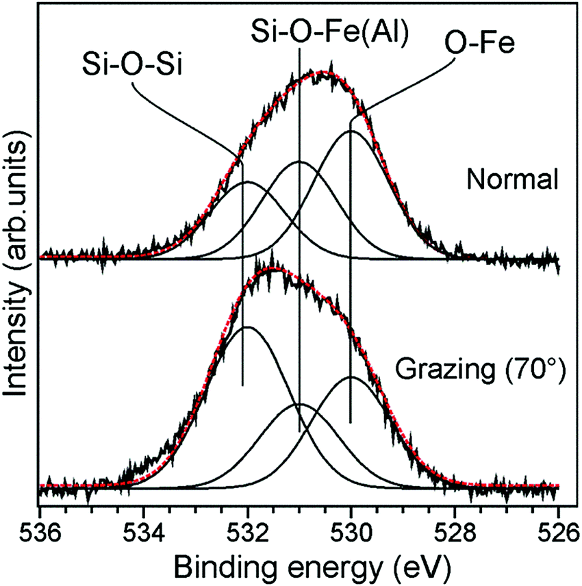 | ||
| Fig. 9 The normalised O 1s signals in XP spectra measured at normal and grazing (70°) electron emissions on the Fe0.5Al0.13Si0.37O2 film prepared at 1050 K. The deconvolution envelope is shown in red. | ||
Therefore, combined together the results for Fe-rich aluminosilicate films suggest that the films ultimately annealed at high temperature are Fe-silicate in nature. They show all fingerprints of the pure Fe-silicate film. This implies that Al, otherwise substituting Si in the bottom layer in an aluminosilicate film, is pushed out by Fe that dominates the bottom layer in all Fe-doped films. Moreover, it seems plausible that small clusters imaged on top of the well-ordered Fe-silicate surface (Fig. 8f) are, in fact, alumina clusters that could not be accommodated in the framework. However, at low oxidation temperatures, it remains possible that both Al and Fe constitute a “mixed” bottom layer, thus resulting in less-ordered domains II in STM images shown in Fig. 8 and blue-shifted IRA bands associated with Si–O–Fe(Al) bonds.
4. Conclusions
We studied the incorporation of iron into silicate and aluminosilicate bilayer films grown on Ru(0001). The results obtained by LEED, XPS, IRAS and STM show that, even at low concentrations, Fe does not randomly substitute Si(Al) cations in the silicate framework, but segregates into Fe-silicate and pure silicate (aluminosilicate) phases. The former one is formed by a silicate layer on top of an FeO(111)-like layer. At high Fe/(Si + Al) molar ratios, the resulting films showed two phases depending on the oxidation temperature. In both phases, the films are terminated by a silicate layer, whereas the bottom layer is dominated by FeO, more noticeably at high temperatures. Aluminium is probably involved in the formation of a yet poorly defined bottom layer if prepared at low temperatures (∼1050 K). However, Fe pushes out Al from the bottom layer at increasing temperatures which, in turn, segregates at the surface as an alumina cluster.The results suggest that the formation of “in frame” Fe sites in zeolites is thermodynamically unfavourable. The results again highlight the differences between the principal structures of the Fe- and Al-modified silicate films, which manifest the known differences between naturally occurring materials. While octahedrally coordinated iron is commonly found in clay minerals, tetrahedral iron substituting Si4+ in silicate frameworks is a rare case.
The results provide further steps toward rational design of model systems for studying surface chemistry of a wide class of layered minerals.
Acknowledgements
This work was supported by Deutsche Forschungsgemeinschaft through Collaborative research center SFB 1109 administrated by Humboldt University at Berlin. We also thank Anibal Boscoboinik and Xin Yu for having performed experiments at the initial stages of the project.References
- S. Shaikhutdinov and H.-J. Freund, Metal-supported aluminosilicate ultrathin films as a versatile tool for studying the surface chemistry of zeolites, ChemPhysChem, 2013, 14, 71–77 CrossRef CAS PubMed.
- S. Shaikhutdinov and H.-J. Freund, Ultrathin Silica Films on Metals: the Long and Winding Road to Understanding the Atomic Structure, Adv. Mater., 2013, 25, 49–67 CrossRef CAS PubMed.
- D. Löffler, et al., Growth and structure of crystalline silica sheet on Ru(0001), Phys. Rev. Lett., 2010, 105, 146104 CrossRef PubMed.
- L. Lichtenstein, et al., The Atomic Structure of a Metal-Supported Vitreous Thin Silica Film, Angew. Chem., Int. Ed., 2012, 51(2), 404–407 CrossRef CAS PubMed.
- J. A. Boscoboinik, et al., Modeling Zeolites with Metal-Supported Two-Dimensional Aluminosilicate Films, Angew. Chem., 2012, 51, 6005–6008 CrossRef CAS PubMed.
- J. A. Boscoboinik, et al., Interaction of Probe Molecules with Bridging Hydroxyls of Two-Dimensional Zeolites: A Surface Science Approach, J. Phys. Chem. C, 2013, 117(26), 13547–13556 CAS.
- R. Włodarczyk, et al., Atomic Structure of an Ultrathin Fe-Silicate Film Grown on a Metal: A Monolayer of Clay?, J. Am. Chem. Soc., 2013, 135(51), 19222–19228 CrossRef PubMed.
- F. D. Fischer, et al., Ultrathin Ti-Silicate Film on a Ru(0001) Surface, J. Phys. Chem. C, 2015, 119(27), 15443–15448 CAS.
- G. I. Panov, Advances in oxidation catalysis: Oxidation of benzene to phenol by nitrous oxide, CATTECH, 2007, 18–31 Search PubMed.
- G. I. Panov, et al., Oxidation of Benzene to Phenol by Nitrous Oxide over Fe-ZSM-5 Zeolites, Appl. Catal., A, 1992, 82, 31–36 CrossRef CAS.
- M. Gubelmann and P.-J. Tirel, Preparation of Phenol by Direct Hydroxylation of Benzene, 1988 Search PubMed.
- K. A. Dubkov, et al., Evolution of Iron States and Formation of α-Sites upon Activation of FeZSM-5 Zeolites, J. Catal., 2002, 207, 341–352 CrossRef CAS.
- L. J. Lobree, et al., Investigations of the State of Fe in H-ZSM-5, J. Catal., 1999, 186, 242–253 CrossRef CAS.
- A. Zecchina, et al., Structure and Nuclearity of Active Sites in Fe-zeolites: Comparison with Iron Sites in Enzymes and Homogeneous Catalysts, Phys. Chem. Chem. Phys., 2007, 9, 3483–3499 RSC.
- G. Berlier, et al., Evolution of Extraframework Iron Species in Fe Silicalite, J. Catal., 2002, 208, 64–82 CrossRef CAS.
- G. I. Panov, et al., Iron complexes in zeolites as a new model of methane monooxygenase, React. Kinet. Catal. Lett., 1997, 61(2), 251–258 CrossRef CAS.
- J. W. Stucki, Properties and behaviour of iron in clay minerals, Developments in Clay Science, 2013, pp. 559–611 Search PubMed.
- J. Cervini-Silva, et al., Adsorption kinetics of pentachlorethane by iron-bearing smectites, Clays Clay Miner., 2000, 48(1), 132–138 CAS.
- P. Banerjee, et al., Influence of Zeolite Coating on the Corrosion Resistance of AZ91D Magnesium Alloy, Materials, 2014, 7(8), 6092–6104 CrossRef CAS.
- P. V. Krivenko and S. G. Guziy, Aluminosilicate coatings with enhanced heat- and corrosion resistance, Appl. Clay Sci., 2013, 73, 65–70 CrossRef CAS.
- T. Bein, Synthesis and Applications of Molecular Sieve Layers and Membranes, Chem. Mater., 1996, 8(8), 1636–1653 CrossRef CAS.
- B. Yang, S. Shaikhutdinov and H.-J. Freund, Ultrathin silicatene/silicon-carbide hybrid film on a metal substrate, Surf. Sci., 2015, 632, 9–13 CrossRef CAS.
- R. Włodarczyk, et al., Tuning the electronic structure of ultrathin crystalline silica films on Ru(0001), Phys. Rev. B: Condens. Matter Mater. Phys., 2012, 85(8), 085403 CrossRef.
- C. Büchner, et al., Adsorption of Au and Pd on Ruthenium-Supported Bilayer Silica, J. Phys. Chem. C, 2014, 118(36), 20959–20969 Search PubMed.
- B. Yang, et al., Thin Silica Films on Ru(0001): Monolayer, Bilayer and Three-Dimensional Networks of SiO4 Tetrahedra, Phys. Chem. Chem. Phys., 2012, 14, 11344–11351 RSC.
- G. Ketteler and W. Ranke, Heteroepitaxial Growth and Nucleation of Iron Oxide Films on Ru(0001), J. Phys. Chem. B, 2003, 107(18), 4320–4333 CrossRef CAS.
- M. Ritter, W. Ranke and W. Weiss, Growth and structure of ultrathin FeO films on Pt(111) studied by STM and LEED, Phys. Rev. B: Condens. Matter Mater. Phys., 1998, 57(12), 7240–7251 CrossRef CAS.
- J. A. Boscoboinik, et al., Building blocks of zeolites on an aluminosilicate ultra-thin film, Microporous Mesoporous Mater., 2013, 165, 158–162 CrossRef CAS.
- B. Yang, et al., Hydroxylation of Metal-Supported Sheet-Like Silica Films, J. Phys. Chem. C, 2013, 117(16), 8336–8344 CAS.
- X. Yu, et al., Electron stimulated hydroxylation of a metal supported silicate film, Phys. Chem. Chem. Phys., 2016, 18(5), 3755–3764 RSC.
- B. Yang, S. Shaikhutdinov and H.-J. Freund, Tuning Spatial Distribution of Surface Hydroxyls on a Metal-Supported Single-Layer Silica, J. Phys. Chem. Lett., 2014, 5(10), 1701–1704 CrossRef CAS PubMed.
- S. Bordiga, et al., Structure and Reactivity of Framework and Extraframework Iron in Fe-Silicate as Investigated by Spectroscopic and Physicochemical Methods, J. Catal., 1996, 158(48), 486–501 CrossRef CAS.
- A. Zecchina, et al., Infrared studies of the interaction of carbon monoxide and dinitrogen with ferrisilicate MFI-type zeolites, Catal. Lett., 1996, 42(1), 25–33 CrossRef CAS.
Footnote |
| † Electronic supplementary information (ESI) available. See DOI: 10.1039/c6cp03460h |
| This journal is © the Owner Societies 2016 |