
 Open Access Article
 This Open Access Article is licensed under a Creative Commons Attribution-Non Commercial 3.0 Unported Licence
Energy barriers and mechanisms in solid–solid polymorphic transitions exhibiting cooperative motion†
Joost A.
van den Ende
a,
Bernd
Ensing
b and
Herma M.
Cuppen
*a
aInstitute for Molecules and Materials, Radboud University Nijmegen, Heyendaalseweg 135, 6525 AJ Nijmegen, The Netherlands. E-mail: h.cuppen@science.ru.nl
bVan't Hoff Institute for Molecular Sciences, University of Amsterdam, Science Park 904, 1098 XH Amsterdam, The Netherlands
First published on 21st April 2016
Abstract
Understanding solid–solid polymorphic transitions within molecular crystals on the molecular scale is a challenging task. It is, however, crucial for the understanding of transitions that are thought to occur through cooperative motion, which offer an interesting perspective for future applications. In this paper, we study the energy barriers and mechanisms involved in the β → α DL-norleucine transition at the molecular scale by applying different computational techniques. We conclude that the mechanism of the transition is a cooperative movement of bilayers through an intermediate state. The results indicate that local fluctuations in the conformations of the aliphatic chains play a crucial role in keeping the cooperative mechanism sustainable at large length scales. We have characterized the intermediate state.
1 Introduction
When a molecular compound is able to crystallize in multiple crystal structures, it exhibits polymorphism.1 The different crystal structures are called polymorphic forms. These polymorphic forms can have different properties, which is especially relevant in a pharmaceutical context, e.g. the recent discovery of the effect of polymorphism on the solubility of thyroxine.2 Control of polymorphic forms is challenging, which is reflected by severe difficulties in obtaining a desired polymorphic form3,4 in certain cases.A part of this challenge is contained in understanding polymorphic transitions within the solid state.5 Inhibiting these transitions could extend the shelf-life of pharmaceutical polymorphic forms. On the other hand solid–solid polymorphic transitions can lead to spectacular and potentially useful mechanical responses.6 If these responses occur under the influence of heating or cooling, one speaks of thermosalient materials.
Polymorphic transitions are driven by a free energy difference. If the relative stability of different polymorphic forms changes reversibly as a function of temperature, one speaks of enantiotropically related polymorphic forms. In the case of transformations in which the parent and daughter phase have similar structures, there is an ongoing debate on whether the transformation mechanism is martensitic or occurs through nucleation and growth.5,7,8 A martensitic transition is a first-order displacive and cooperative solid-to-solid transition that proceeds without atom diffusion and with homogeneous lattice deformation.6,9 A true martensitic transition with fully concerted motion would result in an instantaneous transition. For many thermosalient materials that are thought to exhibit cooperative phase transitions, the transition is indeed fast (in the millisecond range) and the near instantaneous transition releases a considerable amount of free energy that is converted into mechanical work. To date, most information on transitions in molecular crystals is inferred from X-ray structures before and after the phase transition. Such an approach does not consider the transition mechanism involved and, e.g., ignores the possibility of the transition pathways deviating from the direct line between the initial and final structure.
The α ↔ β polymorphic transition of DL-norleucine10 serves as an excellent model system to study phase transitions in molecular crystals that exhibit martensitic behaviour. The α11 and β12 polymorphic forms are very similar. The conformation of the molecule forming the asymmetric unit is the same in both phases, which are composed of hydrogen-bonded bilayers being linked together by weakly van-der-Waals bonded side chains. The difference lies in the orientation of the bilayers with respect to each other. This is visualized by the two different colors in Fig. 1, which differentiate between the D and L enantiomer. Within the two forms the relative orientations are different, the difference being a shift of half a unit cell in both the a and the b-direction. Hence, the transition might involve two shifts in perpendicular directions, which results in three different routes as schematically depicted in Fig. 2: one direct route and two routes with intermediate states (I1 and I2). Using molecular dynamics simulations we have observed these two intermediate states. Layers easily slide along the b-directions starting from both the α form leading to I1 (unpublished results) or β form resulting in I2.13
 | ||
| Fig. 1 Overview of the β (top side of the figure) and α (bottom side of the figure) polymorphic forms. Shown are the ac and the bc-plane. Molecules coloured per element are part of the unit cell. Uniformly coloured molecules are of the same chirality. On the interfaces of the hydrogen-bonded bilayers this colouring helps to note the differences between the polymorphic forms, which consist of shifts in both the b and the a-direction. | ||
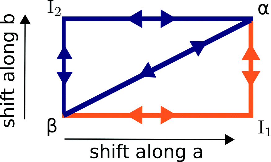 | ||
| Fig. 2 A schematic overview of the three possible routes, direct and along a and b, that lead to a transition from the β to the α. The most likely route as obtained from an earlier study14 is depicted in orange. | ||
In a previous study we employed nudged elastic band (NEB) calculations to assess the most likely mechanism.14 The only constraints were the initial and final configurations for each of the five paths in the figure and the method is allowed to freely probe different routes between them. The most likely mechanism turned out to be a two-step cooperative mechanism through I1, indicated in orange in Fig. 2 and we obtained barriers for all steps.
At this point, we would like to stress that Fig. 2 is only a schematic representation. It does not say anything about the mechanism of these shifts, which can either occur through cooperative motion or by a spreading mechanism where individual molecules move one at a time in a “zipper”-like fashion. Moreover, it does not say anything about the exact route of these shifts, they roughly progress along a or b but can also extend in the two perpendicular directions. For instance, in the molecular dynamics simulations, we observed that intermediate state I2 is formed through a shift not only along b but with a minor a component as well.13 I1 was not characterized to the same extent.
A few questions, however, remain. Since the barriers obtained were only for a particular simulation cell size, it is unclear how these barriers scale with cell size and whether all different routes exhibit the same scaling behaviour. If this scaling behaviour would simply be linear in the number of molecules involved, a continuation to macroscopic scales would result in enormous energy barriers at experimental length scales. The cooperative mechanism has to break down at some point. Moreover, these calculations were performed on the potential energy surface and we know that for polymorphic transitions the free energy is critical.
In the present paper, we will address this scaling behaviour and whether we can see the cooperative mechanism break down for larger cell sizes. We will further perform dynamics simulations which include temperature and entropy effects and look in more detail at the exact mechanism of transition, i.e. beyond the schematics of Fig. 2. Characterizing I1 is one of the objectives of this paper.
2 β and α polymorphic forms
As mentioned in section 1, the β and α polymorphic forms of DL-norleucine are very similar, the molecular conformations are nearly identical15 and both forms consist of hydrogen bonded bilayers of alternating chiral opposing D and L molecules, as is shown in Fig. 1. In order to facilitate the comparison between the two polymorphic forms, we have used non-standard settings for the lattice parameters as compared to the originally determined structures: for β P21/a and I2/a. Table 1 shows the lattice parameters at 200 K as obtained from MD simulations13 for the two polymorphic forms. Clearly visible is the high similarity of all cell parameters and therefore of the volume of the two different polymorphic forms. This is in contrast with the mechanically responsive materials exhibiting thermosalient behaviour, which are known to undergo large anisotropic changes6 in the cell. However, the β → α transition can be used as a model system to calculate the energy barriers of the phase transition through molecular simulation because of the high similarity between the polymorphic forms.| Polymorph | β | α | ||
|---|---|---|---|---|
| a (Å) | 10.30 ± 0.02 | 10.31 ± 0.02 | ||
| b (Å) | 4.64 ± 0.01 | 4.63 ± 0.01 | ||
| c (Å) | 32.53 ± 0.07 | 32.55 ± 0.07 | ||
| β (°) | 102.02 ± 0.26 | 102.01 ± 0.26 | ||
| V (Å3) | 1520 ± 4 | 1520 ± 4 |
3 Results
The starting coordinates of our simulations are shown in Fig. 3. They originate from a snapshot of an MD simulation of the β polymorphic form at 350 K in which no partial or full phase transitions have been observed. All calculations have been performed with periodic boundary conditions (PBC) and therefore mimic infinite crystals. This means that “scaling with size” refers to scaling with the amount of independent molecules within the simulation cell or bilayer and not to scaling with the number of molecules in a crystal, which is infinite. When studying the transition from β to α, our aim is to determine the energy barriers involved in the transition, the scaling behaviour of these energy barriers as a function of simulation cell size, the followed route (direct or via an intermediate state), and the mechanism that is governing the transition. To study this last characteristic it is important that the application of the simulation method does not a priori favour one mechanism over another. Therefore, we have only constrained 2D distances between one or two molecular pairs for the input of the simulations (see Fig. 3 and 4). These molecular pairs are part of both sides of an interface of bilayers. By using atomic distances between one or two specific molecular pairs, there is no cooperativeness assumed in the mechanisms underlying the phase transition within the length scale of the periodic box. Neighbouring molecules within or outside the bilayer are not biased and also the motion within a molecule is not forced to be cooperative, therefore the mechanism for transitions is not predetermined.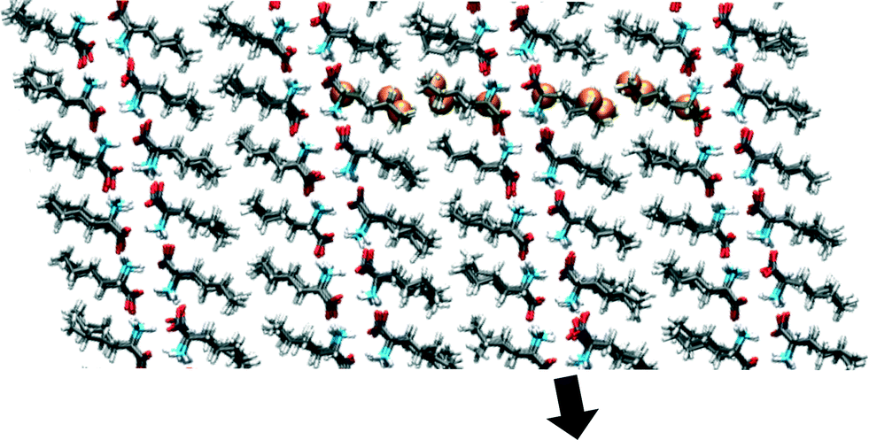 | ||
| Fig. 3 An overview of the atoms involved in the NEB, depicted as orange spheres, within the 3 × 5 × 2 simulation cell. Within the NEB calculations, the third bilayer from the left is shifted, schematically shown by the black arrow. Alongside this shift multiple images are constructed. The atoms that are connected with springs between these images are the orange spheres. The shift of this bilayer affects the two interfaces of which the bilayer is a part. For the steered MD the biasing is done directly on equivalent atom–atom distance components between one or two molecular pairs. In this way either one or two interfaces can be affected. The plane shown is the ac-plane. | ||
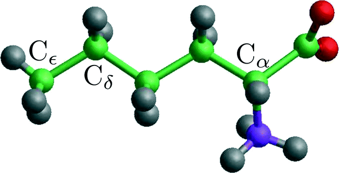 | ||
| Fig. 4 A norleucine molecule in the conformation belonging to the β and α polymorphic forms. The indicated Cα, Cδ and Cε are being used in the NEB and steered MD calculations. | ||
3.1 Nudged elastic band calculations
The nudged elastic band (NEB) method16 is a technique through which the minimum energy path of a certain process can be studied at 0 K. This is done by constructing a band of images and minimizing their energy perpendicular to the band while along the band the images are connected through springs. Convergence of this method leads to the minimum energy path (MEP). In this paper we use NEB calculations to probe energy barriers involved in the β → α solid–solid polymorphic transition of DL-norleucine. In particular, we study the scaling of the energy barriers with the size and shape of the bilayers, which gives information about the molecular mechanism of the transition.By changing the size of the studied simulation cells we probe the influence of finite-size effects on the transition. The calculations are performed at three different sizes: 6 × 5 × 2, 3 × 10 × 2, and 6 × 10 × 2. In this way, the scaling of the energy barriers can be studied in comparison with our earlier performed NEB results using 3 × 5 × 2 [31.13 Å × 23.25 Å × 66.32 Å] cells14 through a doubling of the independent molecules in both directions (a and b) within the bilayer, separately and simultaneously. This allows the study of the relative importance of these two directions. Moreover, with the larger simulation cell sizes, the distance between periodic images becomes larger, which could lead to a change in the mechanism governing the transitions. All studied cell sizes contain four bilayers. The description of the sizes refers to the number of crystalline unit cells which are located within a simulation cell.
Table 2 shows the energy barriers for the four different studied simulation cell sizes. The bold-face values in the second column indicate the barriers normalized to the number of molecules in the affected interfaces. The table shows that the 3 × 10 × 2 cell and the 6 × 5 × 2 cell give the same results and hence the barriers scale isotropically. This is a first sign of the mechanism being cooperative. A 1D or 2D “zipper” mechanism would result in a more anisotropic scaling behaviour. We further see that for most routes the barrier scales linearly with the number of molecules affected. The routes β → I1, I1 → β, I2 → α, and α → I2 deviate from this perfect linear scaling behaviour and in all four cases the proportionality appears to decrease with the number of molecules. For now we first consider the consequences of this linear scaling and we return to these deviations towards the end of the section.
| 3 × 5 × 2 | 6 × 5 × 2 | 3 × 10 × 2 | 6 × 10 × 2 | |||||
|---|---|---|---|---|---|---|---|---|
| β → α | 104.0 | 0.87 | 205.6 | 0.86 | 205.6 | 0.86 | 411.2 | 0.86 |
| β → I1 | 75.2 | 0.63 | 139.0 | 0.58 | 138.2 | 0.58 | 270.5 | 0.56 |
| I1 → α | 7.7 | 0.06 | 14.9 | 0.06 | 14.9 | 0.06 | 29.5 | 0.06 |
| β → I2 | 46.0 | 0.38 | 89.5 | 0.37 | 89.5 | 0.37 | 177.5 | 0.37 |
| I2 → α | 100.2 | 0.83 | 186.0 | 0.78 | 185.0 | 0.77 | 354.5 | 0.74 |
| α → β | 95.3 | 0.79 | 186.9 | 0.78 | 187.0 | 0.78 | 374.1 | 0.78 |
| α → I1 | 50.4 | 0.42 | 99.7 | 0.41 | 99.7 | 0.42 | 199.9 | 0.42 |
| I1 → β | 24.8 | 0.21 | 40.5 | 0.17 | 39.8 | 0.17 | 73.0 | 0.15 |
| α → I2 | 92.0 | 0.77 | 168.0 | 0.70 | 166.7 | 0.69 | 319.2 | 0.66 |
| I2 → β | 47.2 | 0.39 | 92.3 | 0.38 | 92.3 | 0.38 | 182.9 | 0.38 |
A consequence of linear scaling is that the most likely route remains the same for all sizes. This would be via I1. On this route the highest and therefore rate limiting energy barrier is lower than the direct shift of the bilayer in both directions (the diagonal in Fig. 2) or the route through I2. Although the most likely route is through I1, a shift along b has the lowest energy barrier starting from β and similarly for α. This agrees with the findings of unbiased molecular modelling studies13,17–20 that only observe shifts along this direction.
Another consequence of the linear scaling is that the overall barrier of the transition becomes very large. Although the amount of available thermal energy scales linearly with the number of molecules as well, all this thermal kinetic energy needs to accumulate to movement in the same direction in order to induce a transition. This accumulation will become increasingly less likely for larger systems.
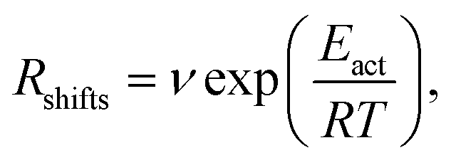
Indeed earlier molecular dynamics simulations14 showed that the β ↔ I2 transitions become less frequent with increasing simulation cell size. The present results which show linear isotropic scaling, triggered a reanalysis of these molecular dynamics simulations. In these simulations, no bias was applied and only shifts along b (β ↔ I2) could be observed. For simulations that showed multiple shifts within the simulation time, we determined the shifting rate per bilayer. These are plotted in Fig. 5 as a function of molecules in the bilayers. The circle is the rate based on a single shift. Multiple points can be observed for 40 and 60 molecules in the bilayer, which is because of variation in c length. The disagreement for 60 molecules in the bilayer could perhaps be explained by a lack of statistics since they are based on a small number of transitions. This does, however, not hold for 40 molecules in the bilayer and here this disagreement has to indicate that the scaling is not completely isotropic, when increasing the c length. Let us now assume that the shifts can be described by an Arrhenius law
 | (1) |
 | (2) |
 . Using our NEB results in Table 2 we can make an estimation for the slope
 | (3) |
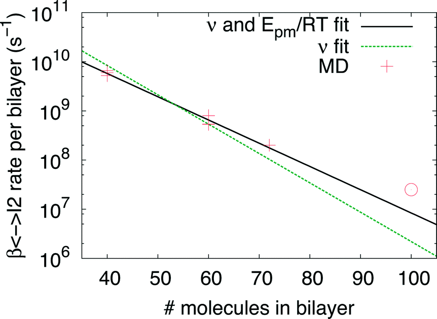 | ||
| Fig. 5 β↔ I2 shifting rate obtained from MD simulations14 with different simulation cell sizes as a function of number of molecules in a bilayer. The solid and dashed lines are results of fits of eqn (2) to the data crosses (see text for details). The circle is based on a single transition. | ||
The solid line in Fig. 5 shows the result of a fit of eqn (2) to the data points (crosses) using both the slope and intercept as free parameters. The circle, not included in the fit, shows an acceptable agreement with the fitted line. Here the prefactor is found to be ν = 4.5 × 10¹¹ s−1 in accordance with the expected range and the slope is −0.11, in very close agreement with the NEB results. The NEB results give a higher value since these are obtained with constant volume. In the molecular dynamics simulations, one of the cell angles changes during the transition, which should be the energetically favorable path. This is in accordance with experimental thermal stage microscopic observation where in some cases the crystal is found to “wobble” during the transition, but the cell parameters before and after the transition are again the same.14,21 The dashed line in Fig. 5 shows the fit with only the prefactor as a free parameter and  . In this case the prefactor results in ν = 2.1 × 10¹² s−1.
The obtained expression of the shifting rate allows us to make an estimation of time scales involved, a system with 300 molecules will slide roughly every 5 minutes from β to I2 or back. For a system of 620 molecules, a single shift takes already longer than the lifetime of the Universe. Since the barrier for the full transition to α is higher than for β ↔ I2, the scaling is even more dramatic. Clearly, the possibility of a cooperative motion has to break down at some point. Considering a transition temperature of roughly 350 K and the obtained barrier from the NEB calculations, for the rate limiting β → I1 transition, a system of 180 molecules transforms in roughly 3 minutes. This is smaller than the largest system studied here using NEB calculations which has 240 molecules in a single interface.
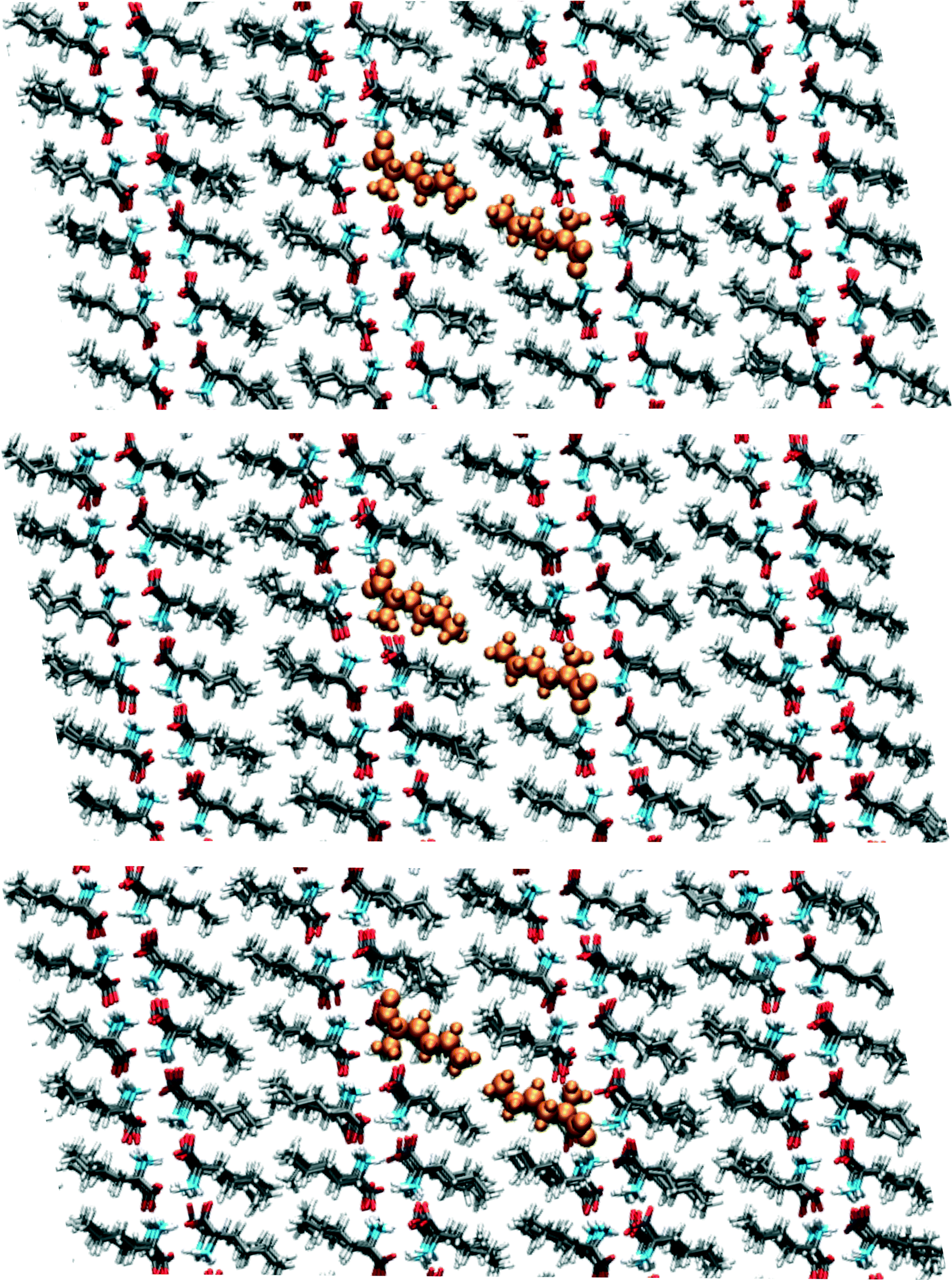
At this point, we return to the deviations from the linear scaling and show several snapshots along the transition path β to I1 – the rate limiting route – for the largest simulation cell. These are shown in Fig. 6 and include the initial β form, two intermediate images and the coordinates belonging to the transition state. Focusing on the hydrogen-bonded part of the bilayer, full cooperative motion can be observed, since this part moves gradually and concerted from β to the transition state. This movement further continues after the transition state. An xyz-file of the full trajectory is supplied as ESI.† The aliphatic tails of the norleucine molecules show, however, some deviations from the concerted motion. In the first image along the path, a modulation in the orientation of the tails can be observed: the aliphatic tails show more disorder. The length scale of this modulation is smaller than the simulation cell and hence not a direct consequence of the periodic boundary conditions. In the next image, a widening of the space between the bilayers can be observed, despite the simulation cell being constant in volume. The modulation also appears to have changed. The final image shows the transition state. In the following NEB images, which are not shown here, the motion of the bilayer continues while the disorder in the aliphatic chains gradually decreases and also the gap between the layers decreases. From these images we can draw three conclusions: (1) the transition also involves movement in the c direction, (2) the transition is cooperative for the hydrogen-bonded part of the bilayers, and (3) modulations in the aliphatic chains play a role. The cooperative aspect of the mechanism leads to linear scaling of the energy barriers with system size. However, the role of the observed modulations becomes increasingly important with system size, since longer wavelength modulations will become available. This will result in a lowering of the barrier. We would like to emphasize that these conclusions do not include any temperature effect and are purely based on the potential energy surface. We expect that the modulations will become increasingly important for higher temperatures, since more phonon modes will be excited.
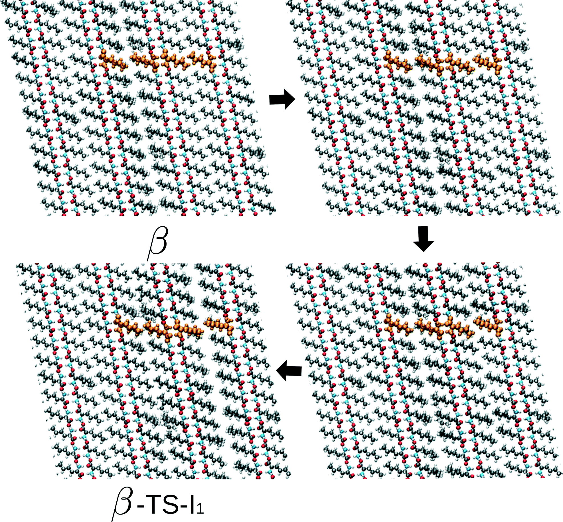 | ||
| Fig. 6 Series of images from β to the transition state on the way towards I1 (β-TS-I1). The four uniformly coloured orange molecules are a guide to the eye. | ||
3.2 Steered MD
To treat the effect of temperature and allow the simulation cell to change during the polymorphic transition, we use steered molecular dynamics (MD) simulations.22 This is a technique in which a moving harmonic restraint is added to the potential of an MD simulation and this restraint forces the system to follow a process of interest, which is in this paper the β → α solid–solid polymorphic transition. The process takes place at a finite temperature and because of the restraint, proceeds within a limited amount of computational time. In contrast to NEB calculations, obtaining information about the barrier using this technique is not straightforward, however, it will allow us to test whether our conclusions based on the potential energy surface still hold at elevated temperatures where fluctuations become increasingly important and might change the relative importance of the different routes in Fig. 2.We will steer the transition from β to α in one direction, either along a or b, and record the effect on the transition along the perpendicular direction. On the basis of the NEB results we expect steering in the a direction to result in a full transition, since it takes the system over the rate limiting barrier. Steering along b, on the other hand, is not expected to lead to a full transition. The effect of slow and fast steering is considered, and steering of one interface or two interfaces simultaneously, leading to eight different settings. Table 3 shows the results of 160 steered MD simulations, 20 for each setting. The results confirm the picture from the NEB results. Steering in the a direction leads to multiple shifts along b. Contrarily, shifting in b, does not result in extra shifts in the a direction. Only one of the 20 short simulations in which two interface were shifted along a simultaneously, resulted in a full transition of both steered interfaces. However, all simulations resulted in a full transition in one of the two affected interfaces. For several simulations, also transitions in other interfaces occurred. This is not surprising since shifts along b were found to occur during unbiased simulations at this temperature as well.
| Sim. time | 1 pair | 2 pair | ||
|---|---|---|---|---|
| a | b | a | b | |
| a The values in parentheses refer to the percentage of simulations in which a full transition occurred in one of the two affected interfaces. | ||||
| 50–5–50 ps | 95% | 0% | 5% (100%) | 0% |
| 100–10–100 ps | 100% | 0% | 45% (100%) | 0% |
We have visually inspected the trajectories of the steered MD simulations to study the mechanism of the partial phase transitions. In all 8 × 20 = 160 cases, the transition occurred in a cooperative way, which was not forced a priori since the steering at 2(4) pairs of atomic distances within a single(double) molecular pair could have induced phase transitions in different ways. Here, we will show a typical case and zoom in on the transition mechanism. To probe the movement of bilayers with respect to each other, 1D distances between molecules of the same chirality can be determined. Fig. 7 shows the time evolution of such 1D distances for one particular interface from one simulation of the (1 pair – a – 100–10–100)-category, see Table 3. The steered MD simulations force the a distance of one particular pair of molecules to gradually change in time. Fig. 7 shows that the average of this 1D distance over the full layer changes abruptly around 45 ps. At the same time, the distance between the layers, indicated by the 1D distance in c, increases lightly. Along the b direction, not much movement can be observed. Fig. 8 shows snapshots of this process, corresponding to the three solid symbols in the top panel of Fig. 7. The movement along a is not the full a/2. In the top snapshot, the closest contact (in this projection) between a Cε in one bilayer is the Cδ of a molecule in the opposing layer. For the bottom snapshot, it is a Cε of the same molecule, even after the shift. This change in local environment is accommodated by a change in the c distance. Fig. 7 shows that this c distance remains after the transition.
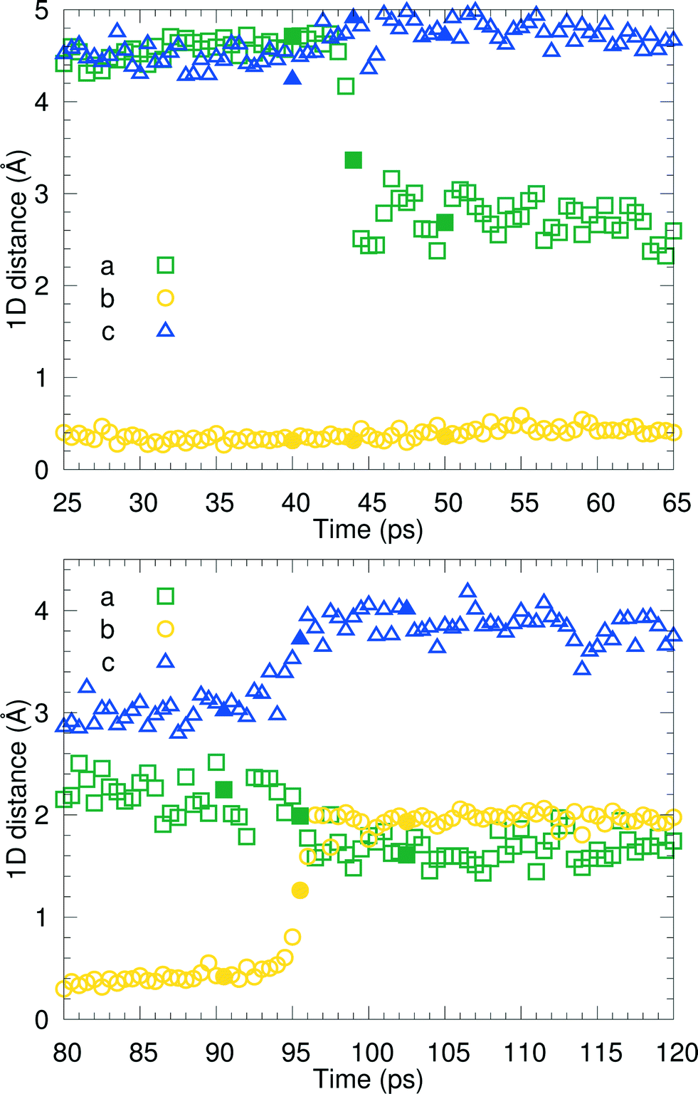 | ||
| Fig. 7 Time evolution of the 1D distance parameters within a typical steered MD run in the vicinity of the two transitions, β → I1 around 45 ps in the top panel and I1 → α around 95 ps in the bottom panel. | ||
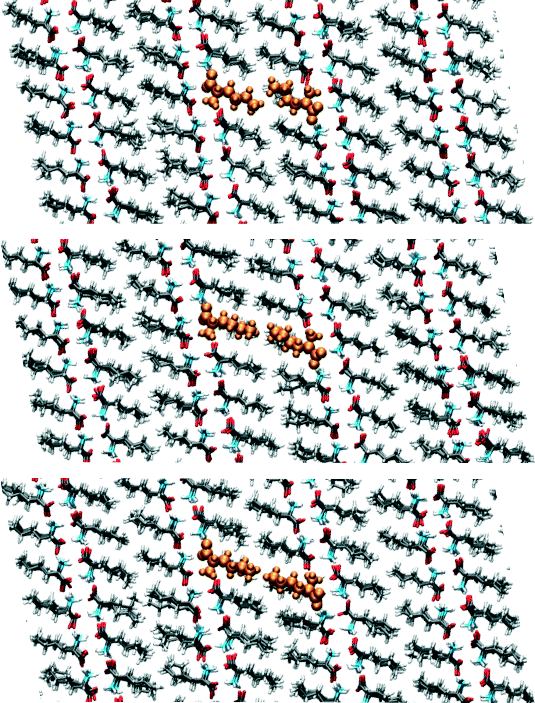 | ||
| Fig. 8 Snapshots corresponding to the filled symbols in the top panel of Fig. 7, the top panel is at 40, the middle at 44 and the bottom at 50 ps. The uniformly coloured molecules in orange are a guide to the eye. The plane shown is the ac-plane. | ||
Around 95 ps, a spontaneous transition in the b direction occurs, which completes the full transition towards α. Again this is a well-defined transition and snapshots during the transition indicate that it is cooperative. A substantial distance change in c can be observed as well as a small change in a, adding up to a full shift over a/2. This small change in a is visualized in Fig. 9 in which snapshots in the ac-plane are shown. Close inspection of the trajectory indicates that these changes in a, do not change the relative orientation of the layers in the a direction. The increase in 1D distance parameter corresponding to c is caused by the changes in the simulation cell which change the direction of the lattice vector c and therefore influences the projection along this vector. Apparently, this only occurs for the I1 → α and not for the β → I1 transition.
 | ||
| Fig. 9 Snapshots corresponding to the filled symbols in the bottom panel of Fig. 7, the top panel is at 90.5, the middle at 95.5 and the bottom at 102.5 ps. The uniformly coloured molecules in orange are a guide to the eye. The plane shown is the ac-plane. | ||
In principle, it is possible to use steered MD to determine the free energy profile of a process through the usage of the Jarzynski equation,23 〈exp(−βW)〉 = exp(−βΔF), in which 〈〉 means averaging over an ensemble of different realizations, β = 1/(kBT) and W is the work performed by the spring. However, to fully exploit this equation, (i) a good estimate of the average is required and (ii) one needs to use a stiff spring constant,24 which implies a close following by the spring of the steered variable. We have chosen not to use the Jarzynski equation for two reasons: requirement (i) is computationally expensive because it requires many different realizations, but more importantly requirement (ii) limits the choice of the steering variable to including more pairs and it could therefore force the transition to become cooperative. This would make it impossible to study the transition mechanism itself.
4 Discussion & conclusions
Both in the NEB and in the steered MD calculations, the most likely route to go from the β polymorphic form to the α polymorph is by first shifting along a and then over b. We have characterized the intermediate state and found that that first movement mainly involves shifting over a, but requires some widening of the layers as well. In the second step, the layers also move in the a and c direction.Linear and isotropic scaling of the energy barriers with simulation cell size is a clear indication for a cooperative mechanism, instead of through a nucleation and growth mechanism or a 1D or 2D “zipper”-like mechanism. We have observed this linear scaling to a large extent and indeed found the transition rate to scale exponentially with the number of molecules involved in the cooperative motion. The consequence of this is that a size limit for a fully concerted mechanism is easily reached and for this particular system, we estimate it to be around 180 molecules, which is roughly 10 × 10 molecules in one side of the interface and 10 × 10 molecules in the other side. This small number might explain why experimentally part of the crystal is found not to transform over the course of several hours.21 For these cases, the onset of a possible transition might require more than 180 molecules to move concertedly. One could imagine that the amount of molecules required is dictated by the local defect density. The NEB calculations show that modulations in the conformations of the aliphatic tails can substantially lower the transition energy barrier, stretching the 180 molecule limit. Although we expect these modulations to be more important at higher temperatures since phonon modes are more populated, we could not confirm this hypothesis using the steered molecular dynamics simulations for two main reasons. Since the simulations are performed at a temperature of 350 K, the aliphatic tails exert some thermal motion and it is hence hard to discern the role of additional fluctuations in the transition from snapshots of the trajectory. The second reason is the relatively small system size. The influence of the modulations only became apparent in the NEB calculations of the largest system size. The statistical study we aimed at for this paper, is too computationally demanding to perform on these simulation cell sizes. We believe, however, that the conclusions from the steered MD remain intact even for this larger cell sizes: the transition occurs through I1 and also its characterization will not change. In a future study we aim to focus more on the possible role of these fluctuations in polymorphic transitions in general.
To keep large simulation cells computationally affordable, coarse-grained models are often applied. These are models in which not all atoms are simulated but a more approximate description of the system is used. Our results show the risk of such an approach since local conformational disorder cannot be picked up, but this disorder might be the reason why cooperative mechanisms are still sustainable at longer length scales. Long biased simulations with large simulation cells could settle this issue. Another possible outcome could be a mechanism where the formation of a nucleus of the new phase through cooperative motion, which then grows through propagation in a wave-like manner through the crystal. At the length scale of the initial size of the cluster, classical nucleation theory and the cooperative mechanism could naturally come together. In this process defects might hamper the propagation.
To conclude, we like to reiterate the danger of extracting information about transition mechanisms on the basis of structural information of the initial and final phases. In this way, intermediate forms will be neglected, with an incomplete picture of the solid–solid polymorphic transition as a result. Moreover, energy barrier issues can be easily overlooked.
5 Simulation methods
The force field, AMBER,25 and specific settings chosen to study the β → α solid–solid polymorphic transition of DL-norleucine are the same as in ref. 14 and 15.5.1 Nudged elastic band calculations
In our earlier work considering partial phase transitions in the bc-plane, we showed that a transition in which one interface is affected results in a change in the shape of the simulation cell (Fig. 6 of ref. 13), while during a transition in which two interfaces are affected the shape of the cell only temporarily changes (Fig. 5 of ref. 13). This has implications for the modelling, since the used implementation of NEB only allows for calculations at constant volume and shape of the simulation cell. We have therefore chosen to perform the NEB calculations on a shift of one full bilayer affecting two interfaces, see the black arrow in Fig. 3.All NEB calculations are done with LAMMPS.26 For all sizes two pairs of molecules are selected. Both pairs are situated within a neighbouring interface of bilayers. Within these four molecules, three atoms (Cα, Cδ, and Cε) are used for the springs with a force constant of 25 kJ mol−1 Å−2 between the 14 NEB images spanning the transition path between the stable β and α structures, see also Fig. 3. From the initial image, the end images are constructed by a shift of one bilayer over b/2, a/2 or b/2 + a/2, which affects two interfaces of bilayers. The 12 images in between are constructed as a linear interpolation and are provided as input for the calculations. All 14 images are optimized before starting the NEB-calculations, except for the 3 × 5 × 2 case. Convergence criteria are based on the global force vector and are therefore different per size: 3 × 5 × 2: 0.8 kJ mol−1 Å−1, 6 × 5 × 2: 2.3 kJ mol−1 Å−1, 3 × 10 × 2: 2.3 kJ mol−1 Å−1, and 6 × 10 × 2: 4.5 kJ mol−1 Å−1. The timestep for the ‘quickmin’ damped dynamics minimizer27 is 0.5 fs. A climbing image28 stage of the calculation has not been performed. However, since the objective is to study trends as a function of simulation cell size, we do not expect this to severely influence our conclusions.
Effectively, the studied sizes correspond to replicas of the starting coordinates in the multiples: 2 × 1 × 1, 1 × 2 × 1, and 2 × 2 × 1.
5.2 Steered molecular dynamics simulations
All steered MD22 calculations are done with LAMMPS26 after it has been interfaced with PLUMED.29 Similar to the NEB calculations, the moving restraint is applied to the Cα, Cδ, and Cε atoms of pairs of molecules of which both members of the pair belong to the same interface of bilayers. However, in the case of steered MD there are two pronounced differences with respect to the NEB. Instead of shifting over b/2 or a/2, the Cartesian y and z-components of the distances within the pairs are used as a probe for the crystallographic b and a-direction. Steering occurs over 2.5 Å for the y-distance and over 5.0 Å for the z direction, which are approximations of b/2 and a/2. When steering over z, the distances taken into account are Cα–Cα and Cδ–Cδ, when steering over y the restraint works on Cα–Cα and Cε–Cε distances. Another pronounced difference is the study of both single affected interfaces, which is achieved by steering on one pair of molecules, and double affected interfaces, which is achieved by steering on two pairs of molecules. This gives a total of four different set-ups for the steered MD, all beginning with the starting coordinates as shown in Fig. 3. Moreover, we use two lengths of time to steer: 50 ps with 5 ps afterwards for a linear decrease of the spring constant at the same position of the spring followed by 50 ps without any spring influence and the same procedure with 100 ps, 10 ps and 100 ps, respectively. Springs corresponding to Cartesian components of the Cα–Cα distance have a force constant of 250 kJ mol−1 Å−2 and springs corresponding to either Cδ–Cδ or Cε–Cε have a force constant of 100 kJ mol−1 Å−2. Stiffer springs resulted in decomposition of the hydrogen-bonded bilayers, since only one pair of molecules is steered per interface.The temperature is 350 K in all cases, which is a temperature where the β polymorphic form is metastable and the α polymorphic form is stable. To describe the thermal fluctuations for each setting, 20 different trajectories are generated through usage of different starting velocities. The simulations are performed in the NPT ensemble30 at atmospheric pressure and with a characteristic time scale for the barostat of 400 fs and for the thermostat of 40 fs. The timestep of integration is 0.5 fs. All figures of the steered MD snapshots and NEB images have been made with VMD.31
Acknowledgements
This research was financially supported by the VIDI Research Program 700.10.427, which is financed by The Netherlands Organisation for Scientific Research (NWO), and the European Research Council (ERC-2010-StG, Grant Agreement No. 259510-KISMOL). We thank the anonymous referees for their extensive comments, which have helped us in restructuring the paper. Finally, we thank Dr. Hugo Meekes for critically reading the manuscript.References
- J. Bernstein, Polymorphism in Molecular Crystals, Oxford Science Publications, Great Clarendon Street Oxford OX2 6DP, 2002 Search PubMed.
- S. Mondal and G. Mugesh, Angew. Chem., Int. Ed., 2015, 54, 10833–10837 CrossRef CAS PubMed.
- J. D. Dunitz and J. Bernstein, Acc. Chem. Res., 1995, 28, 193–200 CrossRef CAS.
- D.-K. Bučar, R. W. Lancaster and J. Bernstein, Angew. Chem., Int. Ed., 2015, 54, 6972–6993 CrossRef PubMed.
- J. D. Dunitz, Pure Appl. Chem., 1991, 63, 177–185 CrossRef CAS.
- P. Naumov, S. Chizhik, M. K. Panda, N. K. Nath and E. Boldyreva, Chem. Rev., 2015, 115, 12440–12490 CrossRef CAS PubMed.
- F. H. Herbstein, Acta Crystallogr., Sect. B: Struct. Sci., 2006, 62, 341–383 Search PubMed.
- Y. Mnyukh, N. Panfilova, N. Petropavlov and N. Uchvatova, J. Phys. Chem. Solids, 1975, 36, 127–144 CrossRef CAS.
- S. C. Sahoo, S. B. Sinha, M. S. R. N. Kiran, U. Ramamurty, A. F. Dericioglu, C. M. Reddy and P. Naumov, J. Am. Chem. Soc., 2013, 135, 13843 CrossRef CAS PubMed.
- A. M. Mathieson, Acta Crystallogr., 1953, 6, 399–403 CrossRef CAS.
- M. M. Harding, B. M. Kariuki, L. Williams and J. Anwar, Acta Crystallogr., Sect. B: Struct. Sci., 1995, 51, 1059–1062 CrossRef.
- B. Dalhus and C. H. Görbitz, Acta Crystallogr., Sect. C: Cryst. Struct. Commun., 1996, 52, 1761–1764 CrossRef.
- J. A. van den Ende and H. M. Cuppen, Cryst. Growth Des., 2014, 14, 3343–3351 CAS.
- J. A. van den Ende, M. M. H. Smets, D. T. de Jong, S. J. T. Brugman, B. Ensing, P. T. Tinnemans, H. Meekes and H. M. Cuppen, Faraday Discuss., 2015, 179, 421–436 RSC.
- U. Mukhopadhyay and I. Bernal, Mendeleev Commun., 2004, 14, 270–276 CrossRef.
- G. Henkelman and H. Jónsson, J. Chem. Phys., 2000, 113, 9978–9985 CrossRef CAS.
- S. C. Tuble, J. Anwar and J. D. Gale, J. Am. Chem. Soc., 2004, 126, 396–405 CrossRef CAS PubMed.
- J. Anwar, S. C. Tuble and J. Kendrick, J. Am. Chem. Soc., 2007, 129, 2542–2547 CrossRef CAS PubMed.
- D. Zahn and J. Anwar, Chem. – Eur. J., 2011, 17, 11186–11192 CrossRef CAS PubMed.
- D. Zahn and J. Anwar, RSC Adv., 2013, 3, 12810–12815 RSC.
- M. M. H. Smets, S. J. T. Brugman, E. R. H. van Eck, J. A. van den Ende, H. Meekes and H. Cuppen, Cryst. Growth Des., 2015, 15, 5157–5167 CAS.
- H. Grubmüller, B. Heymann and P. Tavan, Science, 1996, 271, 997–999 Search PubMed.
- C. Jarzynski, Phys. Rev. Lett., 1997, 78, 2690–2693 CrossRef CAS.
- S. Park and K. Schulten, J. Chem. Phys, 2004, 120, 5946–5961 CrossRef CAS PubMed.
- W. D. Cornell, P. Cieplak, C. I. Bayly, I. R. Gould, K. M. Merz, D. M. Ferguson, D. C. Spellmeyer, T. Fox, J. W. Caldwell and P. A. Kollman, J. Am. Chem. Soc., 1995, 117, 5179–5197 CrossRef CAS.
- S. Plimpton, J. Comput. Phys., 1995, 117, 1–19 CrossRef CAS.
- D. Sheppard, R. Terrell and G. Henkelman, J. Chem. Phys, 2008, 128 Search PubMed.
- G. Henkelman, B. P. Uberuaga and H. Jónsson, J. Chem. Phys, 2000, 113, 9901–9904 CrossRef CAS.
- G. A. Tribello, M. Bonomi, D. Branduardi, C. Camilloni and G. Bussi, Comput. Phys. Commun., 2014, 185, 604–613 CrossRef CAS.
- M. Parrinello and A. Rahman, J. Appl. Phys., 1981, 52, 7182–7190 CrossRef CAS.
- W. Humphrey, A. Dalke and K. Schulten, J. Mol. Graphics, 1996, 14, 33–38 CrossRef CAS PubMed.
Footnote |
| † Electronic supplementary information (ESI) available: xyz-trajectory of the converged NEB-band for the rate limiting step (β → I1) within the 6 × 10 × 2 system. See DOI: 10.1039/c5ce02550h |
| This journal is © The Royal Society of Chemistry 2016 |