 Open Access Article
Creative Commons Attribution 3.0 Unported Licence
Spontaneous reaction between an uncharged lithium iron silicate cathode and a LiPF6-based electrolyte
Zachary
Arthur
a,
Hsien-Chieh
Chiu
b,
Xia
Lu
 b,
Ning
Chen
c,
Vincent
Emond
a,
Karim
Zaghib
d,
De-Tong
Jiang
*a and
George P.
Demopoulos
*b
aDepartment of Physics, University of Guelph, 50 Stone Road East, Guelph, ON N1G 2W1, Canada. E-mail: djiang@uoguelph.ca
bMaterials Engineering, McGill University, Montreal, QC H3A 0C5, Canada. E-mail: george.demopoulos@mcgill.ca
cCanadian Light Source, 44 Innovation Boulevard, Saskatoon, SK S7N 2V3, Canada
dInstitut de Recherche d’Hydro-Québec (IREQ), Varennes, QC J3X 1S1, Canada
First published on 22nd October 2015
Abstract
The reaction between an uncharged Li2FeSiO4 (LFS) cathode and a LiPF6-EC/DMC electrolyte is revealed by in situ XANES in coin cells. This study shows clear evidence of delithiation and iron oxidation in LFS prior to cycling. Subsequent cycling appears to partially restore the original lithiation level, an observation that needs to be taken into consideration in future LFS development work.
Today, lithium-ion batteries (LIBs) are ubiquitous; they can be found everywhere from our portable electronics, to the automotive and renewable energy sector.1,2 Indeed, LIBs have been a crucial enabling component in the development of many of the transformative technologies we have seen emerging since the early 2000s, e.g. smart phones, electric cars, etc. In order to improve the current generation of LIBs it is necessary to develop low cost, safe, and high energy density cathode materials. One material class that has been garnering great interest in this respect is that of Li2MSiO4 (LMS, M = Fe, Mn) silicates, an olivine structure that has a theoretical charge capacity of 330 mA h g−1,3,4 double of that of lithium iron phosphate5.
The challenges currently facing the development of LFS (M = Fe) cathodes are not trivial. The charge compensation mechanism for Li1−xFeSiO4, 0 < x < 1, is still not fully understood,6,7 and the extraction of more than one lithium results in capacity loss, attributed to Fe–Li anti-site defects and phase transitions induced during charging–discharging.6,8 Meanwhile, the compatibility between the electrolyte and the cathode may be a cause of concern as well,9,10 especially in this case because the fluorine in the typical, most popular LiPF6-based electrolyte could react with the Si species in LFS.11–13 However, the preceding studies have either looked into the LFS–electrolyte interaction issue by post mortem (i.e. after cycling) ex situ surface characterization using techniques like XPS12 or by bulk characterization using XRD and EDX following aggressive ageing at 60 °C.11 Understanding the electrode–electrolyte interphasial phenomena as proven in the case of the well-known solid-electrolyte interphase (SEI)9,14 is crucial for the development of robust silicate cathode Li-ion batteries. In particular in situ probing of these phenomena can provide critical missing links in this regard.
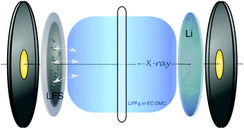
In this study, the spontaneous reaction between an uncharged (prior to cycling) Li2FeSiO4 (LFS) cathode and a LiPF6-EC/DMC electrolyte is studied by in situ X-ray absorption near-edge spectroscopy (XANES) using coin cells. The LFS cathode (80% LFS, 10% acetylene black and 10% PVDF) featured Li2FeSiO4 nanoparticles prepared via an organic-assisted hydrothermal-annealing (180 °C and 400 °C, respectively) synthesis method.15 The cathode slurry was rolled onto an Al foil current collector, and assembled into a modified CR2032 coin cell with a Li anode, a 25 μm PP/PE/PP separator (Celgard 2325), and using 1 M of LiPF6 in EC/DMC (1![[thin space (1/6-em)]](https://www.rsc.org/images/entities/char_2009.gif) :
:![[thin space (1/6-em)]](https://www.rsc.org/images/entities/char_2009.gif) 1 by volume) as the electrolyte. A schematic view of this setup can be seen in Fig. 1.
1 by volume) as the electrolyte. A schematic view of this setup can be seen in Fig. 1.
 | ||
| Fig. 1 Schematic of the in situ CR2032 coin cell with Kapton® windows used for XANES monitoring of the LFS–electrolyte interaction (depicted with arrows at the solid–electrolyte interphase). | ||
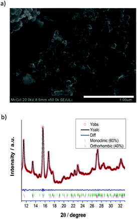
The pristine LFS sample was characterized using SEM, XANES, and synchrotron radiation XRD. From SEM imaging and processing using Image J16 (Fig. 2a), the particle area was determined to be on average 1270 ± 285 nm2. This reveals that the pristine material is composed of nanoparticles on the order of ∼40 nm and is in the form of aggregates.15 Synchrotron-radiation XRD and XANES measurements were taken at the HXMA beamline at the Canadian Light Source (CLS).17 The CLS HXMA wiggler was running at 1.9 T and the CLS storage ring was with a 250 mA current. The Si(111) monochromator crystals in combination with an Rh coated pre-mono collimating mirror and a post-mono toroidal focusing mirror were used. For the XANES measurements, both the incoming and transmitted X-ray intensity were monitored using ionization chambers filled with He gas, the fluorescence yield was monitored using a Lytle detector filled with N2 gas, and data were reduced using Athena;18 for XRD detection a mar345 image plate was used to record the Debye–Scherrer rings from a modified CR2032 cell (Fig. 1), and rings were integrated using fit2D.19 XANES was performed at the Fe K-edge and the XRD patterns were recorded at 17 keV photon energy; energy calibration was performed by determining the first inflection point of standard Fe and Yt XANES, for the respective energies. The mar345 detector distance was calibrated using a NIST LaB6 powder mounted inside an in situ cell case, and fit2D's calibration function. The as-prepared material was found to be a mixture of approximately 3![[thin space (1/6-em)]](https://www.rsc.org/images/entities/char_2009.gif) :
:![[thin space (1/6-em)]](https://www.rsc.org/images/entities/char_2009.gif) 2 of monoclinic P21/n (γs) and the “low temperature” orthorhombic Pmn21 (βII) phases (Fig. 2b), respectively.20
2 of monoclinic P21/n (γs) and the “low temperature” orthorhombic Pmn21 (βII) phases (Fig. 2b), respectively.20
In situ XANES measurements of the cathode were performed on the initial uncharged battery state (96 hours following the coin cell assembly during which LFS was in contact with 1 M of LiPF6 in EC/DMC solvent) as well as after cycling the cell at the C/20 rate for a single Li extraction–insertion (formation) cycle. The “uncharged” cell is labelled 20C0 and the “cycled” cell, 20Df. These three samples correspond to the same electrochemical state, and represent the typical spectra we have measured for this material in these electrochemical states.
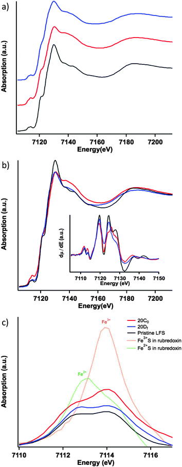
The normalized Fe K-edge XANES spectra in Fig. 3a show the results for the different LFS samples. The differences among the electronic structures of the three LFS samples are subtle but nevertheless noticeable. The first of which is that, the pristine sample (Fig. 3a and b black) shows well-resolved spectral features following the “white-line” area (i.e. the strongest peak area above the edge jump), compared to the other two samples: 20C0 and 20Df, uncharged and cycled (formation cycle), respectively. This reflects the increase of structural disorder in samples 20C0 and 20DF.† For sample 20C0 this means that the contact of the LFS cathode with the electrolyte inside the coin cell (96 hours of storage time at room temperature) has triggered a spontaneous reaction resulting in a noticeable structural change in the cathode material. Upon cycling (formation cycle) however, the cathode (20Df sample) is seen to restore, in part, its local structure towards that of the pristine sample. This can be seen by comparing the post-white-line” region (Fig. 3b) and more clearly in the derivative spectra. The first derivatives of the XANES spectra for the three samples are shown in the insetof Fig. 3b, and were calculated using the central difference method. Here the restoration trend can be seen by following the peak at around 7125 eV. This corresponds to the inflection point just before the “white-line” region (where the spectra are free of any pre-edge effects caused by Jahn–Teller distortions). Specifically this derivative peak moves toward higher energy in the uncharged material and then returns to the same position as the pristine upon cycling.
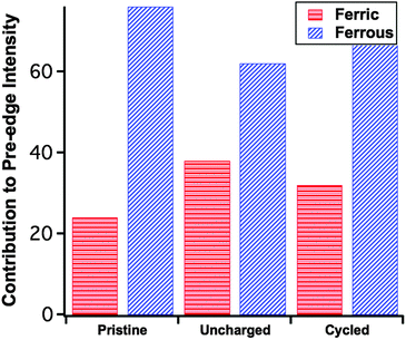
The previous observations are echoed by the trend of the pre-edge features (Fig. 3c), that is the pristine sample has the lowest overall pre-edge intensity while the uncharged has the highest. This feature is reflective of the distortion of the FeO4 tetrahedron via the Jahn–Teller effect.21 Here the cycled cathode pre-edge intensity is between that of the other two, indicating again a certain level of structural restoration. In addition to the overall pre-edge intensity differences, Fig. 3c shows clearly the varying intensity distribution profiles among the three, which are related to the underlying spectral components of different oxidation species.22 To facilitate further analysis, in Fig. 3c two low-temperature reference phases have been included for the ferrous and ferric states of Fe. These are the tetrahedrally coordinated Fe2+S4 and Fe3+S4 found in rubredoxin.23 The ratio of the pre-edge features contributed by the ferrous and ferric states was fit using a linear combination18 of pre-edges from the Fe2+S4 and Fe3+S4 reference data. The fitting results are summarized in Fig. 4, each fit performed reported an R-factor18 less than 0.025. The results show that the Fe site within the LFS matrix indeed became oxidized (likely with the reduction of the electrolyte) during the 96 hour interphasial interaction; upon cycling, this state was partially restored towards the original ferrous/ferric ratio in the pristine sample.
The relative spectral intensity increase of Fe3+ in the uncharged cathode compared to pristine (Fig. 4) is usually a direct fingerprint of the charge compensation process throughout a normal charging sequence. Here however, no external charging has been applied. In this case, in the absence of any applied current, this pre-edge profile variance indicates the delithiation of the material as a consequence of reduction of an electrolytic component. Previous research by Dippel et al.13 involving the ageing of the LFS material in a hot (60 °C) LiPF6-EC/DMC organic electrolyte concluded that LFS converts under those conditions into Li2SiF6 with simultaneous dissolution of iron into the electrolyte. No delithiation or iron oxidation was reported as observed here. The same group in a follow up study11 commented that the electrolyte was thermally decomposed at 60 °C even in the absence of LFS hence the previous high temperature study appears to have observed reactions not necessarily operational in an actual coin cell that is typically used at lower temperatures. As per other electrode–electrolyte interphase systems14 it is likely that the reduction of the organic carbonate solvent molecules takes place on the surface of LFS leading to iron oxidation.
As a plausible mechanism for the observed spontaneous reaction between the LiPF6-EC/DMC electrolyte and Li2FeSiO4 (LFS) we propose tentatively the following sequence. Fluoride anions (released from LiPF6) owing to their well-known propensity to form Si–F groups (such as SiF6−) are envisaged to react with the surface of LFS as noted in Ensling et al.'s XPS analysis.12 Such Si–F interaction on the LFS surface would weaken the FeII–SiO4 bonding making iron(II) prone to oxidation via reduction of electrolyte components such as EC and DMC that is well established in the literature.13 In other words the oxidation of Fe(II) in this case is rendered feasible because of the F-induced weakening of the FeII–Si–Ox bonding caused by the Si–F interaction. Further detailed investigations would be needed to allow for a deeper understanding of this reaction and we are in the process of doing that.
Beyond the observation of the spontaneous reaction (while the cell is uncharged) another important revelation of this work is the finding that after the first charge–discharge cycle there is (at least in part) restoration of the LFS structure as evident by the oxidation state of iron. Thus the relative spectral intensity of Fe3+ was reduced from ∼37% at the “uncharged” state (i.e. following the spontaneous reaction) to approximately 32% at the discharged state (after the formation cycle) compared to 24% for the particular pristine sample used in this work (Fig. 4). It should be pointed out that the cycling process is known to produce a crystalline phase change in the pristine material,8,15 which could affect the overall intensity of the pre-edge features. The above analysis is concerned only with the relative ratio of Fe2+ and Fe3+ contributions to the overall pre-edge spectrum. What these results imply in terms of battery performance, however, is that though the reduction of the electrolyte does occur spontaneously and slightly increases the state-of-charge (SOC) of LFS during coin cell pre-cycling storage, the accompanying delithiation reaction is at least in part reversible. Given these findings further research is warranted not only in elucidating this complex interphasial reaction but also in assessing its role in the overall structural stability and loss of irreversibility during cycling of this important cathode material. The study of an alternative to F-containing electrolytes is equally important in this context.
In summary, in situ Fe K-edge XANES reveals a spontaneous interphasial reaction between the uncharged Li2FeSO4 cathode and the LiPF6-based electrolyte, manifested with the Fe2+/Fe3+ ratio variation from the pristine state. Subsequent cycling of the cathode material (formation cycle) is partially restorative in the Fe oxidation state.
The authors acknowledge assistance provided during data acquisition by Dr W. Chen and Dr C.-Y. Kim. Further acknowledgement and gratitude are extended to Dr L. Zhang (University of Nebraska-Lincoln) for providing the reference compound data. This work is supported through a Hydro-Québec/Natural Sciences & Engineering Research Council of Canada (NSERC) Collaborative R&D research grant. DTJ acknowledges Canadian NSERC support for the work done at the University of Guelph. Synchrotron radiation measurements were performed at the CLS, which is supported by CFI, NSERC of Canada, University of Saskatchewan, Government of Saskatchewan, Western Economic Diversification Canada, NRC Canada, and CIHR.
Notes and references
- J. M. Tarascon and M. Armand, Nature, 2001, 414, 359–367 CrossRef CAS PubMed.
- J. B. Goodenough and K.-S. Park, J. Am. Chem. Soc., 2013, 135, 1167–1176 CrossRef CAS PubMed.
- M. E. Arroyo-de Dompablo, M. Armand, J. M. Tarascon and U. Amador, Electrochem. Commun., 2006, 8, 1292–1298 CrossRef CAS.
- A. Nytén, A. Abouimrane, M. Armand, T. Gustafsson and J. O. Thomas, Electrochem. Commun., 2005, 7, 156–160 CrossRef.
- M. S. Islam, R. Dominko, C. Masquelier, C. Sirisopanaporn, A. R. Armstrong and P. G. Bruce, J. Mater. Chem., 2011, 21, 9811–9818 RSC.
- D. Lv, J. Bai, P. Zhang, S. Wu, Y. Li, W. Wen, Z. Jiang, J. Mi, Z. Zhu and Y. Yang, Chem. Mater., 2013, 25, 2014–2020 CrossRef CAS.
- A. W. Brownrigg, G. Mountjoy, A. V. Chadwick, M. Alfredsson, W. Bras, J. Billaud, A. R. Armstrong, P. G. Bruce, R. Dominko and E. M. Kelder, J. Mater. Chem. A, 2015, 3, 7314–7322 CAS.
- A. R. Armstrong, N. Kuganathan, M. S. Islam and P. G. Bruce, J. Am. Chem. Soc., 2011, 133, 13031–13035 CrossRef CAS PubMed.
- J. B. Goodenough and Y. Kim, Chem. Mater., 2010, 22, 587–603 CrossRef CAS.
- Y. Li, M. Bettge, B. Polzin, Y. Zhu, M. Balasubramanian and D. P. Abraham, J. Electrochem. Soc., 2013, 160, A3006–A3019 CrossRef CAS.
- C. Dippel, S. Krueger, V. Kraft, S. Nowak, M. Winter and J. Li, Electrochim. Acta, 2013, 105, 542–546 CrossRef CAS.
- D. Ensling, M. Stjerndahl, A. Nyten, T. Gustafsson and J. O. Thomas, J. Mater. Chem., 2009, 19, 82–88 RSC.
- C. Dippel, S. Krueger, R. Kloepsch, P. Niehoff, B. Hoffmann, S. Nowak, S. Passerini, M. Winter and J. Li, Electrochim. Acta, 2012, 85, 66–71 CrossRef CAS.
- K. Xu, Chem. Rev., 2014, 114, 11503–11618 CrossRef CAS PubMed.
- X. Lu, H. Wei, H.-C. Chiu, R. Gauvin, P. Hovington, A. Guerfi, K. Zaghib and G. P. Demopoulos, Sci. Rep., 2015, 5, 8599 CrossRef CAS PubMed.
- C. A. Schneider, W. S. Rasband and K. W. Eliceiri, Nat. Methods, 2012, 9, 671–675 CrossRef CAS PubMed.
- D. T. Jiang, N. Chen and W. Sheng, AIP Conf. Proc., 2007, 879, 800–803 CrossRef CAS.
- B. Ravel and M. Newville, J. Synchrotron Radiat., 2005, 12, 537–541 CrossRef CAS PubMed.
- A. P. Hammersley, S. O. Svensson, M. Hanfland, A. N. Fitch and D. Hausermann, High Pressure Res., 1996, 14, 235–248 CrossRef.
- C. Eames, A. Armstrong, P. Bruce and M. Islam, Chem. Mater., 2012, 24, 2155–2161 CrossRef CAS.
- G. Frank de, V. György and G. Pieter, J. Phys.: Condens. Matter, 2009, 21, 104207 CrossRef PubMed.
- T. E. Westre, P. Kennepohl, J. G. DeWitt, B. Hedman, K. O. Hodgson and E. I. Solomon, J. Am. Chem. Soc., 1997, 119, 6297–6314 CrossRef CAS.
- L. Zhang, 2015, private communication.
Footnote |
| † Heterogeneity of unique local ionic environments offers on average a higher continuity of available states. In effect, XANES peak broadening can be due to the presence of multiple crystalline phases, or, as is the case here, from an increased local structure disorder within the same phase. |
| This journal is © The Royal Society of Chemistry 2016 |


