New anthracene-based organic dyes: the flexible position of the anthracene moiety bearing isolation groups in the conjugated bridge and the adjustable cell performance†
Huiyang
Li
a,
Manman
Fang
a,
Ting
Xu
a,
Yingqin
Hou
a,
Runli
Tang
a,
Junnian
Chen
a,
Linfeng
Liu
b,
Hongwei
Han
b,
Tianyou
Peng
a,
Qianqian
Li
*a and
Zhen
Li
*a
aDepartment of Chemistry, Hubei Key Lab on Organic and Polymeric Opto-Electronic Materials, Wuhan University, Wuhan 430072, China. E-mail: qianqian-alinda@163.com; lizhen@whu.edu.cn
bMichael Grätzel Center for Mesoscopic Solar Cells, Wuhan National Laboratory for Optoelectronics, Huazhong University of Science and Technology, Wuhan, 430072, China
First published on 7th December 2015
Abstract
Three organic sensitizers (LI-65–LI-67), featuring a 9,10-diarylsubstituted anthracene unit as part of the conjugated bridge, were designed and employed in dye-sensitized solar cells (DSCs). The two phenyl groups on the 9 and 10 positions of the anthracene ring acted as isolation groups, to suppress possible dye aggregation and electron recombination. With the flexible position of the isolation group in the conjugated bridge, interesting structure–property relationships were obtained: the isolation groups (the phenyl rings on the anthracene unit), close to the donor, were beneficial to the enhancement of the short circuit current (Jsc) values, with the highest Jsc value of 13.95 mA cm−2 (LI-65); once located in the middle of the π-bridge, the highest resistance of charge recombination and the longest electron lifetime were achieved and contributed to the enhanced open circuit voltage (Voc) of 722 mV, with the highest conversion efficiency (η) of 6.44% (LI-66, 25% higher than the lowest).
Introduction
As one of the most promising representatives of photovoltaic technology, dye-sensitized solar cells (DSCs) have been growing rapidly in the past two decades due to their advantages such as an environmentally friendly device fabrication process and excellent power conversion efficiencies.1 In DSCs, the sensitizer, which is anchored on the surface of the semiconductor (TiO2), fulfils the main role of capturing the solar energy and injection of the electrons.2 Many studies have shown that the structure of the sensitizers could exert a pivotal influence on the interfacial charge transfer and the charge recombination processes, playing a controlling role in determining the final conversion efficiency.3–8 Thus, interface engineering through tuning the structures of the sensitizers is undoubtedly an effective way towards DSCs with high performance. Up to now, through the ingenious design of metal-based sensitizers, power conversion efficiencies higher than 13% have been achieved by several research groups.9 Organic sensitizers were also investigated extensively by virtue of their relatively low cost, easier synthetic procedures and higher molar extinction coefficients. Some of them also showed distinguished efficiencies (>12%), ranking among the highest efficiency sensitizers.10–14Generally, most typical organic sensitizers consist of an electron donor (D), a π-conjugated bridge and an electron acceptor (A) with a binding group to anchor onto the surface of TiO2 (i.e., D–π-A structure). This D–π-A structure is beneficial to the intramolecular charge transfer (ICT), resulting in a high light-harvesting ability. However, in most rod-shaped sensitizers with D–π-A structures, I3− in the electrolyte can easily penetrate through the interspaces between sensitizers to approach the semiconductor surface, resulting in serious charge recombination. The planar configuration usually causes dye aggregation, which also increases charge recombination and the molecular interaction with adjacent sensitizers on the TiO2 surface.15 Thus, with the aim to avoid these unfavourable effects, many strategies have been utilized, such as the introduction of coadsorbents, twisting the dye structures, adding hydrophobic chains and rigid units as isolation groups, and so on.2,15–17 The incorporation of isolation groups has a remarkable impact on the suppression of dye aggregates, leading to the enhancement of overall conversion efficiencies. For example, Tian et al. designed and synthesized a novel type of starburst triarylamine based sensitizers by adding some rigid groups on the outside of the triarylamine (the donor part), which exhibited higher conversion efficiency than similar ones with triphenylamine as the electron donor (Fig. S1†).15,18,19 Hara et al. reported a series of organic dyes with alkyl-functionalized oligothiophenes as the conjugated bridges. These long alkyl chains can act as isolation groups to increase the Voc value and electron lifetime of the corresponding solar cell in a large degree (Fig. S2†).20
Considering the importance of isolation groups, our group has devoted some efforts to explore the relationship between the isolation group and the device performance. Firstly, we introduced one isolation group to the sensitizer, which was linked to the nitrogen atom of the pyrrole ring as a conjugated bridge.21 The isolation groups were interchangeable, both flexible chains and rigid rings could be employed.22 Moreover, the two pieces of sensitizer moieties were linked by one isolation group to form “H” type sensitizers, which exhibited better device performance (Fig. S3†).22,23 Then, the number of isolation groups increased from one to two.24 We incorporated two tetraphenylethylene (TPE) moieties, a typical molecule with the characteristic of aggregation induced emission (AIE), into the donor part of the sensitizers. The TPE units acted as protective umbrellas, which played an important role to suppress dye aggregation, but the photovoltaic performance still needed to be further improved (Fig. S4†). Thus, one of the two isolation groups was moved to the bridge part to realize a better isolation effect between the sensitizers (Fig. S4†).25 This strategy was also applied to anthracene-based sensitizers, in which both the donor and conjugated bridge carried isolation groups (Fig. 1 and S5†).26
The anthracene (An) fused ring system has been intensively studied and employed in light-emitting diodes, field effect transistors and polymer solar cells, due to its extensive planar conjugation system.27–31 However, its application in dye-sensitized solar cells has been relatively rare.26,32 Generally, the 2,6-substitution mode allows retention of the high planarity and extends the conjugation between the anthracene ring and its adjacent units; in 9,10-diarylsubstituted anthracenes, there are large torsions between the anthracene moiety and the aromatic rings in the 9 and 10 positions with dihedral angles as large as ∼80°.32–34 Thus, aromatic rings in the anthracene 9 and 10 positions can act as isolation groups to suppress molecular interaction and charge recombination. A series of anthracene-based sensitizers have therefore been synthesized in our group to improve the photovoltaic performance. Among them, LI-59 exhibited the highest conversion efficiency (Fig. 1), which further confirmed the isolation effect of the aromatic rings in the 9 and 10 positions of anthracene. As mentioned above, the number and position of the isolation groups in organic dyes have a large influence on the photovoltaic performance. Thus, we wondered what the most appropriate position might be for the isolation groups in the conjugated bridge for anthracene-based sensitizers. How to further enhance the conversion efficiency of the sensitizer by the nimble utilization of the anthrancence unit?
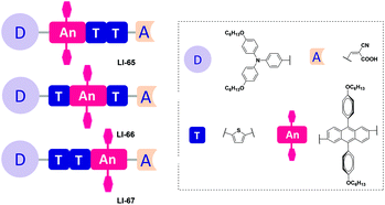
To answer this question, subtle work is needed to tune the linking positions of the isolation groups in the conjugated bridge. Thus, we present a series of anthracene-based sensitizers with flexible positioning of the two isolation groups, with the aim to explore the most suitable position for the isolation groups, alleviate the strong intermolecular interactions, and prevent the I3− anion from approaching the surface of TiO2. Hexyloxy-substituted triphenylamine and cyanoacetic acid served as the donor and acceptor, respectively (Fig. 2). To understand the influence of these fine structural variations on the photovoltaic performance, we studied their photophysical, electrochemical and photovoltaic properties in detail. LI-66, bearing the isolation groups in the middle of the conjugated bridge and a conjugated sequence of thiophene–anthracene–thiophene, gave the best performance: a Jsc value of 12.95 mA cm−2, a Voc value of 722 mV, a FF of 0.69 and a η value of 6.44%.
Results and discussion
Synthesis
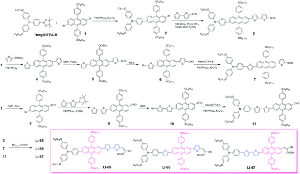
The synthetic route to the sensitizers is depicted in Scheme 1. Compound 2 was prepared through a Suzuki coupling reaction between compound 1 and HexylOTPA-B, in the presence of K2CO3 and Pd(PPh3)4. Then, by a direct arylation reaction with a catalytic system of Pd(OAc)2/PCy3·HBF4/pivalic acid, the key aldehyde, compound 3, was obtained in a moderate yield of 41.3%. A similar aldehyde, compound 7, was synthesized according to our previous work,26 by subsequent Stille coupling reaction, Vilsmeier reaction, bromination reaction and Suzuki coupling reaction. Compound 8 was obtained in moderate yield by controlling the ratio of compound 1 and n-BuLi (1![[thin space (1/6-em)]](https://www.rsc.org/images/entities/char_2009.gif) :
:![[thin space (1/6-em)]](https://www.rsc.org/images/entities/char_2009.gif) 1), then through a sequence of Suzuki coupling reaction, bromination reaction and Suzuki coupling reaction, the target aldehyde 11 was obtained. Finally, by a Knoevenagel condensation reaction between the aldehydes (compound 3, 7 and 11) and cyanoacetic acid in the presence of ammonium acetate, the target sensitizers (LI-65, LI-66 and LI-67) were obtained successfully. Their structures and purity were confirmed by 1H NMR, 13C NMR, MS and EA.
1), then through a sequence of Suzuki coupling reaction, bromination reaction and Suzuki coupling reaction, the target aldehyde 11 was obtained. Finally, by a Knoevenagel condensation reaction between the aldehydes (compound 3, 7 and 11) and cyanoacetic acid in the presence of ammonium acetate, the target sensitizers (LI-65, LI-66 and LI-67) were obtained successfully. Their structures and purity were confirmed by 1H NMR, 13C NMR, MS and EA.
Optical and electrochemical properties
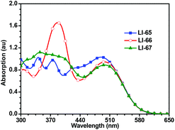
Fig. 3 shows the UV-Vis absorption spectra of the sensitizers in dilute CH2Cl2 solutions, and the related data are presented in Table 1. Benefitting from extensive π-conjugation, all the sensitizers exhibit a broad absorption range (300–600 nm). There is no obvious deep valley in the absorption curves, suggesting excellent light-harvesting abilities for the sensitizers. The maximum absorption wavelengths of the three sensitizers, which exhibit an ICT effect, are similar to each other (490, 499 and 499 nm). This is due to the sensitizers all featuring the same components of the conjugated bridge (two thiophene moieties and one 2,6-linked anthracene unit), and the same donor and acceptor moieties. However, the other peaks in their absorption spectra are different, which should be attributed to the π–π* transitions, indicating that the sequence of conjugated moieties affects part of the electron transition along the molecules. LI-66, in which the conjugated bridge features the sequence of thiophene–anthracene–thiophene, has the highest molar extinction coefficient (ε) in the region of 370–420 nm. The absorption spectra of the dye-loading TiO2 films are shown in Fig. S6.† Both the shape and intensity of the absorption curves were similar, suggesting that the light-harvesting abilities of these dye loaded films were also similar. The absorption spectra become broader and red-shifted compared to those in solution, which should be attributed to the interactions between TiO2 and the sensitizers, similar to the phenomena reported in the literature.26,35 Once the dyes are adsorbed on the surface of TiO2, the carboxylate group coordinates with the Ti4+, and lowers the π* energy level of the sensitizers, resulting in red-shifted absorption spectra.| Dye |
λ
max![[thin space (1/6-em)]](https://www.rsc.org/images/entities/char_2009.gif) a (nm) a (nm) |
ε
max![[thin space (1/6-em)]](https://www.rsc.org/images/entities/char_2009.gif) a (104 M−1 cm−1) a (104 M−1 cm−1) |
E
D/D
+![[thin space (1/6-em)]](https://www.rsc.org/images/entities/char_2009.gif) b (V) b (V) |
E
0–0![[thin space (1/6-em)]](https://www.rsc.org/images/entities/char_2009.gif) c (eV) c (eV) |
E
D*/D
+![[thin space (1/6-em)]](https://www.rsc.org/images/entities/char_2009.gif) d (V) d (V) |
E
HOMO![[thin space (1/6-em)]](https://www.rsc.org/images/entities/char_2009.gif) e (eV) e (eV) |
E
LUMO![[thin space (1/6-em)]](https://www.rsc.org/images/entities/char_2009.gif) e (eV) e (eV) |
|---|---|---|---|---|---|---|---|
| a Absorption spectra of sensitizers measured in CH2Cl2 with a concentration of 3 × 10⁻⁵ mol L−1. b The ground-state redox potential (ED/D+) was measured in CH2Cl2 with 0.1 M (n-C4H9)4NPF6 as electrolyte (scanning rate, 100 mV s−1; working electrode and counter electrode, Pt wires; reference electrode, Ag/AgCl) with Fc as an external reference. c The bandgap E0–0 was derived from the observed optical edge. d The excited-state redox potential (ED*/D+) was estimated by equation ED*/D+ = ED/D+ + E0–0/e without considering any entropy change during the light excitation. e E HOMO = −(Eox (vs. Fc/Fc+) + 4.8 eV), ELUMO = EHOMO + E0–0. | |||||||
| LI-65 | 490 | 3.44 | 0.19 | 2.11 | −1.92 | −4.99 | −2.88 |
| LI-66 | 499 | 3.15 | 0.16 | 2.11 | −1.95 | −4.96 | −2.85 |
| LI-67 | 499 | 2.97 | 0.16 | 2.11 | −1.95 | −4.96 | −2.85 |
Apart from the light absorption properties of the sensitizers, the energy-offset of the dye molecules with respect to the TiO2 film and electrolytes also plays a pivotal role in determining subsequent dynamic processes such as exciton dissociation and long-range charge separation at the TiO2/dye/electrolyte interface, which may also have a profound influence on the photovoltaic performance. The electrochemical properties of the sensitizers were studied by cyclic voltammetry methods (Fig. S7†). As listed in Table 1, the ground-state redox potentials (ED/D+) of the three sensitizers were 0.19 V for LI-65, 0.16 V for LI-66, and 0.16 V for LI-67, against the standard ferrocence/ferrocenium (Fc/Fc+) redox couple. The lower value of LI-65 may be related to the conjugated bridge. Since in LI-65 the anthracene moiety is linked to the donor directly, the electrons are easily delocalized from the donor to the extensive planar π-conjugation system of the anthracene unit. On the basis of the zero–zero transition energies (E0–0) estimated from the observed optical edge, we calculated the excited state redox potential via the equation ED*/D+ = ED/D+ + E0–0/e, as −1.92, −1.95 and −1.95 V for LI-65–LI-67, respectively. Practically, the highest occupied molecular orbital (HOMO) and lowest unoccupied molecular orbital (LUMO) levels, corresponding to ED/D+ and ED*/D+, respectively, were used to evaluate the thermodynamic feasibility of the regeneration of oxidized sensitizers and the electron injection from the sensitizers to the conduction band of TiO2. As shown in Table 1, The HOMO energy levels (EHOMO) of LI-65, LI-66 and LI-67 can be calculated by the equation above, as −4.99, −4.96 and −4.96 eV, respectively, and the LUMO energy levels (ELUMO) were in the range of −2.88 to −2.85 eV. Since an over-potential of 0.2 V is sufficient for the electron injection and 0.3 V for sensitizer regeneration, the three sensitizers are energetically permitted to function in DSCs from driving force calculations.
Theoretical approach
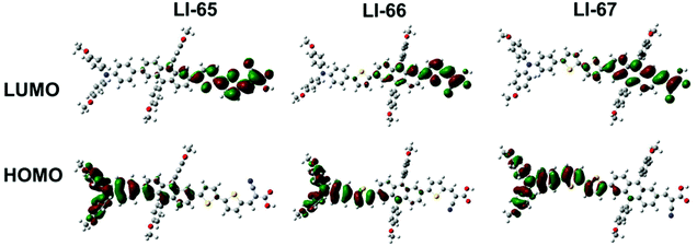
To gain insight into the geometrical and electronic structure of the sensitizers, we carried out the optimization of molecular structure and molecular orbital calculations based on DFT calculations by using the Gaussian 09 program at the B3LYP/6-31G* level.36 As expected, the D-π-A conjugation system of the three sensitizers maintained a planar geometry, benefitting from the unique properties of the 2,6-linked anthracene, and the dihedral angles between the anthracene plane and its adjacent units were about 20° (Fig. S8†). The planarity of the conjugation system enhanced the electron communication between the donor and acceptor, thus facilitating the ICT effect. On the other hand, there was a large torsion between the anthracene plane and the lateral aromatic units with dihedral angles above 70° (Fig. S8†), due to steric repulsion. The three-dimensional configuration of 9,10-diarylsubstituted anthracene was expected to weaken the strong intermolecular π–π interactions of the sensitizers. The HOMOs and LUMOs of the three sensitizers are shown in Fig. 4. It can be seen that the sequence of the π-conjugated fragments influenced the distribution of the electron densities of the frontier orbitals in some degree. For the three sensitizers with D-π-A structure, the HOMO is mainly delocalized on the donor part and only slightly localised over part of the conjugated bridge. The LUMO is predominantly concentrated on the acceptor and the adjacent units. When the 9,10-diarylsubstituted anthracene unit moves from close to the donor group to near the acceptor part (from LI-65 to LI-67), the electron distribution of the LUMO on the anthracene unit increased, and the electron density on the anchoring group decreased (Fig. 4). The overlap of the HOMO and LUMO may even be beneficial, leading to an efficient ICT, but the distance of the charge transfer in the whole molecule becomes smaller, which is unfavorable to the electron injection from the anchoring unit (the acceptor) to the TiO2 film.37,38LI-66 with the 9,10-diarylsubstituted anthracene in the middle might give a good balance of the two effects.Photovoltaic performance of DSCs
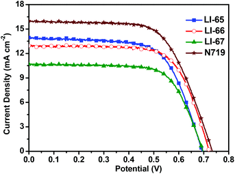
The photovoltaic performances of the sensitizers were tested with a sandwich-type DSC, employing an acetonitrile based electrolyte that consisted of LiI (0.1 M), I2 (0.05 M), dimethylpropylimidazolium iodide (0.6 M) and 4-tertbutylpyridine (0.5 M). Fig. 5 shows the monochromatic incident photon-to-current conversion efficiency (IPCE) plots as a function of the wavelength for the DSCs based on the sensitizers LI-65, LI-66 and LI-67. Benefiting from the excellent ICT effect of the whole molecules, the IPCE spectral plots of the sensitizers were broad spanning the region from 320 nm to 700 nm. It is interesting to note that the IPCE values were related to the distance between the donor and the anthracene unit, in the order of LI-65 > LI-66 > LI-67. Since the absorption spectra of their dye-load films were similar (Fig. S6†), the different electron injection efficiencies might account for the trend, which agrees with the theoretical calculations mentioned above. Fig. 6 shows the J–V plots of the sensitizers LI-65, LI-66, LI-67 and the reference dye N719 measured at simulated 100 mW cm−2 AM1.5 conditions, and the parameters are presented in Table 2. The Jsc values of the DSCs fabricated with LI-65, LI-66 and LI-67 were 13.95, 12.95 and 10.68 mA cm−2, respectively, indicating that the enhancement in the Jsc value was in accord with the decrease of the distance between the donor and the anthracene unit. It was also due to the different electron injection efficiencies for the three sensitizers, in agreement with the IPCE plots.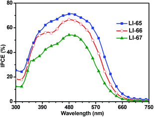 | ||
| Fig. 5 Spectra of monochromatic incident photon-to-current conversion efficiency (IPCE) for DSCs based on these sensitizers. | ||
| Dye | V oc (mV) | J sc (mA cm−2) | FF | η (%) | R rec (Ω) | τ n (ms) |
|---|---|---|---|---|---|---|
| LI-65 | 695 | 13.95 | 0.65 | 6.34 | 31.49 | 7.5 |
| LI-66 | 722 | 12.95 | 0.69 | 6.44 | 61.19 | 13.2 |
| LI-67 | 698 | 10.68 | 0.69 | 5.15 | 47.74 | 8.2 |
| N719 | 734 | 16.00 | 0.64 | 7.53 | — | — |
Although LI-65 showed the highest Jsc value among the three sensitizers, the best efficiency was achieved by LI-66 with a Jsc of 12.95 mA cm−2, a Voc of 722 mV and a FF of 0.69, corresponding to a η of 6.44%, owing to the higher Voc value (722 mV) in comparison with LI-65 (695 mV) and LI-67 (698 mV), which may be related to the degree of dye aggregation and electron recombination on the TiO2 surface. The results hinted that the isolation groups in the middle of the conjugated bridge would help to suppress the two undesired effects more effectively than those at the other sites. Thus, we can conclude that the isolation groups in the different positions of the sensitizers have little influence on the ICT effect of the whole molecule, but can affect the electron injection efficiencies of the sensitizers, due to the change of their LUMOs. Furthermore, the positioning of the isolation groups may have some influence on the alignment of the sensitizers on the TiO2 surface, resulting in the different Voc values. This was further confirmed by electrochemical impedance spectroscopy measurements (EIS). Generally, the Voc is closely related to the interfacial charge transfer processes and the electron lifetime (τn) in the TiO2 film. We carried out EIS measurements in the dark under a forward bias of −0.70 V (frequency range: 10−1–105 Hz) to elucidate the relationship between the Voc and the molecular structure. Both the Nyquist and Bode plots of the DSCs are presented in Fig. 7, and the related parameters, which could be obtained by fitting the curves with Z-view software, are collected in Table 2. In Fig. 7(A), two semicircles are observed for each sensitizer: the one at the lower frequency is related to the charge transfer at the counter electrode, and the other one located at the middle frequency is related to the charge transfer at the interface of the TiO2/electrolyte. As the devices were fabricated under similar conditions, the resistances of charge transfer at the counter electrode were almost the same. However, the resistances of charge recombination (Rrec) at the interface of TiO2/electrolyte were different, which is ascribed to the different interface characteristics of the dye-loading films. Once the sensitizers were adsorbed on the surface of TiO2, a blocking layer formed to retard the charge recombination between the electrolyte and the electrons in the TiO2 film. The value of Rrec reflects the properties of the blocking layer, the larger the Rrec, the more compact the blocking layer. In this system, LI-66 presented the largest value of Rrec (61.19 Ω) among the three sensitizers, indicating that LI-66 could retard the interfacial charge recombination more effectively than LI-65 (Rrec: 31.49 Ω) or LI-67 (Rrec: 47.74 Ω). This is in agreement with the trend in Voc, suggesting that the introduction of the lateral 4-hexyloxyphenyl units as the isolation group in the middle of the π-bridge is the most suitable position for the anthracene-based sensitizers to assemble in a compact layer to retard the interfacial charge recombination. Fig. 7(B) shows the Bode plots of DSCs based on the sensitizers, whose peak reciprocal is related with electron lifetime (τn). The calculated electron lifetime of LI-66 (13.2 ms) was longer than for LI-65 (7.5 ms) and LI-67 (8.2 ms), which was also in keeping with the trend in Voc. The longer electron lifetime of the sensitizers in the TiO2 film meant more chance for the electrons to arrive at the electrode, which was beneficial to the enhancement of photovoltaic performance. Also, it partly depended on the arrangement of the sensitizers on the TiO2 surface, and therefore the isolation groups at the center of the conjugated bridge were a good choice to improve the interface engineering of DSCs.
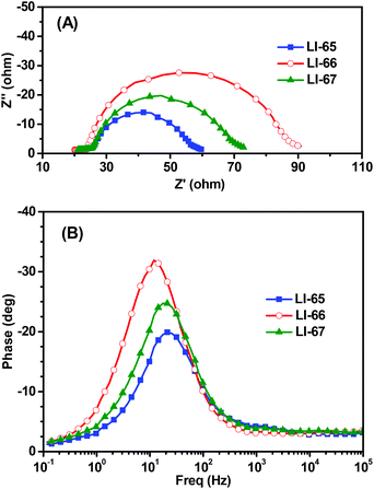 | ||
| Fig. 7 Electrochemical impedance spectroscopy (EIS) for DSCs based on the sensitizers. (A) Nyquist plots in the dark, (B) Bode phase plots in the dark. | ||
In addition, we also attempted to improve the photovoltaic performance of solar cells by the introduction of the co-adsorbent CDCA (chenodeoxycholic acid). CDCA is a nonchromophoric co-adsorbent, which is usually employed to suppress the formation of dye aggregates, thus resulting in an improved performance. Actually, common organic sensitizers, especially those with a fused ring as the conjugated bridge, usually tend to aggregate on the surface of TiO2, due to the strong π–π intermolecular interactions. Thus, the introduction of CDCA suppressed the dye aggregates improving the photovoltaic performance. Interestingly, for the three sensitizers featuring 9,10-diarylsubstituted anthracene as part of the π-bridge, through co-adsorption with CDCA (10 mM), the conversion efficiency of the corresponding DSCs (Table S1†) decreased, suggesting that almost no severe dye aggregates formed on the surface of TiO2, further confirming the function of the isolation groups in the conjugated bridge.
Conclusions
In summary, we have developed a series of 9,10-diarylsubstituted anthracene-bridged sensitizers, with the aim to investigate the positioning of the two substituted aromatic rings on the anthracene unit, which acted as the isolation groups. Our results suggested that the position of the isolation groups had little influence on the LHEs of the solar cells. However, the Jsc values of the corresponding DSCs depended on the position of the isolation groups. When the isolation group was near the donor part, with a shortened distance between the donor and the anthracene unit, the value of Jsc increased based on the LI-65-sensitized solar cell. However, EIS revealed that the isolation groups in the middle of the π-bridge can suppress the charge recombination more efficiently, leading to an enhanced Voc value of 722 mV. LI-66 exhibited the highest conversion efficiency (6.44%) with the most suitable positioning of the isolation groups in the middle of the conjugated bridge. Our results demonstrate that this may be an effective way to achieve excellent photovoltaic performance in DSCs by tuning the position of the isolation groups and the sequence of the components in the conjugated bridge.Experimental section
Materials and Instrumentation
4,4,5,5-Tetramethyl-2-{4-[N,N-bis(4-hexyloxyphenyl)amino]phenyl}-1,3,2-dioxaborolane (HexylOTPA-B), 2,6-dibromo-9,10-bis(4-hexyloxyphenyl)anthracene (1) and 2-(tributylstannyl) thiophene were prepared according to reported literature procedures.13,26,39 All solvents used were treated with standard procedures. All other reagents were used as received.The NMR spectra were recorded with a Varian Mercury 300 spectrometer. The CV spectra were measured on a Finnigan LCQ electrode, counterelectrode, and reference electrode, respectively, at a scanning rate of 100 mV s−1. The supporting electrolyte consisted of 0.1 M tetrabutylammonium hexafluorophosphate (TBAPF6) in nitrogen-purged anhydrous CH2Cl2. Elemental analyses were performed by a 73 CARLOERBA-1106 microelemental analyzer. HRMS spectra were measured on a Waters Micromass LCT Premier XE mass spectrometer. The EI mass spectra were measured on a ZAB 3F-HF mass spectrometer. The ESI mass spectra were measured on a Finnigan LCQ advantage mass spectrometer. UV-visible spectra were obtained using a Shimadzu UV-2550 spectrometer.
![[double bond, length as m-dash]](https://www.rsc.org/images/entities/char_e001.gif) ), 7.94 (s, 1H, ArH), 7.83 (s, 1H, ArH), 7.77–7.70 (m, 2H, ArH), 7.60–7.55 (m, 2H, ArH), 7.47 (d, J = 9.0 Hz, 1H, ArH), 7.41–7.28 (m, 7H, ArH), 7.19–7.16 (m, 4H, ArH), 7.10 (d, J = 7.5 Hz, 2H, ArH), 7.01 (d, J = 8.1 Hz, 4H, ArH), 6.88 (d, J = 7.5 Hz, 2H, ArH), 6.79 (d, J = 8.7 Hz, 4H, ArH), 4.16–4.10 (m, 4H, –OCH2–), 3.90 (t, J = 6.3 Hz, 4H, –OCH2–), 1.90 (s, br, 4H, –CH2–), 1.78–1.73 (m, 4H, –CH2–), 1.56 (s, br, 4H, –CH2–), 1.43–1.33 (m, 20H, –CH2–), 0.95–0.91 (m, 12H, –CH3). 13C NMR (CDCl3) δ (ppm): 168.12, 158.73, 158.55, 155.46, 148.45, 146.99, 140.35, 136.92, 136.64, 134.35, 133.42, 132.55, 131.01, 130.27, 129.83, 129.76, 128.76, 128.07, 127.98, 127.90, 127.71, 127.59, 127.31, 126.69, 124.37, 123.92, 123.01, 122.94, 122.75, 119.93, 115.51, 115.39, 114.52, 114.41, 94.63, 68.22, 31.87, 31.71, 29.59, 29.40, 26.01, 25.85, 22.81, 22.79, 22.71, 14.24. HRMS (ESI, m/z): [M + H]+ calcd for C80H85N2O6S2: 1233.5849. Found: 1233.5841. Anal. Calcd for C80H84N2O6S2: C, 77.89; H, 6.86; N, 2.27. Found: C, 77.48; H, 7.23; N, 2.34.
), 7.94 (s, 1H, ArH), 7.83 (s, 1H, ArH), 7.77–7.70 (m, 2H, ArH), 7.60–7.55 (m, 2H, ArH), 7.47 (d, J = 9.0 Hz, 1H, ArH), 7.41–7.28 (m, 7H, ArH), 7.19–7.16 (m, 4H, ArH), 7.10 (d, J = 7.5 Hz, 2H, ArH), 7.01 (d, J = 8.1 Hz, 4H, ArH), 6.88 (d, J = 7.5 Hz, 2H, ArH), 6.79 (d, J = 8.7 Hz, 4H, ArH), 4.16–4.10 (m, 4H, –OCH2–), 3.90 (t, J = 6.3 Hz, 4H, –OCH2–), 1.90 (s, br, 4H, –CH2–), 1.78–1.73 (m, 4H, –CH2–), 1.56 (s, br, 4H, –CH2–), 1.43–1.33 (m, 20H, –CH2–), 0.95–0.91 (m, 12H, –CH3). 13C NMR (CDCl3) δ (ppm): 168.12, 158.73, 158.55, 155.46, 148.45, 146.99, 140.35, 136.92, 136.64, 134.35, 133.42, 132.55, 131.01, 130.27, 129.83, 129.76, 128.76, 128.07, 127.98, 127.90, 127.71, 127.59, 127.31, 126.69, 124.37, 123.92, 123.01, 122.94, 122.75, 119.93, 115.51, 115.39, 114.52, 114.41, 94.63, 68.22, 31.87, 31.71, 29.59, 29.40, 26.01, 25.85, 22.81, 22.79, 22.71, 14.24. HRMS (ESI, m/z): [M + H]+ calcd for C80H85N2O6S2: 1233.5849. Found: 1233.5841. Anal. Calcd for C80H84N2O6S2: C, 77.89; H, 6.86; N, 2.27. Found: C, 77.48; H, 7.23; N, 2.34.
![[double bond, length as m-dash]](https://www.rsc.org/images/entities/char_e001.gif) CH–), 7.98 (s, 1H, ArH), 7.93 (s, 1H, ArH), 7.76–7.74 (m, 3H, ArH), 7.65–7.62 (m, 3H, ArH), 7.38–7.28 (m, 8H, ArH), 7.15 (d, J = 7.2 Hz, 4H, ArH), 6.96 (d, J = 7.5 Hz, 4H, ArH), 6.85 (d, J = 8.1 Hz, 4H, ArH), 6.70 (d, J = 8.1 Hz, 2H, ArH), 4.07 (s, br, 4H, –OCH2–), 3.89 (s, br, 4H, –OCH2–), 1.77 (s, br, 4H, –CH2–), 1.68 (s, br, 4H, –CH2–), 1.35–1.30 (m, 24H, –CH2–), 0.87 (s, br, 12H, –CH3). 13C NMR (CDCl3) δ (ppm): 167.65, 158.82, 158.71, 155.45, 147.60, 144.40, 141.61, 139.95, 137.87, 136.71, 134.28, 132.81, 132.58, 132.40, 131.04, 130.96, 130.32, 129.84, 129.72, 129.56, 128.16, 126.61, 125.77, 125.39, 124.46, 123.96, 123.13, 119.30, 115.31, 115.04, 114.85, 114.48, 68.22, 32.00, 31.84, 29.71, 29.51, 26.14, 25.95, 22.94, 22.82, 14.35. HRMS (ESI, m/z): [M + H]+ calcd for C80H85N2O6S2: 1233.5849. Found: 1233.5850. Anal. Calcd for C80H84N2O6S2: C, 77.89; H, 6.86; N, 2.27. Found: C, 77.40; H, 6.50; N, 2.37.
CH–), 7.98 (s, 1H, ArH), 7.93 (s, 1H, ArH), 7.76–7.74 (m, 3H, ArH), 7.65–7.62 (m, 3H, ArH), 7.38–7.28 (m, 8H, ArH), 7.15 (d, J = 7.2 Hz, 4H, ArH), 6.96 (d, J = 7.5 Hz, 4H, ArH), 6.85 (d, J = 8.1 Hz, 4H, ArH), 6.70 (d, J = 8.1 Hz, 2H, ArH), 4.07 (s, br, 4H, –OCH2–), 3.89 (s, br, 4H, –OCH2–), 1.77 (s, br, 4H, –CH2–), 1.68 (s, br, 4H, –CH2–), 1.35–1.30 (m, 24H, –CH2–), 0.87 (s, br, 12H, –CH3). 13C NMR (CDCl3) δ (ppm): 167.65, 158.82, 158.71, 155.45, 147.60, 144.40, 141.61, 139.95, 137.87, 136.71, 134.28, 132.81, 132.58, 132.40, 131.04, 130.96, 130.32, 129.84, 129.72, 129.56, 128.16, 126.61, 125.77, 125.39, 124.46, 123.96, 123.13, 119.30, 115.31, 115.04, 114.85, 114.48, 68.22, 32.00, 31.84, 29.71, 29.51, 26.14, 25.95, 22.94, 22.82, 14.35. HRMS (ESI, m/z): [M + H]+ calcd for C80H85N2O6S2: 1233.5849. Found: 1233.5850. Anal. Calcd for C80H84N2O6S2: C, 77.89; H, 6.86; N, 2.27. Found: C, 77.40; H, 6.50; N, 2.37.
![[double bond, length as m-dash]](https://www.rsc.org/images/entities/char_e001.gif) and ArH), 8.02 (s, 1H, ArH), 7.83–7.79 (m, 2H, ArH), 7.72 (d, J = 8.4 Hz, 1H, ArH), 7.43–7.38 (m, 6H, ArH), 7.34 (d, J = 3.9 Hz, 1H, ArH), 7.25–7.19 (m, 8H, ArH), 7.01 (s, br, 4H, ArH), 6.86–6.83 (m, 6H, ArH), 4.18–4.12 (m, 4H, –OCH2–), 3.94 (t, J = 6.0 Hz, 4H, ArH), 1.92–1.87 (m, 4H, –CH2–), 1.60 (s, br, 4H, –CH2–), 1.49–1.36 (m, 24H, –CH2–), 0.96–0.92 (m, 12H, –CH2–). 13C NMR (d8-THF) δ (ppm): 163.76, 160.09, 160.01, 156.76, 154.22, 149.57, 144.66, 142.90, 141.08, 140.48, 138.75, 138.04, 135.89, 135.40, 133.00, 132.64, 132.21, 130.91, 130.42, 130.28, 129.96, 129.81, 129.08, 128.94, 127.40, 126.70, 126.50, 125.91, 125.66, 124.99, 124.55, 123.41, 123.04, 122.83, 120.77, 116.16, 115.86, 115.35, 104.13, 68.60, 32.49, 32.41, 30.16, 26.60, 23.38, 14.25. HRMS (ESI, m/z): [M + H]+ calcd for C80H85N2O6S2: 1233.5849. Found: 1233.5841. Anal. Calcd for C80H84N2O6S2: C, 77.89; H, 6.86; N, 2.27. Found: C, 77.44; H, 6.60; N, 2.43.
and ArH), 8.02 (s, 1H, ArH), 7.83–7.79 (m, 2H, ArH), 7.72 (d, J = 8.4 Hz, 1H, ArH), 7.43–7.38 (m, 6H, ArH), 7.34 (d, J = 3.9 Hz, 1H, ArH), 7.25–7.19 (m, 8H, ArH), 7.01 (s, br, 4H, ArH), 6.86–6.83 (m, 6H, ArH), 4.18–4.12 (m, 4H, –OCH2–), 3.94 (t, J = 6.0 Hz, 4H, ArH), 1.92–1.87 (m, 4H, –CH2–), 1.60 (s, br, 4H, –CH2–), 1.49–1.36 (m, 24H, –CH2–), 0.96–0.92 (m, 12H, –CH2–). 13C NMR (d8-THF) δ (ppm): 163.76, 160.09, 160.01, 156.76, 154.22, 149.57, 144.66, 142.90, 141.08, 140.48, 138.75, 138.04, 135.89, 135.40, 133.00, 132.64, 132.21, 130.91, 130.42, 130.28, 129.96, 129.81, 129.08, 128.94, 127.40, 126.70, 126.50, 125.91, 125.66, 124.99, 124.55, 123.41, 123.04, 122.83, 120.77, 116.16, 115.86, 115.35, 104.13, 68.60, 32.49, 32.41, 30.16, 26.60, 23.38, 14.25. HRMS (ESI, m/z): [M + H]+ calcd for C80H85N2O6S2: 1233.5849. Found: 1233.5841. Anal. Calcd for C80H84N2O6S2: C, 77.89; H, 6.86; N, 2.27. Found: C, 77.44; H, 6.60; N, 2.43.
Device fabrication and photovoltaic properties measurements
The preparation and treatment of the TiO2 films, which were composed of a transparent TiO2 layer (12 μm) and a scattering layer (4 μm), were similar to the reported literature procedures.30 The dye loading was realized by immersing the films into 0.3 mM CHCl3/CH3CN/t-BuOH (1/2/2) solutions of LI-65, LI-66 and LI-67 for 24 h under dark. For the co-adsorption, before being immersed in the corresponding dye solutions, the films were pretreated with the ethanol solution of CDCA for 6 h. The counter electrode was prepared by spinning a 20 mM solution of H2PtCl6 in isoamyl alcohol onto a FTO glass. Then the photo-anode and counter electrode were integrated together by using a hot-melt ionomer film (25 μm) and heated at 110 °C with pressure for 30 s. The electrolyte, which was composed of 0.1 M lithium iodide, 0.6 M dimethylpropyl-imidazolium iodide (DMPII), 0.05 M I2, 0.1 M LiI and 0.5 M 4-tert-butylpyridine (4-TBP) in acetonitrile, was injected into a drilled hole in the counter electrode with the help of vacuum backfilling. Finally, the hole was sealed with a piece of tape.The photovoltaic properties measurements were similar to those reported previously.40
Acknowledgements
We are grateful to the National Science Foundation of China (no. 21372003, 21325416), and the National Fundamental Key Research Program (2013CB834701) for financial support.Notes and references
- A. Hagfeldt, G. Boschloo, L. Sun, L. Kloo and H. Pettersson, Chem. Rev., 2010, 110, 6595 CrossRef CAS PubMed.
- S. Zhang, X. Yang, Y. Numata and L. Han, Energy Environ. Sci., 2013, 6, 1443 CAS.
- S. Zhang, A. Islam, X. Yang, C. Qin, K. Zhang, Y. Numata, H. Chen and L. Han, J. Mater. Chem. A, 2013, 1, 4812 CAS.
- Q. Chai, W. Li, Y. Wu, K. Pei, J. Liu, Z. Geng, H. Tian and W. Zhu, ACS Appl. Mater. Interfaces, 2014, 6, 14621 CAS.
- A. Mishra, M. K. Fischer and P. Bauerle, Angew. Chem., Int. Ed., 2009, 48, 2474 CrossRef CAS PubMed.
- M. K. Nazeeruddin, F. De Angelis, S. Fantacci, A. Selloni, G. Viscardi, P. Liska, S. Ito, B. Takeru and M. Grätzel, J. Am. Chem. Soc., 2005, 127, 16835 CrossRef CAS PubMed.
- B. S. Chen, K. Chen, Y. H. Hong, W. H. Liu, T. H. Li, C. H. Lai, P. T. Chou, Y. Chi and G. H. Lee, Chem. Commun., 2009, 5844 RSC.
- H. Ozawa, Y. Okuyama and H. Arakawa, ChemPhysChem, 2014, 15, 1201 CrossRef CAS PubMed.
- S. Mathew, A. Yella, P. Gao, R. Humphry-Baker, F. E. Curchodbasile, N. Ashari-Astani, I. Tavernelli, U. Rothlisberger, K. Nazeeruddinmd and M. Grätzel, Nat. Chem., 2014, 6, 242 CrossRef CAS PubMed.
- K. Kakiage, Y. Aoyama, T. Yano, T. Otsuka, T. Kyomen, M. Unno and M. Hanaya, Chem. Commun., 2014, 50, 6379 RSC.
- Z. Yao, M. Zhang, H. Wu, L. Yang, R. Li and P. Wang, J. Am. Chem. Soc., 2015, 137, 3799 CrossRef CAS PubMed.
- J. Yang, P. Ganesan, J. Teuscher, T. Moehl, Y. J. Kim, C. Yi, P. Comte, K. Pei, T. W. Holcombe, M. K. Nazeeruddin, J. Hua, S. M. Zakeeruddin, H. Tian and M. Grätzel, J. Am. Chem. Soc., 2014, 136, 5722 CrossRef CAS PubMed.
- N. Zhou, K. Prabakaran, B. Lee, S. H. Chang, B. Harutyunyan, P. Guo, M. R. Butler, A. Timalsina, M. J. Bedzyk, M. A. Ratner, S. Vegiraju, S. Yau, C.-G. Wu, R. P. H. Chang, A. Facchetti, M.-C. Chen and T. J. Marks, J. Am. Chem. Soc., 2014, 137, 4414 CrossRef PubMed.
- Y. Xie, Y. Tang, W. Wu, Y. Wang, J. Liu, X. Li, H. Tian and W.-H. Zhu, J. Am. Chem. Soc., 2015, 137, 14055 CrossRef CAS PubMed.
- M. Liang and J. Chen, Chem. Soc. Rev., 2013, 42, 3453 RSC.
- Z. Chai, M. Wu, M. Fang, S. Wan, T. Xu, R. Tang, Y. Xie, A. Mei, H. Han, Q. Li and Z. Li, Adv. Energy Mater., 2015, 5, 201500846 Search PubMed.
- J. Shi, Z. Chai, R. Tang, J. Hua, Q. Li and Z. Li, Sci. China: Chem., 2015, 58, 1144 CrossRef CAS.
- Z. Ning, Q. Zhang, W. Wu, H. Pei, B. Liu and H. Tian, J. Org. Chem., 2008, 73, 3791 CrossRef CAS PubMed.
- Z. Ning, Q. Zhang, H. Pei, J. Luan, C. Lu, Y. Cui and H. Tian, J. Phys. Chem. C, 2009, 113, 10307 CAS.
- N. Koumura, Z. S. Wang, S. Mori, M. Miyashita, E. Suzuki and K. Hara, J. Am. Chem. Soc., 2008, 130, 4202 CrossRef CAS.
- Q. Li, L. Lu, C. Zhong, J. Huang, Q. Huang, J. Shi, X. Jin, T. Peng, J. Qin and Z. Li, Chem. – Eur. J., 2009, 15, 9664 CrossRef CAS PubMed.
- H. Li, Y. Hou, Y. Yang, R. Tang, J. Chen, H. Wang, H. Han, T. Peng, Q. Li and Z. Li, ACS Appl. Mater. Interfaces, 2013, 5, 12469 CAS.
- Q. Li, J. Shi, H. Li, S. Li, C. Zhong, F. Guo, M. Peng, J. Hua, J. Qin and Z. Li, J. Mater. Chem., 2012, 22, 6689 RSC.
- J. Shi, J. Huang, R. Tang, Z. Chai, J. Hua, J. Qin, Q. Li and Z. Li, Eur. J. Org. Chem., 2012, 5248 CrossRef CAS.
- Q. Li, L. Lu, C. Zhong, J. Shi, Q. Huang, X. Jin, T. Peng, J. Qin and Z. Li, J. Phys. Chem. B, 2009, 113, 14588 CrossRef CAS PubMed.
- H. Li, Y. Yang, Y. Hou, R. Tang, T. Duan, J. Chen, H. Wang, H. Han, T. Peng, X. Chen, Q. Li and Z. Li, ACS Sustainable Chem. Eng., 2014, 2, 1776 CrossRef CAS.
- Z. Zhao, F. Zhang, X. Zhang, X. Yang, H. Li, X. Gao, C. Di and D. Zhu, Macromolecules, 2013, 46, 7705 CrossRef CAS.
- Z. Zhao, Z. Wang, Y. Hu, X. Yang, H. Li, X. Gao and D. Zhu, J. Org. Chem., 2013, 78, 12214 CrossRef CAS PubMed.
- H. Y. Chen, C. T. Chen and C. T. Chen, Macromolecules, 2010, 43, 3613 CrossRef CAS.
- K. H. Jung, S. Y. Bae, K. H. Kim, M. J. Cho, K. Lee, Z. H. Kim, D. H. Choi, D. H. Lee, D. S. Chung and C. E. Park, Chem. Commun., 2009, 5290 RSC.
- D. a. M. Egbe, S. TüRk, S. Rathgeber, F. KüHnlenz, R. Jadhav, A. Wild, E. Birckner, G. Adam, A. Pivrikas, V. Cimrova, G. N. KnöR, N. S. Sariciftci and H. Hoppe, Macromolecules, 2010, 43, 1261 CrossRef CAS.
- R. Lin, H. W. Lin, Y. S. Yen, C. H. Chang, H. H. Chou, P. W. Chen, C. Y. Hsu, Y. C. Chen, J. T. Lin and K. C. Ho, Energy Environ. Sci., 2013, 6, 2477 Search PubMed.
- K. Ito, T. Suzuki, Y. Sakamoto, D. Kubota, Y. Inoue, F. Sato and S. Tokito, Angew. Chem., Int. Ed., 2003, 115, 1191 CrossRef.
- J. Sun, J. Chen, J. Zou, S. Ren, H. Zhong, D. Zeng, J. Du, E. Xu and Q. Fang, Polymer, 2008, 49, 2282 CrossRef CAS.
- J. He, F. Guo, X. Li, W. Wu, J. Yang and J. Hua, Chem. – Eur. J., 2012, 18, 7903 CrossRef CAS PubMed.
- M. J. Frisch, G. W. Trucks, H. B. Schlegel, G. E. Scuseria, M. A. Robb, J. R. Cheeseman, G. Scalmani, V. Barone, B. Mennucci, G. A. Petersson, H. Nakatsuji, M. Caricato, X. Li, H. P. Hratchian, A. F. Izmaylov, J. Bloino, G. Zheng, J. L. Sonnenberg, M. Hada, M. Ehara, K. Toyota, R. Fukuda, J. Hasegawa, M. Ishida, T. Nakajima, Y. Honda, O. Kitao, H. Nakai, T. Vreven, J. A. Montgomery, Jr., J. E. Peralta, F. Ogliaro, M. Bearpark, J. J. Heyd, E. Brothers, K. N. Kudin, V. N. Staroverov, R. Kobayashi, J. Normand, K. Raghavachari, A. Rendell, J. C. Burant, S. S. Iyengar, J. Tomasi, M. Cossi, N. Rega, J. M. Millam, M. Klene, J. E. Knox, J. B. Cross, V. Bakken, C. Adamo, J. Jaramillo, R. Gomperts, R. E. Stratmann, O. Yazyev, A. J. Austin, R. Cammi, C. Pomelli, J. W. Ochterski, R. L. Martin, K. Morokuma, V. G. Zakrzewski, G. A. Voth, P. Salvador, J. J. Dannenberg, S. Dapprich, A. D. Daniels, Ö. Farkas, J. B. Foresman, J. V. Ortiz, J. Cioslowski and D. J. Fox, Gaussian, Inc., Wallingford CT, 2009.
- B. G. Kim, K. Chung and J. Kim, Chem. – Eur. J., 2013, 19, 5220 CrossRef CAS PubMed.
- T. L. Bahers, T. Pauporté, P. P. Lainé, F. Labat, C. Adamo and I. Ciofini, J. Phys. Chem. Lett., 2013, 4, 1044 CrossRef PubMed.
- N. Xiang, X. Huang, X. Feng, Y. Liu, B. Zhao, L. Deng, P. Shen, J. Fei and S. Tan, Dyes Pigm., 2011, 88, 75 CrossRef CAS.
- H. Li, R. Tang, Y. Hou, Y. Yang, J. Chen, L. Liu, H. Han, T. Peng, Q. Li and Z. Li, Asian J. Org. Chem., 2014, 3, 176 CrossRef CAS.
Footnote |
| † Electronic supplementary information (ESI) available: Fig. S1–S8 and Table S1. See DOI: 10.1039/c5qo00377f |
| This journal is © the Partner Organisations 2016 |


