 Open Access Article
Controlled release kinetics from a surface modified microgel-based reservoir device
Siyuan
Guo†
,
Yongfeng
Gao†
,
Menglian
Wei
,
Qiang Matthew
Zhang
 and
Michael J.
Serpe
*
Department of Chemistry, University of Alberta, Edmonton, Alberta T6G 2G2, Canada. E-mail: michael.serpe@ualberta.ca
First published on 20th February 2015
Abstract
A device constructed by sandwiching a thin film of poly(N-isopropylacrylamide)-co-acrylic acid (pNIPAm-co-AAc) microgels between two thin layers of Au (all on a glass support) was used as a novel platform for controlled release of small molecules (drugs). In this submission, the model drug tris (4-(dimenthylamino)phenyl)methylium chloride (Crystal Violet, CV) was loaded into the microgel layer of the device by electrostatic interaction of its positive charge with the negative charges on the deprotonated AAc groups on the microgels at pH > 6.5. The upper Au layer of this device was coated with SiO2 generated by hydrolysis of tetraethyl orthosilicate (TEOS) catalyzed by ammonia at room temperature. Upon exposing the CV loaded devices to pH 3 solutions, the microgel AAc groups were neutralized, and the CV released. The release rate of the CV could be controlled by the thickness of the SiO2 layer coating the Au layer. Specifically, devices with thick silica layers slow the release rate and thin layers allow for faster release. This device represents an easily fabricated device for controlled and triggered release from a thin film with easily controlled release kinetics.
Introduction
Stimuli responsive polymer-based materials are often referred to as “smart materials” due to their ability to respond to external stimuli, e.g., temperature,1 pH,2–5 light,6–8 magnetic field,9 and electrical field.10,11 In the last few decades, functional stimuli responsive materials such as porous materials,12–14 microgels,15 and nanogels16,17 have been used to encapsulate and release small molecules (or drugs) in a controlled and triggered fashion. Among stimuli responsive polymers, poly(N-isopropylacrylamide) (pNIPAm) is by far the most extensively studied to date; a direct result of its thermoresponsivity.17–20 Specifically, pNIPAm exhibits a lower critical solution temperature (LCST) of 32 °C in water, which is close to physiological temperature. Above the LCST, pNIPAm undergoes a transition from a random coil (extended state) to a globule (collapsed state), expelling its solvating water in the process.PNIPAm can be crosslinked into a polymer network, and hydrogel particles (nanogels or microgels, depending on diameter) can be synthesized. These networks also undergo a swollen-to-collapsed transition in water at elevated temperature. Specifically, pNIPAm-based microgels transition from a swollen (large diameter) to a collapsed (small diameter) state at elevated temperature.21–23 Like all temperature induced conformational state changes of pNIPAm, the transition for pNIPAm-based microgels is fully reversible over many cycles. PNIPAm-based microgels can also be made responsive to other stimuli, in addition to temperature. For example, copolymerization of functional monomers or crosslinkers into the pNIPAm network can make them responsive to, e.g., pH, light and/or electric field.5,7,11 A well-known pH responsive pNIPAm-based microgel is pNIPAm-co-acrylic acid (pNIPAm-co-AAc), which is made by simply adding AAc at the time of synthesis.4 AAc exhibits a pKa of 4.25, therefore pNIPAm-co-AAc microgels are negatively charged at pH > 4.25, while they are neutralized at pH < 4.25. The charge switchability of the pNIPAm-co-AAc microgels allows them to bind and release positively charged molecules at pH > pKa, and pH < pKa, respectively.24
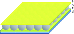
In previous work, we showed that optical devices, known as etalons, could be generated by “sandwiching” a homogeneous monolayer of pNIPAm-co-AAc microgels between two thin Au layers.4,23–32 The structure of this device can be seen in Fig. 1. The optical properties of these devices have been studied in great detail, and they have been used for sensing a variety of species.33,34 We also found that the structure could be used for controlled and triggered drug delivery. Importantly, we determined that the release rate depended greatly on the thickness of the Au layer covering the microgel layer (Au overlayer), which systematically varied the pore size. Therefore, thick Au layers slowed the release properties compared to thin Au layers.24
In those studies, we used Au layer thicknesses of up to 700 nm, which increases the device's cost and fabrication time dramatically. Therefore, new ways to control release rates are needed. In this submission, we modify the Au overlayer porosity by adding a layer of silica via the hydrolysis of tetraethyl orthosilicate (TEOS) vapor with water in the presence of ammonia. Using this approach, we were able to decrease the Au overlayer thickness to below 50 nm and subsequently modify the Au layer with silica to control the release rates. By varying the silica layer thickness by varying the modification time, the release rate could be effectively controlled and tuned, i.e., long modification time leads to slow release rates. This low-cost and effective method provides an alternative way to control and trigger drug release by using the microgel-based drug reservoir systems.
Experimental section
Materials
N-isopropylacrylamide (NIPAm) was purchased from TCI (Portland, Oregon) and purified by recrystallization from hexanes (ACS reagent grade, EMD, Gibbstown, NJ) prior to use. N,N′-Methylenebisacrylamide (BIS) (99%), acrylic acid (AAc) (99%), and ammonium persulfate (APS) (98+%) were obtained from Sigma-Aldrich (St. Louis, MO) and were used as received. Tris (4-(dimethylamino)phenyl)methylium chloride (Crystal Violet, CV) and tetraethyl orthosilicate (TEOS, 98%) were obtained from Sigma-Aldrich (St. Louis, MO). Sodium chloride was obtained from EMD (Millipore, Billerica, MA), and deionized (DI) water with a resistivity of 18.2 MΩ cm was used. Cr/Au annealing was done in a Thermolyne muffle furnace from ThermoFisher Scientific (Ottawa, Ontario). Anhydrous ethanol was obtained from Commercial Alcohols (Brampton, Ontario). Sodium hydroxide (NaOH, 99.8%) and hydrochloric acid were purchased from Caledon Chemicals (Georgetown, Ontario) and were used as received. Fisher's finest glass coverslips were 25 × 25 mm and obtained from Fisher Scientific (Ottawa, Ontario). Cr was 99.999% and obtained from ESPI as flakes (Ashland, OR), while Au was 99.99% and obtained from MRCS Canada (Edmonton, AB).Microgel synthesis
Temperature-ramp, surfactant-free, free radical precipitation polymerization was used to synthesize microgels, as previously described.35 Briefly, a 3-necked round-bottom flask was fitted with a reflux condenser, nitrogen inlet, and temperature probe, and charged with a solution of monomer mixture, comprised of NIPAm (11.9 mmol) and BIS (0.703 mmol) in 99 mL of deionized water, previously filtered through a 0.2 μm filter. The solution was bubbled with N2 while stirring and heated to 70 °C over ∼1 hour. 99 μL of AAc (1.43 mmol) was added to the heated reaction mixture with micropipette in one aliquot. The reaction was then initiated with an ammonium persulfate (APS) solution, prepared by dissolving 0.2 mmol APS in 1 mL of deionized water. The reaction was then allowed to proceed at 70 °C for 4 hours under a blanket of nitrogen and vigorous stirring. The resulting suspension was allowed to cool overnight while stirring, and then filtered through glass wool to remove any large aggregates. About 12 mL of the microgel suspension was then distributed into centrifuge tubes and washed via centrifugation at ∼8500 rcf for 45 min to form a pellet at the bottom of centrifuge tubes, followed by removal of the supernatant. And then the pellet of microgel was re-suspended with original volume, 12 mL, of deionized water. This process was repeated to a total of six times to remove any unreacted monomers. The purified microgels were recombined and stored in a brown glass jar.CV loaded etalon fabrication
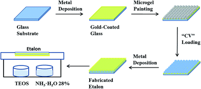
CV loaded etalons were fabricated by using a previously reported protocol with slight modification.23 The process is shown in Fig. 2. To fabricate the Au coated glass substrates (etalon underlayer), 2 nm Cr and 15 nm of Au was sequentially thermally evaporated at a rate of 0.2 Å s−1, and 0.1 Å s−1, respectively, (Torr International Inc., thermal evaporation system, Model THEUPG, New Windsor, NY) onto a 25 × 25 mm DI water–ethanol rinsed and N2 gas dried glass substrate (Fisher's Finest, Ottawa, ON). The Cr/Au coated substrates were annealed at 250 °C for 3 h (Thermolyne muffle furnace, Ottawa, ON) and cooled down to room temperature prior to microgel film painting. The annealed substrate was washed with deionized water and ethanol followed by drying with N2 gas. Then a 40 μL aliquot of the concentrated microgels was dispensed onto the substrate and then spread toward each edge using the side of a micropipette tip. The substrate was rotated 90°, and the microgel solution was spread again. The spreading and rotation continued until the microgel solution became too viscous to spread due to drying. The microgel solution was allowed to dry completely on the substrate for 2 h with the hot plate temperature set to 35 °C. After that, the dry film was rinsed copiously with DI water to remove any excess microgels not directly bound to the Au. The microgel painted substrate was then placed into a DI water bath and allowed to incubate overnight on a hot plate set to 30 °C. Following this step, the substrate was again rinsed with DI water to further remove any microgels not bound directly to the Au substrate surface. The samples were then dried with N2, and soaked in CV solution (4 mg mL−1, pH of 6.5) for 5 hours. The substrates were again rinsed with pH 6.5 solution (to maintain the microgel–CV interaction) to remove excess CV not bound to the microgels, and incubated in pH 6.5 solution for 1 hour followed by drying with N2 gas. Finally, another 2 nm Cr and 50 nm of Au metal layers were deposited on the microgel layer.Au overlayer modification with silica
Two 0.5 mL glass vessels were placed inside of a glass Petri dish. 0.4 mL of TEOS and NH3 (28% in water) were added separately into each vessel. Another Petri dish, with a CV-loaded device secured inside, was placed on top of the above Petri dish such that the Au overlayer was facing the TEOS/NH3 vessels. Parafilm was used to completely seal the system. The whole apparatus was held at room temperature, for different periods of time, to yield SiO2 (silica) layers with various thicknesses. After silica layer formation, the etalon edges were sealed with clear nail polish, to ensure CV could only exit the microgel layer through the Au/silica overlayer.CV release experiments
A Petri dish filled with 20 mL of water at pH 3 (ionic strength = 2 mM) was placed on a hot plate, and the solution temperature was maintained at 25 °C. The solution in the Petri dish was stirred continuously at 400 rpm using a magnetic stir bar. A sample was added to the Petri dish, and a peristaltic pump was used to circulate the solution through a quartz cuvette in an Agilent 8453 UV-Vis spectrophotometer, equipped with an 89090A temperature controller and Peltier heating device. The absorbance spectrum of the solution was collected every minute. The flow rate of the solution was set to a constant value, 0.042 mL s−1 (as measured).Results and discussion
PNIPAm microgel-based etalons loaded with the small molecule tris (4-(dimethylamino)phenyl)methylium chloride (Crystal Violet, CV) were generated. The procedure is outlined in Fig. 2, and detailed above. Briefly, microgels attached to a Au coated glass substrate were loaded with CV, by soaking them in a CV solution with a pH 6.5 that renders the microgels negatively charged, and the CV positively charged. This layer was subsequently coated with another layer of Cr and Au, and the “sandwich” structure exposed to TEOS for various times. The reaction of TEOS with water to form silica is shown below, and has been utilized previously for coating surfaces.36–38A schematic depiction of the silica layer generation is shown in Fig. 3. We hypothesize that the silica layer covers the surface of the Au overlayer, and fills in the Au overlayer pores to block the path of CV exiting the microgel layer to enter the surrounding solution. As the modification time is increased, the silica layer thickness should likewise increase, and more of the Au pores should be filled. The surface morphology of the resulting devices was investigated using atomic force microscopy (AFM, tapping mode, Asylum Research, Santa Barbara, CA) at room temperature. The images are shown in Fig. 4. From the images it can be seen that the microgel curvature is obvious before silica layer formation, while the curvature is diminished after silica layer formation. From the image, the apparent microgel diameter (diameter that can be measured, not necessarily the absolute diameter) before silica layer deposition was ∼500 nm, while it appears to increase to ∼700 nm as a result of silica layer deposition. The surface morphology is also clearly affected by the silica layer deposition. These observations allow us to conclude that the silica layers are forming on the Au overlayer.
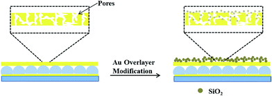 | ||
| Fig. 3 Schematic illustrating the pores in Au layers that allow CV to be transferred from the microgel layer to the system, and how this is changed by the addition of the silica layers. | ||
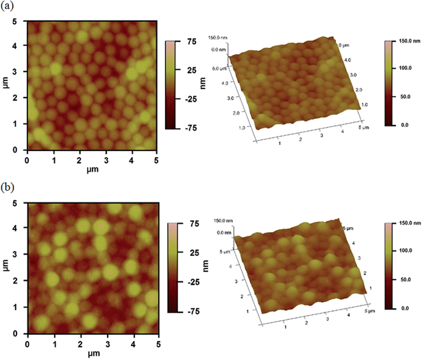 | ||
| Fig. 4 AFM images of surface morphology of the reservoir devices (a) before, and (b) after 9 h silica layer growth. | ||
X-ray photoelectron spectroscopy (XPS) was also used to confirm the elemental composition of the overlayers after silica layer deposition, and how the atomic mole percent of silicon was affected by deposition time. The signal at 104 eV from the XPS spectrum (data not shown) was used to determine the atomic mole percent of Si4+, which is evidence of the oxide state.39Fig. 5 shows that as the silica layer “growth” time increased, the amount of Si4+ also increased, with a concomitant decrease in the Au signal due to the silica layer covering it. Secondary ion mass spectrometry (SIMS) was conducted, and the data is shown in Fig. 6 for the unmodified, 3 hour modified and 9 hour modified samples. The data shows that the Si layer formation is homogenous on the Au surface. In fact, after 3 h deposition, the surface appears uniformly coated with Si, with little Au detectable over this area. The results after 9 h are similar. These data are consistent with thicker silica layers being deposited on the device's Au overlayer as a function of increasing deposition time.
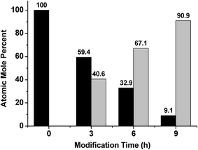 | ||
| Fig. 5 Atomic mole percent of (Black) Au and (Grey) Si as a function of modification time, as determined from XPS analysis. | ||
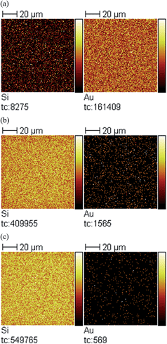 | ||
| Fig. 6 SIMS images for (left) Si and (right) Au of (a) unmodified sample, (b) 3 hour modified sample, and (c) 9 hour modified sample. Field of view is 100 × 100 μm2. | ||
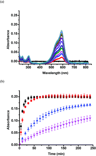
Once silica layers were deposited on the device Au overlayers, the CV release kinetics were investigated. We determined the release kinetics for devices with no silica layer, and devices after 3, 6, and 9 h TEOS exposure. These experiments were completed by adding CV loaded devices to a Petri dish containing 20 mL of pH 3.0 aqueous solutions. This pH neutralizes the microgel AAc groups allowing the CV to exit the devices. Solution from the Petri dish was pumped into a cuvette held in a UV-Vis spectrometer, which was setup acquire a spectrum every 1 min for 240 min (4 h). The flow rate of the liquid was fixed at a constant value of 0.042 mL s−1. CV, a water soluble dye, has a maximum absorbance at ∼590 nm. Therefore, based on Beers' law, and the constant solution volume, the magnitude of the absorbance at 590 nm is proportional to the amount of CV released. Representative UV-Vis absorbance spectra from the 3 h modified sample are shown in Fig. 7a. Fig. 7b shows the full set of release kinetics. As is clearly seen, the release kinetics from the unmodified device is much faster than the modified devices. The device exposed to TEOS for 9 h clearly has the slowest release kinetics, releasing only half the CV that the unmodified devices do in the given time period. Control experiments were completed with devices exposed to TEOS – in this case, the devices didn't have the upper Au layer coating the microgels. We observed no effect on the release kinetics, and therefore the Au layer covering the microgels is critical to control the release kinetics.
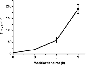
We went on to determine the long term release characteristics of the devices. The release kinetics of samples modified for 6 and 9 h were monitored up to 1200 minutes. The highest value of absorbance was reached by 6 hour samples at around 650 min and by 9 hour samples at around 1000 min. The final absorption values of solutions for all samples (modified and unmodified) are within the range of 0.185–0.205 after full release. Based on this result, we can conclude that the silica layers do not block CV from being released from the devices, it simply reduces the rate at which it can enter the solution from the microgels. To further quantify this, we determined the time it takes for each device to release 50% of total amount of loaded CV; the plot can be seen in Fig. 8. As expected, it takes devices longer to release 50% of CV when the silica layer thickness increases.
Conclusions
In this investigation, we showed that pNIPAm-co-AAc microgel-based devices coated with silica layers are very effective at controlling the release kinetics of small molecules to a system. The layers were characterized by atomic force microscopy, which showed the devices were being modified. We also showed by SIMS and XPS analysis that the amount of silica deposited on the devices was directly related to the device modification time. Finally, the release kinetics were determined, which showed that the devices released CV slower as the amount of silica on the devices increased. In the future, these silica modified devices could be used for controlled and triggered drug delivery.40,41Acknowledgements
M.J.S. acknowledges funding from the University of Alberta (the Department of Chemistry and the Faculty of Science), the Natural Sciences and Engineering Research Council of Canada (NSERC), the Canada Foundation for Innovation (CFI), the Alberta Advanced Education & Technology Small Equipment Grants Program (AET/SEGP). YG acknowledges Alberta Innovates – Technology Futures for a graduate student scholarship.References
- L. E. Bromberg and E. S. Ron, Adv. Drug Delivery Rev., 1998, 31, 197–211 CrossRef CAS
.
- E. Ayano, M. Karaki, T. Ishihara, H. Kanazawa and T. Okano, Colloids Surf., B, 2012, 99, 67–73 CrossRef CAS PubMed
.
- O. Zavgorodnya and M. J. Serpe, Colloid Polym. Sci., 2011, 289, 591–602 CAS
.
- C. D. Sorrell, M. C. Carter and M. J. Serpe, Adv. Funct. Mater., 2011, 21, 425–433 CrossRef CAS
.
- M. Karg, Y. Lu, E. Carbó-Argibay, I. Pastoriza-Santos, J. Pérez-Juste, L. M. Liz-Marzán and T. Hellweg, Langmuir, 2009, 25, 3163–3167 CrossRef CAS PubMed
.
- K. Niikura, N. Iyo, Y. Matsuo, H. Mitomo and K. Ijiro, ACS Appl. Mater. Interfaces, 2013, 5, 3900–3907 CAS
.
- Q. M. Zhang, X. Li, M. R. Islam, M. Wei and M. J. Serpe, J. Mater. Chem. C, 2014, 2, 6961–6965 RSC
.
- W. Fischer, M. A. Quadir, A. Barnard, D. K. Smith and R. Haag, Macromol. Biosci., 2011, 11, 1736–1746 CrossRef CAS PubMed
.
- B. Sahoo, K. S. P. Devi, R. Banerjee, T. K. Maiti, P. Pramanik and D. Dhara, ACS Appl. Mater. Interfaces, 2013, 5, 3884–3893 CAS
.
- I. C. Kwon, Y. H. Bae and S. W. Kim, Nature, 1991, 354, 291–293 CrossRef CAS PubMed
.
- J. Ge, E. Neofytou, T. J. Cahill III, R. E. Beygui and R. N. Zare, ACS Nano, 2012, 6, 227–233 CrossRef CAS PubMed
.
- I. I. Slowing, B. G. Trewyn, S. Giri and V. Y. Lin, Adv. Funct. Mater., 2007, 17, 1225–1236 CrossRef CAS
.
- P. Nadrah, U. Maver, A. Jemec, T. Tišler, M. Bele, G. Dražić, M. Benčina, A. Pintar, O. Planinšek and M. Gaberšček, ACS Appl. Mater. Interfaces, 2013, 5, 3908–3915 CAS
.
- L. Y. Chu, T. Yamaguchi and S.-I. Nakao, Adv. Mater., 2002, 14, 386–389 CrossRef CAS
.
- T. Hoare and R. Pelton, Langmuir, 2008, 24, 1005–1012 CrossRef CAS PubMed
.
- J. Zhang, Z.-F. Yuan, Y. Wang, W.-H. Chen, G.-F. Luo, S.-X. Cheng, R.-X. Zhuo and X.-Z. Zhang, J. Am. Chem. Soc., 2013, 135, 5068–5073 CrossRef CAS PubMed
.
- C. Wu and S. Zhou, Macromolecules, 1995, 28, 8381–8387 CrossRef CAS
.
- G. Zhang and C. Wu, J. Am. Chem. Soc., 2001, 123, 1376–1380 CrossRef CAS
.
- J. D. Debord and L. A. Lyon, Langmuir, 2003, 19, 7662–7664 CrossRef CAS
.
- T. Hoare and R. Pelton, Macromolecules, 2007, 40, 670–678 CrossRef CAS
.
- X. Ma, Y. Cui, X. Zhao, S. Zheng and X. Tang, J. Colloid Interface Sci., 2004, 276, 53–59 CrossRef CAS PubMed
.
- J. Rubio-Retama, N. E. Zafeiropoulos, C. Serafinelli, R. Rojas-Reyna, B. Voit, E. Lopez Cabarcos and M. Stamm, Langmuir, 2007, 23, 10280–10285 CrossRef CAS PubMed
.
- M. C. Carter, C. D. Sorrell and M. J. Serpe, J. Phys. Chem. B, 2011, 115, 14359–14368 CrossRef CAS PubMed
.
- Y. Gao, G. P. Zago, Z. Jia and M. J. Serpe, ACS Appl. Mater. Interfaces, 2013, 5, 9803–9808 CAS
.
- C. D. Sorrell, M. C. Carter and M. J. Serpe, ACS Appl. Mater. Interfaces, 2011, 3, 1140–1147 CAS
.
- C. D. Sorrell and M. J. Serpe, Adv. Mater., 2011, 23, 4088–4092 CrossRef CAS PubMed
.
- C. D. Sorrell and M. J. Serpe, Anal. Bioanal. Chem., 2012, 402, 2385–2393 CrossRef CAS PubMed
.
- M. R. Islam and M. J. Serpe, Macromolecules, 2013, 46, 1599–1606 CrossRef CAS
.
- M. R. Islam and M. J. Serpe, Chem. Commun., 2013, 49, 2646–2648 RSC
.
- J. B. Smiley-Wiens and M. J. Serpe, Colloid Polym. Sci., 2013, 291, 971–979 CAS
.
- L. Hu and M. J. Serpe, Polymers, 2012, 4, 134–149 CrossRef CAS PubMed
.
- M. R. Islam and M. J. Serpe, Biosens. Bioelectron., 2013, 49, 133–138 CrossRef CAS PubMed
.
- M. R. Islam and M. J. Serpe, APL Mater., 2013, 1, 052108 CrossRef PubMed
.
- M. R. Islam, Y. Gao, X. Li and M. J. Serpe, J. Mater. Chem. B, 2014, 2, 2444–2451 RSC
.
- A. Burmistrova and R. von Klitzing, J. Mater. Chem., 2010, 20, 3502–3507 RSC
.
- J. Ferguson, E. Smith, A. Weimer and S. George, J. Electrochem. Soc., 2004, 151, G528–G535 CrossRef CAS PubMed
.
- X. Deng, L. Mammen, H.-J. Butt and D. Vollmer, Science, 2012, 335, 67–70 CrossRef CAS PubMed
.
- Y. Kobayashi, H. Katakami, E. Mine, D. Nagao, M. Konno and L. M. Liz-Marzán, J. Colloid Interface Sci., 2005, 283, 392–396 CrossRef CAS PubMed
.
- D. Mitchell, K. Clark, J. Bardwell, W. Lennard, G. Massoumi and I. Mitchell, Surf. Interface Anal., 1994, 21, 44–50 CrossRef CAS
.
- C. Kneuer, M. Sameti, E. G. Haltner, T. Schiestel, H. Schirra, H. Schmidt and C.-M. Lehr, Int. J. Pharm., 2000, 196, 257–261 CrossRef CAS
.
- Y. Lu, Y. Yin, B. T. Mayers and Y. Xia, Nano Lett., 2002, 2, 183–186 CrossRef CAS
.
Footnote |
| † Authors contributed equally. |
| This journal is © The Royal Society of Chemistry 2015 |

