Shape effects of cuprous oxide particles on stability in water and photocatalytic water splitting†
Yongwoo
Kwon
a,
Aloysius
Soon
c,
Haksoo
Han
b and
Hyunjoo
Lee
*a
aDepartment of Chemical and Biomolecular Engineering, Korea Advanced Institute of Science and Technology (KAIST), Daejeon 305-701, South Korea. E-mail: azhyun@kaist.ac.kr
bDepartment of Chemical and Biomolecular Engineering, Yonsei University, Seoul 120-749, South Korea
cDepartment of Material Science and Engineering, Yonsei University, Seoul 120-749, South Korea
First published on 11th November 2014
Abstract
Cuprous oxide (Cu2O) has received much attention as a photocatalyst due to its direct band gap structure, small band gap energy, non-toxicity, and abundance. However, Cu2O usually suffers from poor stability because the oxidation state of copper is easily changed. In this work, Cu2O particles of three different shapes were prepared with distinct surface structures: cubes with (100) facets, octahedra with (111) facets, and rhombic dodecahedra with (110) facets. Their shape stability was estimated in deionized water with or without light irradiation. The Cu2O(100) facets were selectively deformed under dark conditions, as expected from density functional theory calculations. The rhombic dodecahedra showed the most violent degradation under light irradiation, with many large thorns appearing on the surface. When water splitting was attempted using the shaped Cu2O particles, the rhombic dodecahedra produced the most hydrogen, whereas the cubes produced none. Oxygen was not measured because the holes generated upon light absorption were used to oxidize the Cu2O surface to CuO. A conformal TiIrOx overlayer was successfully formed on the rhombic dodecahedral Cu2O particles, and the coated particles presented overall water splitting producing both hydrogen and oxygen. They also showed significantly improved stability over repeated water splitting reactions relative to bare Cu2O particles or TiOx-coated Cu2O particles.
Introduction
Cuprous oxide (Cu2O) has been used as a catalyst or material for CO oxidation, CO2 reduction, H2 production, gas sensing, and batteries.1–12 It is an especially promising photocatalytic material because it has a direct band gap structure, a small band gap energy (2.0–2.2 eV),13 and a high absorption coefficient over the wavelength range of the solar spectrum.14 Additionally, it is non-toxic and highly abundant.15 The shape of the catalyst nanoparticles affects their activity, selectivity, and durability significantly.16 The shape of Cu2O particles could be modulated. The surface crystalline structure (e.g., (100) facets vs. (111) facets) and the degree of branching could be controlled using electrochemical crystallization or colloidal methods.17–21 Their shape-dependent properties have been reported for photocatalytic methyl orange degradation.20,21 The band gap energy was also reported to be highly dependent on the size and shape of Cu2O particles by theoretical simulations.22Stability during the photocatalytic reaction is an important issue, but it is often neglected. Many photocatalysts suffer from poor stability under light irradiation.23 For example, CdS is one of the most widely studied photocatalysts for water splitting due to its small band gap energy and ideal band positions, but its stability is typically very poor because S is easily leached out upon photoreaction.24 When Cu2O particles are used as catalysts in aqueous solutions, Cu2O easily undergoes oxidation to CuO with degraded stability. Cu2O is often studied as a promising candidate for water splitting because the positions of the conduction and valence bands are ideal for overall water splitting. However, its poor stability in aqueous solution prevents the actual application of Cu2O for H2 production.25 The energy potential for the oxidation of Cu2O to CuO is also located above the valence band, making Cu2O oxidation more favorable than water oxidation.26,27 The facile formation of CuO on Cu2O surfaces degraded the photocatalytic activity of Cu2O materials.
Cu2O materials were deposited on electrodes, and used as a photocathode. They also suffered from poor stability, but the stability could be maintained by forming transparent and conducting overlayers such as ZnO:Al/TiO2 formed by an atomic layer deposition method.28,29 A thin TiOx layer was also used to protect the organic conducting polymer while preventing the penetration of O2 and H2O.30 However, these overlayers were applied for photoelectrochemical cells, in which electrons can pass through the protecting layer and holes can be dumped into the external circuit. When colloidal particle photocatalysts are used, both electrons and holes must be able to pass through the protecting overlayers.
In this work, we prepared colloidal Cu2O particles of different shapes: cubes with (100) facets, octahedra with (111) facets, and rhombic dodecahedra with (110) facets. Their stability was tested in deionized water with or without light irradiation. The trend in stability over different shapes was confirmed by density functional theory (DFT) calculations. The Cu2O particles were used as photocatalysts for overall water splitting, and the shape-dependence on the stability and H2 production was investigated. The Cu2O particles were coated with a TiIrOx overlayer to enhance their stability and suppress photocorrosion. The TiIrOx film effectively consumed electrons and holes separately in a stable manner.
Experimental
Materials
Copper(II) sulfate pentahydrate (CuSO4·5H2O, 98%), copper(II) chloride dihydrate (CuCl2·2H2O, 98%), sodium hydroxide (NaOH, 97%), oleic acid (99%), iridium(III) chloride hydrate (IrCl3·xH2O, 99.9%), D-(+)-glucose (99%), L-ascorbic acid (99%), titanium butoxide (TBOT, 97%), and anhydrous ethanol (EtOH, 99.5%) were purchased from Sigma Aldrich. Deionized water (18.3 MΩ cm) was purified by Human Power II+ Scholar (Human Corporation).Synthesis of shape-controlled cuprous oxide
Cu2O cubes were synthesized by a previously reported method.31 1 mmol of CuCl2·2H2O was dissolved in 100 ml of H2O. Next, 10 ml of 2 M NaOH solution was added to the solution under vigorous stirring. After 30 min, 10 ml of 6 M L-ascorbic acid was injected and stirred for additional 3 h. All processes were performed at 55 °C. Cu2O octahedra and rhombic dodecahedra were synthesized by a previously reported method.32 1 mmol of CuSO4·5H2O was dissolved in 40 ml of H2O. 3 ml or 6 ml of oleic acid dissolved in 20 ml of ethanol was added under vigorous stirring to obtain octahedra or rhombic dodecahedra, respectively. After the solution was heated to 100 °C, 10 ml of 0.8 M NaOH aqueous solution was injected, and the mixture was held at this temperature for 5 min. 3.42 g of D-(+)-glucose was dissolved in 30 ml of water and added to the above solution, which was then stirred for 3 h. The final solution was washed with isopropyl alcohol and ethanol and collected by centrifugation. The collected particles were dried at 50 °C for 3 h under vacuum. The stability in pure water was investigated by dispersing the Cu2O particles in deionized water without purging in a ratio of 1 mg Cu2O per 1 ml water under dark conditions for 3 weeks or with light irradiation with a 300 W Xe lamp for 9 h.Coating shape-controlled cuprous oxides with TiIrOx overlayers
33 mg of Cu2O particles were dispersed in 5.4 ml of anhydrous EtOH. 3.8 mg of IrCl3·xH2O was dissolved in 5 ml of anhydrous EtOH and 168 μl of water was added to the above solution. 45 μl of TBOT was added into 5 ml of cold anhydrous EtOH. Three solutions kept at 0 °C were mixed under vigorous stirring and kept at the same temperature for 1 h. The reddish precipitates were then washed with water and ethanol several times and dried in a vacuum oven at 50 °C. The powder was heated at 210 °C for 2 h under nitrogen.Hydrogen generation by water splitting
The reactor consisted of a 100 ml round-bottom flask with a quartz plate window and a Teflon cover with two tubes connected to a gas chromatograph (GC) and an Ar cylinder. 100 mg of each sample was dispersed in 100 ml of pure water without sacrificial agents. After Ar purging for ∼20 min (until no nitrogen peak was detected by GC), irradiation was applied for 24 h. The light source was a 300 W Xe lamp, and the distance from the light source to the reactor was 20 cm. A 1 cm thick water bath was located between the light source and the reactor. After the reaction, 25 ml of Ar was injected into the reactor, and the outlet products were analyzed by using a GC (Younglin GC 6000 series) equipped with a thermal conductivity detector.Characterization
The morphology of the samples was investigated by field emission scanning electron microscopy (FE-SEM; JEOL6701, 5 kV) and transmission electron microscopy (TEM; JEOL2100). The X-ray powder diffraction (XRD) patterns of the prepared samples were measured on a Rigaku Miniflex diffractometer. An X-ray photoelectron spectrometer (XPS; K-alpha, Thermo U. K.) equipped with a monochromatic Al Kα X-ray source (12 kV, 3 mA) was used to measure the surface properties of the nanoparticles. Binding energies were calculated using the maximum intensity of the C 1s signal at 284.8 eV as a reference.Results and discussion
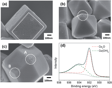
Cu2O particles of three shapes with well-defined surfaces were synthesized using the reported methods. The cubes exclusively feature (100) facets, the octahedra (111) facets, and the rhombic dodecahedra (110) facets. The SEM images of each type of particle are shown in Fig. 1(a)–(c). Fig. 1(d) shows the XPS Cu 2p3/2 peak of the rhombic dodecahedral Cu2O particles. Only the Cu(I) peak was observed, not the peak related to Cu(II), indicating that the surface consists of only Cu2O. From Fig. 1(d) and S1(a and d),† all of the particle surfaces are Cu2O, no other phase such as CuO was present. The Cu2O crystalline structure was also confirmed by XRD (Fig. S2(a)†). The shaped Cu2O particles were dispersed in deionized water under dark conditions to assess the stability of the particles in water. After 3 weeks, the surface of the Cu2O particles was degraded, and the extent of surface degradation differed by the particle shape. The SEM images of each Cu2O shape in water are shown in Fig. 2(a)–(c). In the case of cubic Cu2O, the faces were deformed, with many bumps on the facet, while the edges and vertices showed no change. In the octahedral particles, the facets were stable, but all vertices were degraded, as shown by the circled areas in Fig. 2(b). In the rhombic dodecahedra, the facets were stable, but the vertices showed deformation. Here, interestingly, the vertices where four facets met were degraded as shown in circle A in Fig. 2(c), but the vertices where three facets met showed no degradation as shown in circle B. All these observations indicate that only (100) facets were degraded when Cu2O particles were in contact with water. The XPS data in Fig. 2(d) and S1(b and e)† showed that the Cu2O surfaces were oxidized after dispersion in water. Compared with XPS O 1s data in Fig. S3,† the oxidized Cu would have a form of Cu(OH)2. The ratio of Cu(II) to Cu(I) was estimated by integrating the deconvoluted peaks. The ratio was 1.42 for cubes, 0.68 for octahedra, and 0.74 for rhombic dodecahedra. The cubes have the highest ratio of Cu(II) among different shapes, thus the surface of the cubic Cu2O crystals was the most unstable in deionized water. However, the crystalline structure was still found to be Cu2O in the XRD patterns (Fig. S2(b)†), and no other peaks were observed in any of the samples.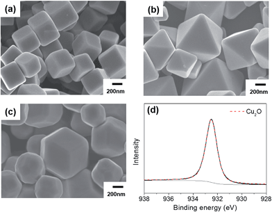 | ||
| Fig. 1 SEM images of the as-made (a) cubic, (b) octahedral, and (c) rhombic dodecahedral Cu2O. (d) XPS Cu 2p3/2 peak for the as-made rhombic dodecahedral Cu2O. | ||
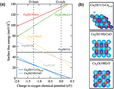
The relative thermodynamic stability of the Cu2O surfaces has been analyzed using first principles density functional theory (DFT).33,34 The calculation details can be found in ref. 33 and 34. The surface energy was defined with respect to bulk stoichiometric Cu2O. Any surface structure or surface composition that deviates from Cu![[thin space (1/6-em)]](https://www.rsc.org/images/entities/char_2009.gif) :
:![[thin space (1/6-em)]](https://www.rsc.org/images/entities/char_2009.gif) O = 2
O = 2![[thin space (1/6-em)]](https://www.rsc.org/images/entities/char_2009.gif) :
:![[thin space (1/6-em)]](https://www.rsc.org/images/entities/char_2009.gif) 1 will have a slope. Using the approach of DFT-based atomistic thermodynamics, both low and high Miller-index surfaces of Cu2O were studied, and their surface free energies are plotted as a function of oxygen chemical potential in Fig. 3(a). Two low Miller-index Cu2O surfaces, i.e., the Cu–O terminated Cu2O(110) surface [Cu2O(110):CuO] and the Cu2O(111) surface with a surface Cu vacancy [Cu2O(111)–CuCUS], show the lowest surface free energies, which means that they are the most thermodynamically stable within the considered range of oxygen chemical potential. In Cu2O(110):CuO, the surface has both Cu and O in the same atomic level. The detailed atomic structures of the most stable form of each surface are shown in Fig. 3(b). The vertical dashed lines in Fig. 3(a) indicate the physical limits of the oxygen chemical potentials. If the oxygen chemical potential drops below the left line, bulk Cu2O will break down to form bulk Cu. Thus, the left area can be considered to be an oxygen-poor condition. The right line indicates the maximum value of the oxygen chemical potential, which is the thermodynamic ground state: dioxygen molecules. Thus, the right area is an oxygen-rich condition. From this thermodynamic analysis, it is clearly shown that both O- and Cu-terminated (100) surfaces of Cu2O are relatively unstable under oxygen-containing conditions.
1 will have a slope. Using the approach of DFT-based atomistic thermodynamics, both low and high Miller-index surfaces of Cu2O were studied, and their surface free energies are plotted as a function of oxygen chemical potential in Fig. 3(a). Two low Miller-index Cu2O surfaces, i.e., the Cu–O terminated Cu2O(110) surface [Cu2O(110):CuO] and the Cu2O(111) surface with a surface Cu vacancy [Cu2O(111)–CuCUS], show the lowest surface free energies, which means that they are the most thermodynamically stable within the considered range of oxygen chemical potential. In Cu2O(110):CuO, the surface has both Cu and O in the same atomic level. The detailed atomic structures of the most stable form of each surface are shown in Fig. 3(b). The vertical dashed lines in Fig. 3(a) indicate the physical limits of the oxygen chemical potentials. If the oxygen chemical potential drops below the left line, bulk Cu2O will break down to form bulk Cu. Thus, the left area can be considered to be an oxygen-poor condition. The right line indicates the maximum value of the oxygen chemical potential, which is the thermodynamic ground state: dioxygen molecules. Thus, the right area is an oxygen-rich condition. From this thermodynamic analysis, it is clearly shown that both O- and Cu-terminated (100) surfaces of Cu2O are relatively unstable under oxygen-containing conditions.
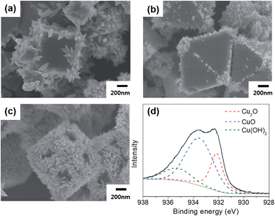
The stabilities of the shaped Cu2O particles were also examined under light irradiation for 9 h. The Cu2O particles were dispersed in deionized water and illuminated by a 300 W Xe lamp. All the shaped Cu2O particles presented photocorrosion at the surface, but the degree of corrosion differed by the particle shape. Fig. 4 shows the SEM images of Cu2O particles after irradiation. Many thorns were observed, especially at the edges. The density and the size of the thorns were the smallest for octahedra and largest for rhombic dodecahedra. This trend was also confirmed by XPS. The peak area ratio of Cu(II) to Cu(I) was 0.60 for the cubes, 0.50 for the octahedra, and 2.67 for the rhombic dodecahedra. The surface of the octahedra, which have the smallest ratio of Cu(II) by XPS, was degraded the least, and the surface of the rhombic dodecahedra, which have the highest ratio of Cu(II), was deformed the most. The formation of a CuO phase was also observed in the XRD pattern (Fig. S2(c)†). Clearly, the stability trend under light irradiation was different from that under dark conditions. The formation of electrons and holes upon light absorption affects the stability differently. Zheng et al. previously reported that Cu2O(111) was more stable than the other surface structures and acted as a stable photocatalyst for methyl orange degradation under irradiation.35 From density of states calculations, they showed that the valence band of Cu2O(100) and Cu2O(110) extends to higher energies compared to Cu2O(111), causing electrons to tend to move to the (111) surface from other surfaces.35
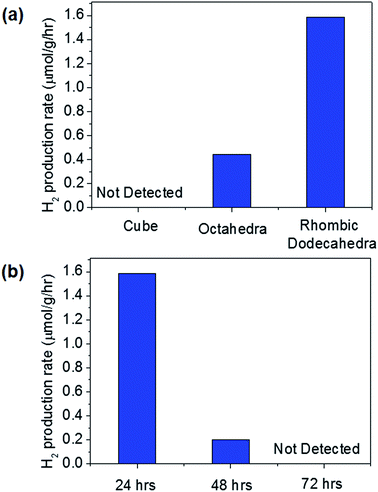
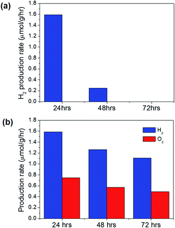
Upon light absorption, Cu2O can act as a water-splitting photocatalyst. Hydrogen production was measured for each sample after dispersing 0.1 g of the catalyst in 100 ml of water after Ar purging under light irradiation with a 300 W Xe lamp for 24 h. No sacrificial agent was used, and overall water splitting was expected, producing hydrogen and oxygen in a 2![[thin space (1/6-em)]](https://www.rsc.org/images/entities/char_2009.gif) :
:![[thin space (1/6-em)]](https://www.rsc.org/images/entities/char_2009.gif) 1 ratio. When the Cu2O particles of different shapes were used for photocatalytic water splitting, the H2 production rates were obtained as shown in Fig. 5(a). No oxygen was detected because the holes that were supposed to oxidize water to produce oxygen were actually used to oxidize Cu2O to CuO. The thorns shown in Fig. 4 are CuO oxidized by holes formed after light absorption. A strong shape dependence was observed for H2 production. The Cu2O cubes produced no hydrogen, and the Cu2O rhombic dodecahedra generated the most hydrogen. Many thorns on the rhombic dodecahedra as shown in Fig. 4(c) indicate the high activity of this shape for photocatalytic reactions. Huang et al. also reported much better catalytic activity of rhombic dodecahedra than cubes for methyl orange degradation.15 However, when the water splitting was repeated for rhombic dodecahedra, the activity dropped significantly, and no H2 was detected for the third run, as shown in Fig. 5(b). This degradation in photocatalytic activity is due to the photocorrosion of Cu2O into CuO during water splitting. If the photocorrosion can be suppressed, stable H2 production might be achieved.
1 ratio. When the Cu2O particles of different shapes were used for photocatalytic water splitting, the H2 production rates were obtained as shown in Fig. 5(a). No oxygen was detected because the holes that were supposed to oxidize water to produce oxygen were actually used to oxidize Cu2O to CuO. The thorns shown in Fig. 4 are CuO oxidized by holes formed after light absorption. A strong shape dependence was observed for H2 production. The Cu2O cubes produced no hydrogen, and the Cu2O rhombic dodecahedra generated the most hydrogen. Many thorns on the rhombic dodecahedra as shown in Fig. 4(c) indicate the high activity of this shape for photocatalytic reactions. Huang et al. also reported much better catalytic activity of rhombic dodecahedra than cubes for methyl orange degradation.15 However, when the water splitting was repeated for rhombic dodecahedra, the activity dropped significantly, and no H2 was detected for the third run, as shown in Fig. 5(b). This degradation in photocatalytic activity is due to the photocorrosion of Cu2O into CuO during water splitting. If the photocorrosion can be suppressed, stable H2 production might be achieved.
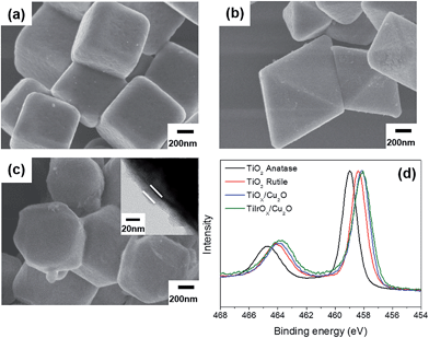
Coating the Cu2O particles would prevent direct contact between the Cu2O surface and water. TiOx (x < 2) has been widely studied as a conducting and transparent overlayer and has also been found to be effective in protecting Cu2O electrode materials when used together with a ZnO layer.28,29 However, Cu2O was deposited on the electrode in these works, and atomic layer deposition was used to form ultrathin and conformal TiOx overlayers. This method cannot be applied to powder-type Cu2O particles. Instead, we used a sol–gel method to coat the Cu2O particles and treated TiOx-coated samples at different temperatures. When the heating temperature was 240 °C, the CuO phase started to form as shown in Fig. S4(a).† When temperatures of 150, 180, and 210 °C were used to form the TiOx layer and the coated particles were exposed to light, 210 °C showed the least formation of CuO; thus, thermal treatment at 210 °C was chosen to preserve the Cu2O phase. It was confirmed that the formation of thorns was greatly reduced upon light irradiation for TiOx-coated Cu2O particles. However, the TiOx layer was not enough to guarantee stable water splitting. Although electrons can pass through the TiOx overlayer and generate H2, holes would accumulate inside the particles, prohibiting further photocatalytic reactions. Therefore, IrOx, an effective water oxidation catalyst,36 was also inserted into the overlayer. When Ir precursors were added into the sol solution, a TiIrOx overlayer was successfully formed, as shown in Fig. 6. All the shapes could be coated conformably, and the coating layer has a thickness of ∼20 nm. When the binding energy of Ti 2p peaks was observed as shown in Fig. 6(d), the TiOx layer on Cu2O particles presented a lower binding energy than TiO2 rutile or anatase, indicating an abundance of electrons on the TiOx layer. The addition of Ir produced little change in the electronic state of Ti. The SEM images in Fig. 6 rarely showed distinguishable separate particles in the overlayer although the rough layer in the TEM image (inset of Fig. 6(c)) may reflect the co-existence of the TiOx layer and IrOx particles. The XPS Ir 4f peaks in Fig. S5† presented Ir(IV) peaks only, indicating that most Ir existed as IrO2 and that few Ir precursors remained.
The overall water splitting performance of the coated particles was tested as shown in Fig. 7. As expected, the TiOx layer did not enhance the stability; H2 production stopped at the third run. For the TiIrOx layer, however, overall water splitting was obtained with a H2![[thin space (1/6-em)]](https://www.rsc.org/images/entities/char_2009.gif) :
:![[thin space (1/6-em)]](https://www.rsc.org/images/entities/char_2009.gif) O2 ratio of 2.13 for the first run as shown in Fig. 7(b). Bare rhombic dodecahedral Cu2O, TiOx-coated particles, and TiIrOx-coated particles showed similar hydrogen production rates for the first run, implying that electron transfer at the bare Cu2O surface differed little from that through the overlayers. IrOx at the overlayers facilitated hole transfer, preventing photocorrosion and thereby enabling water oxidation producing oxygen. Under dark conditions, there was no hydrogen production. To ensure further that the overall water splitting is not from ‘mechano-catalysis’,37–41 a round-bottom flask and an egg shaped stirring bar were used to minimize the contact area. When TiIrOx was synthesized without Cu2O particles under otherwise the same synthesis conditions, hydrogen was not detected in the outlet under light irradiation. The stability was also checked by repeating the water splitting after collecting the coated particles and redispersing them in Ar-purged deionized water. The water splitting was observed to produce both hydrogen and oxygen, but the production rates decreased slightly. The ratio of hydrogen to oxygen increased from 2.13 for the first run to 2.20 for the second run and to 2.26 for the third run. The TiIrOx overlayer enabled both electron and hole transfer, suppressing photocorrosion and significantly improving the stability. However, the coating might not completely prevent contact with water, allowing a small proportion of the holes to be used for surface oxidation with degraded hydrogen/oxygen production. When the coated particles were observed by SEM after the third cycle of photocatalytic water splitting, the shape and coating were mostly preserved in contrast to Fig. 4(c), and few thorns were observed (Fig. S6†).
O2 ratio of 2.13 for the first run as shown in Fig. 7(b). Bare rhombic dodecahedral Cu2O, TiOx-coated particles, and TiIrOx-coated particles showed similar hydrogen production rates for the first run, implying that electron transfer at the bare Cu2O surface differed little from that through the overlayers. IrOx at the overlayers facilitated hole transfer, preventing photocorrosion and thereby enabling water oxidation producing oxygen. Under dark conditions, there was no hydrogen production. To ensure further that the overall water splitting is not from ‘mechano-catalysis’,37–41 a round-bottom flask and an egg shaped stirring bar were used to minimize the contact area. When TiIrOx was synthesized without Cu2O particles under otherwise the same synthesis conditions, hydrogen was not detected in the outlet under light irradiation. The stability was also checked by repeating the water splitting after collecting the coated particles and redispersing them in Ar-purged deionized water. The water splitting was observed to produce both hydrogen and oxygen, but the production rates decreased slightly. The ratio of hydrogen to oxygen increased from 2.13 for the first run to 2.20 for the second run and to 2.26 for the third run. The TiIrOx overlayer enabled both electron and hole transfer, suppressing photocorrosion and significantly improving the stability. However, the coating might not completely prevent contact with water, allowing a small proportion of the holes to be used for surface oxidation with degraded hydrogen/oxygen production. When the coated particles were observed by SEM after the third cycle of photocatalytic water splitting, the shape and coating were mostly preserved in contrast to Fig. 4(c), and few thorns were observed (Fig. S6†).
Conclusions
Cu2O particles of three different shapes (cubes, octahedra, and rhombic dodecahedra) were prepared with distinct surface structures ((100), (111), and (110) facets, respectively). Their shape stability was estimated in deionized water. The facets of the cubes, the vortexes of the octahedra, and certain vortexes of the rhombic dodecahedra were degraded, with rough surfaces. The Cu2O(100) facets were selectively deformed when dispersed in deionized water, consistent with density functional theory results. When the shaped Cu2O particles were exposed to light, a tendency of more violent deformation at the edges was observed. Upon light irradiation, the generated holes were used to oxidize Cu2O to CuO; the smooth Cu2O surface was deformed into a thorny CuO surface. When the overall water splitting was performed using Cu2O particles as photocatalysts, a shape dependence was observed; no hydrogen was obtained for the cubes, whereas most hydrogen was produced by the rhombic dodecahedra. Oxygen was not produced because the holes were used to form CuO, and this was the reason that Cu2O had poor stability. When the rhombic dodecahedral Cu2O particles were coated with a conformal TiIrOx layer, overall water splitting producing both hydrogen and oxygen was observed. Bare Cu2O particles or TiOx-coated Cu2O particles showed a sudden decrease in photocatalytic activity over repeated reactions due to severe photocorrosion. In contrast, TiIrOx-coated Cu2O particles presented significantly enhanced stability for the overall water splitting reaction.Acknowledgements
This work was supported by the Global Frontier R&D Program on Center for Multiscale Energy System (2011-0031575) through the National Research Foundation of Korea funded by the Ministry of Education, Science and Technology, and KAIST HRHR program.Notes and references
- H. Z. Bao, W. H. Zhang, Q. Hua, Z. Q. Jiang, J. L. Yang and W. X. Huang, Angew. Chem., Int. Ed., 2011, 50, 12294 CrossRef CAS PubMed.
- D. Barreca, G. Carraro, V. Gombac, A. Gasparotto, C. Maccato, P. Fornasiero and E. Tondello, Adv. Funct. Mater., 2011, 21, 2611 CrossRef CAS.
- J. N. Nian, C. C. Hu and H. Teng, Int. J. Hydrogen Energy, 2008, 33, 2897 CrossRef CAS PubMed.
- S. Kakuta and T. Abe, ACS Appl. Mater. Interfaces, 2009, 1, 2707 CAS.
- D. Barreca, P. Fornasiero, A. Gasparotto, V. Gombac, C. Maccato, T. Montini and E. Tondello, ChemSusChem, 2009, 2, 230 CrossRef CAS PubMed.
- G. Ghadimkhani, N. R. de Tacconi, W. Chanmanee, C. Janaky and K. Rajeshwar, Chem. Commun., 2013, 49, 1297 RSC.
- D. Barreca, G. Carraro, E. Comini, A. Gasparotto, C. Maccato, C. Sada, G. Sberveglieri and E. Tondello, J. Phys. Chem. C, 2011, 115, 10510 CAS.
- D. Barreca, G. Carraro, A. Gasparotto, C. Maccato, M. Cruz-Yusta, J. L. Gomez-Camer, J. Morales, C. Sada and L. Sanchez, ACS Appl. Mater. Interfaces, 2012, 4, 3610 CAS.
- D. Barreca, G. Carraro, A. Gasparotto, C. Maccato, O. I. Lebedev, A. Parfenova, S. Turner, E. Tondello and G. Van Tendeloo, Langmuir, 2011, 27, 6409 CrossRef CAS PubMed.
- J. Kim, Y. Kwon and H. Lee, J. Mater. Chem. A, 2013, 1, 14183 CAS.
- V. Gombac, L. Sordelli, T. Montini, J. J. Delgado, A. Adamski, G. Adami, M. Cargnello, S. Bernal and P. Fornasiero, J. Phys. Chem. A, 2010, 114, 3916 CrossRef CAS PubMed.
- L. Pan, J. J. Zou, T. R. Zhang, S. B. Wang, Z. Li, L. Wang and X. W. Zhang, J. Phys. Chem. C, 2014, 118, 16335 CAS.
- X. L. Nie, S. H. Wei and S. B. Zhang, Phys. Rev. B: Condens. Matter Mater. Phys., 2002, 65, 075111 CrossRef.
- P. E. de Jongh, D. Vanmaekelbergh and J. J. Kelly, J. Electrochem. Soc., 2000, 147, 486 CrossRef CAS PubMed.
- M. Hara, T. Kondo, M. Komoda, S. Ikeda, K. Shinohara, A. Tanaka, J. N. Kondo and K. Domen, Chem. Commun., 1998, 357 RSC.
- H. Lee, RSC Adv., 2014, 4, 41017 RSC.
- K. S. Choi, J. Phys. Chem. Lett., 2010, 1, 2244 CrossRef CAS.
- M. J. Siegfried and K. S. Choi, Adv. Mater., 2004, 16, 1743 CrossRef CAS.
- M. J. Siegfried and K. S. Choi, Angew. Chem., Int. Ed., 2005, 44, 3218 CrossRef CAS PubMed.
- J. Y. Ho and M. H. Huang, J. Phys. Chem. C, 2009, 113, 14159 CAS.
- W. C. Huang, L. M. Lyu, Y. C. Yang and M. H. Huang, J. Am. Chem. Soc., 2012, 134, 1261 CrossRef CAS PubMed.
- B. Sinha, T. Goswami, S. Paul and A. Misra, RSC Adv., 2014, 4, 5092 RSC.
- A. Kudo and Y. Miseki, Chem. Soc. Rev., 2009, 38, 253 RSC.
- H. Matsumoto, T. Sakata, H. Mori and H. Yoneyama, J. Phys. Chem., 1996, 100, 13781 CrossRef CAS.
- S. Kakuta and T. Abe, Electrochem. Solid-State Lett., 2009, 12, P1 CrossRef CAS PubMed.
- L. I. Bendavid and E. A. Carter, J. Phys. Chem. B, 2013, 117, 15750 CrossRef CAS PubMed.
- P. E. de Jongh, D. Vanmaekelbergh and J. J. Kelly, Chem. Commun., 1999, 1069 RSC.
- A. Paracchino, V. Laporte, K. Sivula, M. Gratzel and E. Thimsen, Nat. Mater., 2011, 10, 456 CrossRef CAS PubMed.
- A. Paracchino, N. Mathews, T. Hisatomi, M. Stefik, S. D. Tilley and M. Gratzel, Energy Environ. Sci., 2012, 5, 8673 CAS.
- S. Cho, K. Lee and A. J. Heeger, Adv. Mater., 2009, 21, 1941 CrossRef CAS.
- D. F. Zhang, H. Zhang, L. Guo, K. Zheng, X. D. Han and Z. Zhang, J. Mater. Chem., 2009, 19, 5220 RSC.
- X. D. Liang, L. Gao, S. W. Yang and J. Sun, Adv. Mater., 2009, 21, 2068 CrossRef CAS.
- A. Soon, X. Y. Cui, B. Delley, S. H. Wei and C. Stampfl, Phys. Rev. B: Condens. Matter Mater. Phys., 2009, 79, 035205 CrossRef.
- A. Soon, M. Todorova, B. Delley and C. Stampfl, Phys. Rev. B: Condens. Matter Mater. Phys., 2007, 75, 125420 CrossRef.
- Z. K. Zheng, B. B. Huang, Z. Y. Wang, M. Guo, X. Y. Qin, X. Y. Zhang, P. Wang and Y. Dai, J. Phys. Chem. C, 2009, 113, 14448 CAS.
- B. H. Meekins and P. V. Kamat, J. Phys. Chem. Lett., 2011, 2, 2304 CrossRef CAS.
- K. Domen, S. Ikeda, T. Takata, A. Tanaka, M. Hara and J. N. Kondo, Appl. Energy, 2000, 67, 159 CrossRef CAS.
- M. Hara, H. Hasei, M. Yashima, S. Ikeda, T. Takata, J. N. Kondo and K. Domen, Appl. Catal., A, 2000, 190, 35 CrossRef CAS.
- S. Ikeda, T. Takata, T. Kondo, G. Hitoki, M. Hara, J. N. Kondo, K. Domen, H. Hosono, H. Kawazoe and A. Tanaka, Chem. Commun., 1998, 2185 RSC.
- S. Ikeda, T. Takata, M. Komoda, M. Hara, J. N. Kondo, K. Domen, A. Tanaka, H. Hosono and H. Kawazoe, Phys. Chem. Chem. Phys., 1999, 1, 4485 RSC.
- M. Hara, M. Komoda, H. Hasei, M. Yashima, S. Ikeda, T. Takata, J. N. Kondo and K. Domen, J. Phys. Chem. B, 2000, 104, 780 CrossRef CAS.
Footnote |
| † Electronic supplementary information (ESI) available: XPS data of the as-made and treated particles, XRD patterns of the as-made and treated particles, XRD patterns of heat-treated TiOx-coated particles, XPS data of the TiIrOx overlayer, and the SEM image of TiIrOx-coated Cu2O after the reaction. See DOI: 10.1039/c4ta04863f |
| This journal is © The Royal Society of Chemistry 2015 |

