Superhigh-speed unidirectional rotation of a carbon nanotube in a sheared fluid and its decoupled dynamics

Ruo-Yu Dong and Bing-Yang Cao*
Key Laboratory for Thermal Science and Power Engineering of Ministry of Education, Department of Engineering Mechanics, Tsinghua University, Beijing 100084, P. R. China. E-mail: caoby@tsinghua.edu.cn; Fax: +86-10-6279-4531; Tel: +86-10-6279-4531

Received 15th September 2015 , Accepted 14th October 2015

First published on 14th October 2015


Abstract

The superhigh-speed unidirectional rotation of a carbon nanotube (CNT) induced by a linear shear flow is investigated by molecular dynamics simulations. We have identified three rotational types: “continuous rotation”, “interrupted rotation” and “simple oscillation”, corresponding to a decreased number of unidirectional rotation circles over the same time duration. It was found that the unidirectional motion and oscillation respectively originate from the applied shear and rotary Brownian motion by a decoupled analysis of the rotational features. The angular velocity of the unidirectional motion is over one order of magnitude larger than the Jeffery's theory. To construct a CNT-based rotary motor with good performance, the high-speed unidirectional angular velocity can be achieved by carefully selecting the shear rate (e.g. ∼2 × 10⁸ rad s−1 at 35 GHz) and the continuous rotating state can be approached by using a low aspect ratio carbon nanotube.
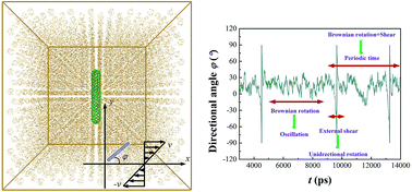

1. Introduction

Nanomachine engineering has attracted intense research interest, among which is the desire to construct delicate rotary nanomotors. In biological systems, the typical study subjects of molecular motors include F0F1-ATPase1 and flagella,2 which can convert chemical energy to mechanical movements and serve as functional parts in many natural-synthetic hybrid systems.3,4 These natural or semi-natural motors suffer from restrictions of the environmental conditions,5 and the demands of wholly artificial nano-systems6–9 have accordingly arisen. Thus, researchers have witnessed a variety of studies utilizing magnetic field,10 electric field11,12 or polarized light13 to realize unidirectional rotation of nanoparticles, and the applications are extended from biological issues to micro/nanofluidics and micro/nanoelectromechanical systems (MEMS/NEMS). Carbon nanotube (CNT) based motors are the current focus, due to CNT's great mechanical and electronic properties as well as its biocompatibility14 and near-infrared fluorescent features,15 all of which make CNTs a suitable component for the above listed areas. For instance, one of these topics is the double-walled CNT rotating systems composed of a stator and a rotor without liquid media.16,17

When CNTs are dispersed in suspensions, an easy way to control its rotational motion is by imposing a fluid flow. Studies on this issue were mostly focusing on the orientation state18,19 and related rheological phenomena20 of CNT suspensions. However, the related motor study is scarce, only recently a nano-turbine model consisted of a CNT and three graphene blades was designed to rotate unidirectionally in water flow by molecular dynamics (MD) simulations.21 Some light was shed on this problem by Jeffrey22 in 1922 who theoretically predicted that a single ellipsoid would rotate unidirectionally in a single parameter family of closed orbits in a sheared viscous fluid. Later studies extended the Jeffery orbits to rod-shaped particles,23 just like CNT, and considered the influences of rotary Brownian motion.24,25 The MD results25 confirmed that the rotation period of a low aspect ratio CNT in linear shear agrees with Jeffery's theory with only a slight difference. The flow-induced nanoparticle rotation is actually a coupled effect from the applied shear and Brownian rotation, whose impacts have not been distinguished from each other previously. This study thus provides detailed analyses on a single CNT's two-dimensional (2D) rotational behavior and dynamics as well as the decoupled features and their origin by MD simulations. The simulated very small aspect ratio CNT is treated as a rigid rod19,25 without considering the effect of deformation.26,27 The high-speed unidirectional rotation is observed and the criteria to achieve it are discussed to better facilitate the CNT-based rotary motor design.

2. Simulation methods

Fig. 1(a) exhibits a capped CNT embedded in fluid argon for the MD simulations, which were performed by the MD package LAMMPS.28 The forces between the argon atoms and between the argon and carbon atoms were calculated based on the Lennard-Jones (LJ) pair potential image file: c5ra18901b-t1.tif. The basic parameters are σAr–Ar = 0.341 nm, εAr–Ar = 1.67 × 10⁻²¹ J, σC–Ar = 0.357 nm, and εC–Ar = 1.97 × 10⁻²¹ J.29,30 The C–C interactions were not considered since the CNT was assumed to be a rigid body,25 so a larger time step of 10 fs could be used in the calculations. The time-consuming calculations of the inter-particle interactions were reduced by using a cutoff distance of 0.77 nm.25,29 The NVT canonical ensemble was used with the Nose–Hoover thermostat.
image file: c5ra18901b-f1.tif
Fig. 1 (a) Schematic diagram of the initial configuration of the MD simulation system; (b) schematic viewing of the applied linear shear in the orthogonal coordinates. The inset inside a dashed rectangle defines the range of CNT's directional angle φ.

The superimposed simple linear shear flow is illustrated in Fig. 1(b) and in the form of vx = [small gamma, Greek, dot above]y, vy = vz = 0, where [small gamma, Greek, dot above] stands for the shear rate. It was realized by utilizing the SLLOD algorithm.31 The Lee–Edwards boundary condition32 was applied in the y direction, which is the velocity gradient direction with periodic boundary conditions for the other two directions. The excess heat produced by the shear flow was extracted by the thermostat. The thermostat was only applied in two directions (y, z) and not in the flow direction (x).19,33,34 The results were collected after 3 × 10⁵ time steps (3000 ps) to allow time for the flow to develop.

The CNT is confined only to rotate two-dimensionally (2D) on the xy plane.35 Also shown in Fig. 1(b) is the definition of the CNT's directional angle φ, which is within a range of (−90°, 90°] and φ = 0° means the CNT axis is parallel to the flow direction x. To model a rod-shaped object, the CNT was treated as a rigid body. The base case is defined here: the nanotube has the armchair (5, 5) configuration with a diameter, d, of 0.7 nm and length, L, of 4.4 nm. The density, ρ, of the argon is 1091 kg m−3 and the temperature, T, is 300 K and the shear rate, [small gamma, Greek, dot above], is 20.0 GHz. The simulated argon system is in a supercritical state. Later analyses will alter various factors based on the above selected state.

3. Results and discussion

Three types of rotational behavior appear for the time-varying angle, φ, as shown in Fig. 2(a)–(c). The CNT in Fig. 2(a), which has the same state parameters as the base case except for L = 0.9 nm, rotates continuously all the time in a clockwise direction, agreeing with the form of the imposed shear in Fig. 1(b). Back-and-force oscillations can be observed in infinitesimal time periods, but the motion is dominated by the unidirectional rotations, one of which is shown in Fig. 2(d). A discontinuous jump exists at −90° to 90° due to the angle definition. While in Fig. 2(b) (the base case), only a few unidirectional rotation periods can be observed and they are interrupted by back-and-force oscillations greatly. No clockwise rotation exists in Fig. 2(c), where the CNT always oscillates around a particular angle when the shear rate [small gamma, Greek, dot above] = 50.0 GHz. The above three rotational types are classified as “continuous rotation”, “interrupted rotation” and “simple oscillation”, respectively, similar to the three orientation types found in our previous three-dimensional rotation study.19 Considering the potential usage on a CNT-based rotary motor, the continuous rotation state should be paid more attention.
image file: c5ra18901b-f2.tif
Fig. 2 The time-varying angle φ displays three types of rotational behavior: (a) continuous rotation, (b) interrupted rotation and (c) simple oscillation. The labels “1”, “2” and “3” in (b) respectively indicate the oscillatory motion, two successive unidirectional rotations and the oscillation in between, and the unidirectional rotation. The state parameters are the same as those in the base case, except for (a) CNT length L = 0.9 nm, (c) shear rate [small gamma, Greek, dot above] = 50 GHz. (d) is an example of the unidirectional rotation, picked out from (a).

Next, the rotational modes will be decoupled to explore their physical origin as well as to better comprehend and control the above three rotational types. Shown in Fig. 2(b), the labels “1”, “2” and “3” indicate the distinctive segments of the CNT's rotational motion, about to be analyzed one by one in the following discussion. Label “1”: the oscillatory motion between two successive unidirectional rotations. The strength of the oscillation is characterized by the time-averaged frequency f. Label “2”: the total time period Tp of two successive unidirectional rotations and the oscillation in between. The simulation time is prolonged to ensure there are at least 10 individual sets of Tp to achieve its reliable average value. Label “3”: the unidirectional rotation, which is the focus of the present study. We use the angular velocity ω to characterize the unidirectional rotation speed, which was also averaged over 10 individual unidirectional rotations appearing with time. It should be noticed that the boundary between rotation and oscillation is not distinct and there exists a preferred orientation angle around +10° where the CNT oscillates around (Fig. 2(b)). Therefore, the intermediate total rotation angles of 120°, corresponding to the CNT orientation from −30° to 30° (refer to Fig. 2(d)), is used to measure the unidirectional angular velocity ω. As the simple oscillatory state does not exhibit any unidirectional motion (Fig. 2(a)), labels “2” and “3” will not be discussed at that circumstance.

Fig. 3(a) & (b) show the time-averaged oscillatory frequency f (label “1”) versus the rotational diffusion coefficient Dr or shear rate [small gamma, Greek, dot above]. The Dr used is a 2D rotary diffusivity calculated by equilibrium MD method based on the Einstein relation Dr = 〈(Δφ)2〉/2t, where 〈…〉 denotes the ensemble average, Δφ is the angular displacement and t is time.35 Here, we change the CNT length L, diameter d or fluid temperature T of the base case to obtain various Dr values. Interestingly, a positive linear function fits the relationship between the frequency f and Dr very well (Fig. 3(a)), while the frequency does not change with the increase of the shear rate (Fig. 3(b)). The calculated frequency is actually a measure of the strength of the back-and-force oscillation. The monotonic dependence in Fig. 3(a) indicates that in nature the oscillation originates from the rotary Brownian motion, which can be quantified by the rotational diffusivity Dr. As Dr is a transport coefficient and not affected by the applied shear, the time-averaged frequency will also stay constant when the shear rate changes.


image file: c5ra18901b-f3.tif
Fig. 3 (a) Dependence of the time-averaged oscillatory frequency f on the rotational diffusion coefficient Dr along with the linear fitting; (b) dependence of the time-averaged oscillatory frequency f on shear rate [small gamma, Greek, dot above] for the base case (L = 4.4 nm) and the case of L = 8.1 nm.

Our current results show that the unidirectional rotations get interrupted occasionally by oscillatory motion, and thus it is not in agreement with the characteristics of continuous Jeffery orbits.22 Note that the CNT approximately experiences 180° during one unidirectional rotation, and then the time elapsed between two successive rotations, i.e. Tp (label “2”), may be assumed as the periodic time of the rotating CNT, which can be compared with Jeffery's theory. For a particle circulating around the Jeffery orbits, image file: c5ra18901b-t2.tif, where re can be expressed as a function of the CNT's aspect ratio L/d (ref. 23) image file: c5ra18901b-t3.tif. The dependence of the periodic time Tp on aspect ratio L/d in Fig. 4(a) exhibits some similar trends, i.e. larger L/d leads to larger Tp, as that of the theoretical predictions. However, quantitative agreement is lacking, especially at high shear rate [small gamma, Greek, dot above] = 35.0 GHz. This discrepancy can be further revealed in Fig. 4(b), where Tp first decreases with the increase of the shear rate, in agreement with the theoretical line, while followed by a completely opposite trend at high shear rate. When the shear rate is further increased (>50 GHz), the orientation type of simple oscillation appears and Tp equals to infinity. The above observation thus indicates that the periodic time is not only determined by the applied shear, indicated in Jeffery's theory, but also affected by the rotary Brownian motion, whose presence somehow brings about the unexpected simple oscillatory state and in turn alters the periodic time.


image file: c5ra18901b-f4.tif
Fig. 4 Dependences of the periodic time Tp (a) on the aspect ratio L/d and (b) on the shear rate [small gamma, Greek, dot above], compared with Jeffery's predictions.22

The above calculated periodic time contains the information of both the unidirectional rotations and the oscillatory motion in between. When we focus on the design of a CNT-based motor, the segments of unidirectional rotations are of primary concern. Then, like Fig. 2(d), only the clockwise rotary motion is picked out for analysis (label “3”). Quite different from the dependences of the angular frequency on Dr and [small gamma, Greek, dot above], the angular velocity ω of the unidirectional rotations does not change with the rotational diffusivity (Fig. 5(a)), i.e. ω not affected by the CNT length, diameter and fluid temperature, while it increases linearly with the shear rate (Fig. 5(b)). This evidently suggests that the unidirectional rotation is dominated by the applied shear and not much influenced by the random Brownian motion.


image file: c5ra18901b-f5.tif
Fig. 5 Dependences of the angular velocity ω of the unidirectional rotation (a) on the rotational diffusion coefficient Dr and (b) on the shear rate [small gamma, Greek, dot above] along with the linear fitting and Jeffery's predictions.22

The present shear-induced rotary CNT can yield a clockwise angular velocity as high as 2.86 × 10¹⁰ rad s−1 at [small gamma, Greek, dot above] = 35 GHz (Fig. 5(b)). When Jeffery's predictions are expressed in terms of the angular velocity, we find that the simulated superhigh angular velocity is larger than those by over one order of magnitude (Fig. 5(b)). As the angular velocity increases with the shear rate, it may be tempting to conclude that the higher shear rate, the faster and more functional rotary motor. This is however not the case because of the occurrence of simple oscillatory state at very high shear ([small gamma, Greek, dot above] > 50 GHz) as previously mentioned. The other limit of very small shear rate ([small gamma, Greek, dot above] < 1 GHz) is not desirable either, for the rotary motion is random and unpredictable, approaching the equilibrium state. Therefore, some intermediate shear rate values should be selected for designing such CNT motor. Moreover, among the three introduced rotational types, the continuous rotating state (Fig. 2(a)) may be preferable, while no clear boundary exists between “interrupted rotation” and “continuous rotation”. What we need then is to approach the continuous state, by directly reducing the aspect ratio L/d, reflected by the fact that a smaller L/d brings about a smaller Tp in Fig. 4(a) and thus more circles of clockwise rotations over the same time duration.

Another issue that should be discussed is the very high shear rate used in MD simulations: the shear rates (0.1–200 GHz, i.e. 1 × 10⁸ to 2 × 10¹¹ s−1) in the present calculations are much higher than those in real cases, e.g. experiments on carbon nanotube suspensions, [small gamma, Greek, dot above]: 0.1 s−1 to 500 s−1.36,37 This high shear was selected to avoid a poor signal to noise ratio, which is harmful to nonequilibrium MD simulations. If the signal, i.e. shear rate, is too small, the established velocity profile will be greatly distorted from the linear shape and the shear-induced results will not be meaningful.38 Moreover, although the GHz value cannot be realized in real experiments, to relate the current study with practical situations we should rather utilize the Peclet number. It is defined as Pe = [small gamma, Greek, dot above]/Dr, and was previously used as a scaling parameter to quantitatively characterize CNT's orientation order under high shear.19 The above analyses have revealed that the rotational behavior in nature originates from the coupled effects of [small gamma, Greek, dot above] and Dr, and thus Pe rather than the shear rate should be paid more attention.20,39 In our simulations, Pe was in the range of 0–2000. However, in experiments, Pe can be as large as 108 (ref. 39) due to a very small Dr. A negative correlation exists between Dr and the particle length. When the length of the particle is at the scale of submicron or micron, Dr can be extremely small and Pe is very large. It is then expected that at similar Pe number, we may find the experimental counterparts of the simulated results.

4. Conclusions

In conclusion, this study analyzes the two-dimensional rotational behavior and dynamics, with special focus on the unidirectional rotation, of a carbon nanotube in a sheared fluid by molecular dynamics simulations. Three forms of rotational behavior are revealed: “continuous rotation”, “interrupted rotation” and “simple oscillation”. We have decomposed the rotational motion into several features and have distinguished their respective origins: (i) the oscillation stems from rotary Brownian motion; (ii) the angular velocity of the unidirectional rotation is determined by the applied shear; (iii) the periodic time between two successive rotations is affected by both the shear flow and the Brownian rotation. To design a well-constructed CNT nanomotor, two criteria should be achieved: (1) the high rotation speed, i.e. angular velocity of the unidirectional motion, which is over one order of magnitude larger than the Jeffery's theory and guaranteed by choosing the shear rate in the range of 3 GHz ≤ [small gamma, Greek, dot above] ≤ 35 GHz, and can be as high as ∼2 × 10⁸ rad s−1; (2) the continuous rotating state, which can be approached by reducing the aspect ratio of CNT. The simulated system may be regarded as the simplest model of a CNT-based rotary motor and the dynamics analyzed here may assist the development of rotational actuators, stirrers, power sources etc. used in NEMS, nanofluidics and lab-on-a-chip architectures.

Acknowledgements

This work was supported by the National Natural Science Foundation of China (Grant No. 51322603, 51136001, 51356001), Science Fund for Creative Research Groups (No. 51321002), the Program for New Century Excellent Talents in University, the Tsinghua National Laboratory for Information Science and Technology of China (TNList).

References

  1. Y. G. Shu, J. C. Yue and Z. C. Ou-Yang, F0F1-ATPase, rotary motor and biosensor, Nanoscale, 2010, 2, 1284–1293 RSC.
  2. H. C. Berg, The rotary motor of bacterial flagella, Annu. Rev. Biochem., 2003, 72, 19–54 CrossRef CAS PubMed.
  3. E. R. Kay, D. A. Leigh and F. Zerbetto, Synthetic molecular motors and mechanical machines, Angew. Chem., Int. Ed., 2007, 46, 72–191 CrossRef CAS PubMed.
  4. R. K. Soong, G. D. Bachand, H. P. Neves, A. G. Olkhovets, H. G. Craighead and C. D. Montemagno, Powering an inorganic nanodevice with a biomolecular motor, Science, 2000, 290, 1555–1558 CrossRef CAS.
  5. R. T. Abraham and R. S. Tibbetts, Cell biology: Guiding ATM to broken DNA, Science, 2005, 308, 510–511 CrossRef CAS PubMed.
  6. J. V. Hernández, E. R. Kay and D. A. Leigh, A reversible synthetic rotary molecular motor, Science, 2004, 306, 1532–1537 CrossRef PubMed.
  7. W. R. Browne and B. L. Feringa, Making molecular machines work, Nat. Nanotechnol., 2006, 1, 25–35 CrossRef CAS PubMed.
  8. L. Xiao, L. Wei, C. Liu, Y. He and E. S. Yeung, Unsynchronized translational and rotational diffusion of nanocargo on a living cell membrane, Angew. Chem., Int. Ed., 2012, 51, 4181–4184 CrossRef CAS PubMed.
  9. L. Xiao, Y. Qiao, Y. He and E. S. Yeung, Imaging translational and rotational diffusion of single anisotropic nanoparticles with planar illumination microscopy, J. Am. Chem. Soc., 2011, 133, 10638–10645 CrossRef CAS PubMed.
  10. K. I. Morozov and A. M. Leshansky, The chiral magnetic nanomotors, Nanoscale, 2014, 6, 1580–1588 RSC.
  11. K. Kim, J. Guo, X. Xu and D. Fan, Micromotors with step-motor characteristics by controlled magnetic interactions among assembled components, ACS Nano, 2015, 9, 548–554 CrossRef CAS PubMed.
  12. J. Guo, K. Kim, K. W. Lei and D. L. Fan, Ultra-durable rotary micromotors assembled from nanoentities by electric fields, Nanoscale, 2015, 7, 11363–11370 RSC.
  13. L. Paterson, M. P. MacDonald, J. Arlt, W. Sibbett, P. E. Bryant and K. Dholakia, Controlled rotation of optically trapped microscopic particles, Science, 2011, 292, 912–914 CrossRef PubMed.
  14. A. M. Popov, Y. E. Lozovik, S. Fiorito and L. Yahia, Biocompatibility and applications of carbon nanotubes in medical nanorobots, Int. J. Nanomed., 2007, 2, 361–372 CAS.
  15. N. F. Reuel, A. Dupont, O. Thouvenin, D. C. Lamb and M. S. Strano, Three-dimensional tracking of carbon nanotubes within living cells, ACS Nano, 2012, 6, 5420–5428 CrossRef CAS PubMed.
  16. A. Barreiro, R. Rurali, E. R. Hernández, J. Moser, T. Pichler, L. Forró and A. Bachtold, Subnanometer motion of cargoes driven by thermal gradients along carbon nanotubes, Science, 2008, 320, 775–778 CrossRef CAS PubMed.
  17. K. Cai, H. Yin, N. Wei, Z. Chen and J. Shi, A stable high-speed rotational transmission system based on nanotubes, Appl. Phys. Lett., 2015, 106, 021909 CrossRef PubMed.
  18. S. Pujari, S. S. Rahatekar, J. W. Gilman, K. K. Koziol, A. H. Windle and W. R. Burghardt, Orientation dynamics in multiwalled carbon nanotube dispersions under shear flow, J. Chem. Phys., 2009, 130, 214903 CrossRef PubMed.
  19. R. Y. Dong and B. Y. Cao, Anomalous orientations of a rigid carbon nanotube in a sheared fluid, Sci. Rep., 2014, 4, 6120 CrossRef CAS PubMed.
  20. E. K. Hobbie, Shear rheology of carbon nanotube suspensions, Rheol. Acta, 2010, 49, 323–334 CrossRef CAS.
  21. J. Li, X. Wang, L. Zhao, X. Gao, Y. Zhao and R. Zhou, Rotation motion of designed nano-turbine, Sci. Rep., 2014, 4, 5846 CAS.
  22. G. B. Jeffery, Motion of ellipsoidal particles immersed in a viscous fluid, Proc. R. Soc. London, Ser. A, 1922, 102, 161–179 CrossRef.
  23. R. G. Cox, The motion of long slender bodies in a viscous fluid. Part 2. Shear flow, J. Fluid Mech., 1971, 45, 625–657 CrossRef.
  24. L. G. Leal and E. J. Hinch, The effect of weak Brownian rotations on particles in shear flow, J. Fluid Mech., 1971, 46, 685–703 CrossRef.
  25. W. Tang and S. G. Advani, Nonequilibrium molecular dynamics simulation to describe the rotation of rigid, low aspect ratio carbon nanotubes in simple shear flow, J. Chem. Phys., 2007, 126, 144711 CrossRef PubMed.
  26. L. B. da Silva, S. B. Fagan and R. Mota, Ab initio study of deformed carbon nanotube sensors for carbon monoxide molecules, Nano Lett., 2004, 4, 65–67 CrossRef CAS.
  27. G. Shana and S. Bao, The effect of deformations on electronic structures and optical properties of carbon nanotubes, Physica E, 2006, 35, 161–167 CrossRef PubMed.
  28. S. Plimpton, Fast parallel algorithms for short-range molecular dynamics, J. Comp. Physiol., 1995, 117, 1–19 CAS.
  29. B. Y. Cao and Q. W. Hou, Thermal conductivity of carbon nanotubes embedded in solids, Chin. Phys. Lett., 2008, 25, 1392–1395 CrossRef CAS.
  30. R. E. Tuzun, D. W. Noid, B. G. Sumpter and R. C. Merkle, Dynamics of fluid flow inside carbon nanotubes, Nanotechnology, 1996, 7, 241–246 CrossRef CAS.
  31. D. J. Evans and G. P. Morriss, Statistical Mechanics of Nonequilibrium Liquids, Academic, London, 1990 Search PubMed.
  32. A. W. Lee and S. F. Edwards, The computer study of transport processes under extreme conditions, J. Phys. C: Solid State Phys., 1972, 5, 1921–1929 CrossRef PubMed.
  33. G. S. Grest and K. Kremer, Molecular dynamics simulation for polymers in the presence of a heat bath, Phys. Rev. A, 1986, 33, 3628–3631 CrossRef CAS.
  34. B. Y. Cao, M. Chen and Z. Y. Guo, Liquid flow in surface-nanostructured channels studied by molecular dynamics simulation, Phys. Rev. E: Stat., Nonlinear, Soft Matter Phys., 2006, 74, 066311 CrossRef.
  35. B. Y. Cao and R. Y. Dong, Molecular dynamics calculation of rotational diffusion coefficient of a carbon nanotube in fluid, J. Chem. Phys., 2014, 140, 034703 CrossRef PubMed.
  36. E. K. Hobbie, H. Wang, H. Kim, S. Lin-Gibson and E. A. Grulke, Orientation of carbon nanotubes in a sheared polymer melt, Phys. Fluids, 2003, 15, 1196–1202 CrossRef CAS PubMed.
  37. M. K. Tiwari, A. V. Bazilevsky, A. L. Yarin and C. M. Megaridis, Elongational and shear rheology of carbon nanotube suspensions, Rheol. Acta, 2009, 48, 597–609 CrossRef CAS.
  38. B. Y. Cao and R. Y. Dong, Nonequilibrium molecular dynamics simulation of shear viscosity by a uniform momentum source-and-sink scheme, J. Comp. Physiol., 2012, 231, 5306–5316 CrossRef PubMed.
  39. D. Fry, B. Langhorst, H. Wang, M. L. Becker, B. J. Bauer, E. A. Grulke and E. K. Hobbie, Rheo-optical studies of carbon nanotube suspensions, J. Chem. Phys., 2006, 124, 054703 CrossRef CAS PubMed.

Footnote

Electronic supplementary information (ESI) available. See DOI: 10.1039/c5ra18901b

This journal is © The Royal Society of Chemistry 2015
Click here to see how this site uses Cookies. View our privacy policy here.