
Isolation of circulating tumour cells by physical means in a microfluidic device: a review
Pravin Patil
a,
Madhuprasad
*a,
Tushar Kumeria
bc,
Dusan Losic
b and
Mahaveer Kurkuri
*a
aCentre for Nano and Material Sciences, Jain University, Jain Global Campus, Bangalore-562112, Karnataka, India. E-mail: mahaveer.kurkuri@jainuniveristy.ac.in; madhuprasad@jainuniversity.ac.in
bSchool of Chemical Engineering, University of Adelaide, North Engineering Building, Adelaide, SA-5005, Australia
cDepartment of Chemistry and Biochemistry, University of California, La Jolla, San Diego, California 92093, USA
First published on 14th October 2015
Abstract
Isolation and enumeration of circulating tumour cells (CTCs) from human blood has a huge significance in diagnosis and prognosis of cancer. Utilization of the unique microscale flow phenomena called microfluidics offers ability to efficiently isolate CTCs from other haematological cells. The improvement in microfluidic technology allows time and cost efficient isolation of CTCs in a continuous manner utilising only up to nano- or micro-litres samples. This technology could potentially lead to the fabrication of cheap, disposable and transparent devices for sorting and molecular examination of even single cell. Additionally, the potential to physically entrap and capture rare CTCs in microfluidic devices can eliminate the need of expensive antibodies normally used for immune capturing of these rare cells which would further reduce the cost of operation. During the last few years, several innovative and intricate microfluidic designs to isolate and capture these extremely rare cells from the whole blood samples without using specific antibodies have been published. Herein, we review the recent literature on exploiting physical characteristics of tumour cells to efficiently isolate them from billion other cells and discuss the intricate design perspective of microfluidic devices for efficient in vitro cancer diagnosis and prognosis.
 Pravin Patil | Pravin Patil has received his Bachelor of Science degree from Karnataka University, India in 2012 and Master of Science degree in Nanoscience and Technology from Department of Atomic and Molecular Physics, Manipal University, Manipal, India in 2014. Now currently he is working as a research scholar at Centre for Nano and Material Sciences, Jain University, Bangalore, India. His main research focuses on design and fabrication of novel microfluidic devices for biomedical applications. He has other research interests concerning functional surfaces for water purification, hydrogen generation and storage. |
 Madhuprasad | Dr Madhuprasad has received his PhD degree in chemistry from National Institute of Technology Karnataka, Surathkal, India in 2014. Later he joined Centre for Nano and Material Sciences as Senior Research Associate. His research area includes the design and investigation of colorimetric molecular sensors for anions/cations and synthesis of surface modified materials integrated with organic molecules for the removal of heavy metal impurities and hazardous anions. |
 Tushar Kumeria | Dr Tushar Kumeria has recently joined Department of Chemistry and Biochemistry at University of California-San Diego, USA as a postdoc with Prof. M. J. Sailor. He graduated from Integrated M. Tech (Nanotechnology) from Amity University, India in 2011. He then joined PhD program at University of Adelaide, Australia in 2012 and successfully completed the degree in July 2015 with 22 international journal publications during three years of the PhD program. His research interests are in nanoporous materials, optical sensing, surface modification, and drug delivery. He has co-authored more than 35 publications published in various internationally renowned peer reviewed journals. |
 Dusan Losic | Prof. Dusan Losic is an Australian Future Fellow and Research Professor at the School of Chemical Engineering, The University of Adelaide, Australia where he is leading NanoResearch Group. He has completed his PhD degree in Nanoscience and Nanotechnology at Flinders University (2003), where he worked as a Research Fellow, followed by a 5 year ARC Research Fellowship (2007) in the Ian Wark Research Institute at The University of South Australia. His multidisciplinary nanotechnology research involves fundamental, engineering and applied aspects across several disciplines, including chemistry, materials science, engineering, biology and medicine working on diverse topics, viz, molecular separations, biosensing and drug delivery. |
 Mahaveer Kurkuri | Dr Mahaveer D Kurkuri has joined Centre for Nano and Material Sciences, Jain University, India as an Associate Professor in 2014 and holds the visiting staff position at School of Chemical Engineering, The University of Adelaide, Australia. He has received his PhD degree in Polymer Chemistry from Karnataka University, Dharwad, India in the year 2003. He has published more than 25 papers in peer reviewed journals. His current research interests are microfluidics, biosensors, surface chemistry, in general to mimic the nature particularly utilizing the understandings in nano and bio areas. |
1. Introduction
Microfluidic technology offers the unprecedented advantage of miniaturization with required sample volume down to micro/nano litre, low-cost device fabrication and high throughput analysis. These devices are usually fabricated by processes such as micromilling,1,2 micromachining,3–5 lithography6,7 and imprinting technique8 on various substrates such as metal, glass, silicon, polymers etc.9 Fabrication of microfluidic systems via soft photolithographic techniques in a poly(dimethylsiloxane) (PDMS)10 material has been widely used in areas such as chemical and biological sensing, chromatography, nanomaterials synthesis and so on.11 Due to the inherent properties of PDMS material, microfluidic devices are tend to be less expensive, transparent (i.e. allows for microscopic investigation of the process), soft and flexible for broader applications. More importantly the PDMS can be surface modified for example with specific biomolecules like antibodies, proteins, nucleotides and others to achieve required selectivity.12 The essence of microfluidic device lies in its ability to precisely control the flow of fluid. The microscale phenomenon such as small Reynolds number, surface tension, and viscous force play a dominating role in achieving Laminar flow of fluids in the microfluidic channel.13 Furthermore, high surface to volume ratio offers the advantage of isolating any molecule/biomolecule of interest with high efficiency due to the increased probability of interaction of analyte molecule with the surface.14–17 Significant research on development and application of this technology has been carried out across several disciplines including chemistry, physics, surface science, microfluidics, engineering and electronics.Currently, the most emerging application of microfluidic devices is in the field of life sciences.18 The use of microfluidic technology in the field of biology and life sciences dates back to 1990s,19 when polymerase chain reaction,20 DNA analysis,21 synthesis,22 and electrophoresis on chip23 were mainly studied in microfluidic devices. The biomedical microfluidic devices24 are mostly used for real time analysis of tumour cells,25 chemical biology,26 neuronal studies,27,28 and bioprocesses.29,30 Recently this technology is extensively adopted to physically capture and/or isolate circulating tumour cells (CTCs) for prognosis and diagnosis of cancer patients in a lab-on-a-chip type of devices.31
Cancer is one of the deadliest diseases of current time, characterized by uncontrollable cell growth, which killed more than 8 million people in 2012 alone (according to WHO) and the number is still fast rising.32 Cancer harms the body when damaged cells divide rapidly to form lumps or masses of tissues called tumours. Such tumours can grow and interfere with the organs of affected human. Cancer cells can also release hormones that can affect the normal body functioning. In addition, cancer becomes deadly due to its metastasis which means: the ability of tumour cells to detach from the original site (i.e. primary tumour) and enter into the blood stream to migrate and stop at a distant organ to trigger secondary tumour. Acquisition of such migratory property is achieved through a process called epithelial mesenchymal transition (EMT).33,34 The presence of CTCs in blood stream which act as ‘liquidbiopsy’35 has attracted huge attention from researchers and clinicians in the recent years. This allows for detection, isolation, and enumeration of metastatic cancer cells from whole blood samples leading to prognosis of patients suffering from cancer. However, the extreme rarity of these CTCs in blood (<200 CTCs per mL of blood, which contains billions of other cells) poses a huge challenge to isolate them from whole blood samples.36
It is worth stressing that there are three main objectives while designing and evaluating CTC isolation systems, which are listed below:37
• High capturing efficiency: to isolate all of CTCs that are present in blood sample.
• High isolation purity: refers to efficient sorting of only CTCs with no other cells.
• High throughput: processing of large sample volume in a short time makes system viable in clinical applications.
In addition to above objectives, other important issues concerns in isolating CTCs are cell clogging, low purity, recovery, and enrichment. Researchers have developed several designs at micro-level to address these issues. The efforts have been focused on structuring macro-scale systems for CTC isolation to achieve above mentioned objectives. Few products to isolate and detect these tumour cells such as ISET® (Rare cells Diagnostics, Paris, France), ScreenCell® (Screencell, Westford, MA, USA) and CellSearch® are commercially available in the market.38 Among all such commercial products, CellSearch® is the only technique which is approved by U.S. Food and Drug Administration (FDA).39 Although CellSearch® has been approved by FDA, the system still has several drawbacks.37 There are various approaches to isolate CTCs in a microfluidic format from whole blood samples such as immunoaffinity, physical properties of CTCs and direct analysis using high throughput assays (Fig. 1).40–42 On the other hand, the considerations and drawbacks to commercialize these microfluidic based devices43 has been discussed by Chin et al.44 Several reviews have been reported on isolation of CTCs, using antibody mediated techniques.34,36,45–47 Furthermore, label-free isolation techniques such as size/deformability based, dielectrophoresis, pinched flow,48 trajectory based and acoustic based separation have also been summarised.49–53
 | ||
| Fig. 1 Wide range of approaches/methods employed for isolation of CTCs for early detection and prognosis purpose (reproduced from ref. 42 with permission. Copyright© 2014 Elsevier Inc.). | ||
Though there are few reviews on isolation of CTCs from blood samples, this review mainly focuses on the recent concepts that physically isolate CTCs through microfluidic devices with main emphasis on their intricate designs, parameters, and performances. The review has been divided into five sections: isolation of CTCs based on size, dielectrophoresis, pinched flow and acoustophoretic methods followed by conclusion and future prospects.
2. Isolation of CTCs based on size
Size based isolation of CTCs from blood sample has an advantage of size differences between CTCs (>4 to <30 μm),36 and haematological cells (6–10 μm).54 The most popular size/deformability-based CTC isolation methods rely on using either track-etched membranes or micro-fabricated filters. It is worth noting here that these methods have limitations because CTCs from certain carcinoma are even smaller than white blood cells (WBCs) and flexible, this affects isolation efficiency of the device.51 In this section, we discuss intricate dimensions of few devices with respect to tumour cells for efficiently isolating CTCs using size as the critical factor.Warkiani et al.55,56 reported spiral microfluidic devices for size based, label free isolation of CTCs from clinically applicable blood volumes. The device consists of 8 loops spiral microchannels with one inlet and two outlets, the radius from inner to outer loop varies from 8 to 24 mm. To make trapezoidal cross section, the width of the channel, inlet and outlet heights were set at 600, 80 and 130 μm respectively (Fig. 2A and B). The spiral microchannels with rectangular cross-section influence more on centrifugal force acting in radial direction which results in the formation of vertices known as ‘dean vertices’. Due to the Poiseuille flow condition and the effect of inertial lift and dean drag force, particles of different size balances at different position from the base of the microchannels. MCF-7 and T-24 cell lines were used for isolation with processing time less than 10 min with highest possible throughput of 7.5 mL blood. On the other hand, immune based CTC isolation of same volume of blood (7.5 mL) was achieved in 60 min.57 The spiral biochip enriches CTCs from RBCs by 104 fold and achieved ∼85% efficiency in both the devices. 100% CTC capture/isolation was achieved for metastatic breast and lung cancer patients, which indicates that the device can be used as a diagnostic and prognostic kit.
 | ||
| Fig. 2 (A) Multiplexed spiral microfluidic chip for capturing CTCs (reproduced from ref. 55 with permission. Copyright© 2014 Royal Society of Chemistry). (B) CTC enrichment by a spiral channel with a trapezoid cross-section (reproduced from ref. 56 with permission. Copyright© 2014 Royal Society of Chemistry). (C) Double spiral microfluidic device. Inset: Optical microscopic image of the isolated HeLa cells (reproduced from ref. 58 with permission. Copyright© 2013 American Institute of Physics). (D) Microfluidic chip for continuous CTC isolation (reproduced from ref. 59 with permission. Copyright© 2013 Elsevier B.V.). | ||
Further to improve the poor efficiency obtained by spiral designs, Sun et al.58 introduced double spiral microfluidic device for the hydrodynamic size based isolation. The chip is a 6-loop double spiral microchannel of 300 μm wide and 85 μm height with one inlet and three outlets exists at the outer loop, which would be easier for microscopic inspection during operation. The channel was connected with the inlet at the first spiral and spirals in the counter clockwise direction, changes its direction through an S-shape at center junction, spirals out and ends with three outlets (inner outlet of 70 μm wide, middle outlet of 145 μm wide and outer outlet of 85 μm wide). The gap between two adjacent loops is 450 μm and the total length of double spiral channel is 334 mm (Fig. 2C). The modelling was performed using computational fluid dynamics (CFD) Fluent software to optimize flow rate, which provides an understanding of flow field and particle behaviour which is crucial for better designing of cell separation device. Followed by simulation, HeLa cell lines were used for real time testing, the results showed that, both cell purity and cell separation was ∼90% with a high throughput of 2.5 × 10⁸ cells min−1. Furthermore, the cell lines were mixed with fluorescent materials to identify the isolation of CTCs under optical microscope.
In another study, highly effective isolation of lung cancer cells using novel microfluidic design has been reported.59 The device has an advantage that it maximises target volume and simplifies liquids splitting at channels. It consists of more than 80 paired parallel microchannels connected by a row of filtration microchannels to split liquid efficiently. And further to achieve maximum target volume, the device also consists of an outlet and a waste chamber. Typical dimensions of the devices were as follows: 50 μm (width) × 50 μm (height) and filtration microchannels, 20 μm (width) × 2–8 μm (height). The 86 main microchannels and the 87 side microchannels were arranged in parallel at regular intervals of 30 μm distance to increase the throughput of the micro-device. One end of each microchannel was connected to inlet and other end to waste chamber via filtration microchannel. Similarly, one end of side microchannel was connected to waste chamber and other end was kept closed. Finally main microchannel was connected to side microchannel via row of filtration microchannels as shown in Fig. 2D. This design works in such a way that small cells like erythrocytes, granulocytes etc. get filtered out through filtration channels and collected in waste chamber, but larger cells like CTCs cannot pass through filtration channel, thus get isolated through main channel. Cell lines, A549, SK-MES-1 and H446 were used for these experiments with optimised flow rate of 0.4 mL h−1, which provided more than 80% cell recovery. The average capturing efficiency of 90% for all cell lines was achieved. As a practical application, 59 cancer patients were subjected for analysis, among them 54 patients (∼91%) were found having CTCs in their peripheral blood.
Similarly, Sun and co-workers60 fabricated microchannel device which works similar to that of Huang et al.:59 both, main and side channels have the width and height of 50 μm at the cross section, while filter channel was of 20 μm width whereas height varied from 2 to 8 μm. The microfluidic device was tested using HT-29 cell lines (human rectal cancer cells) at a flow rate of 0.5 mL h−1. Fluorescence microscopic studies were performed to identify and enumerate CTCs: the recovery rate was ∼94%, whereas for EpCAM based devices the recovery rate was ∼45%.
In order to process higher volume of samples a multistage microfluidic device for continuous isolation of CTCs from whole blood samples was developed by Shen et al.61 The device mainly consists of four regions, i.e. (i) filter region, which prevents channel from clogging due to cell aggregation. (ii) Inertial focusing region, which was composed of 80 repeated contraction/expansion channel units with a total length of 2.4 cm. The length of contraction and expansion was same i.e. 150 μm, but the width was different i.e. 180 μm for expansion channel and three different widths of contraction channels (30, 60, 90 μm). The height of channels and microstructures of the device were all 57 μm. (iii) Inertial separation region, which was split into two side channels and one central channel. The two side channels were respectively connected with outlets 2 and 3 for removing small-sized waste cells (i.e. blood cells). The central channel was connected with the outlet 1 for collecting large-sized target cells (CTCs) and (iv) steric hindrance region was to improve the target cell efficiency by removing unseparated blood samples. The working principle is shown in Fig. 3A, the filter region (A) prevent the external debris to avoid downstream clogging within the device and due to inertial lift forces at the inertial focusing region (B), relatively larger rare cells (CTCs) and few blood cells pass through center channel of inertial separation region (C) and enter steric hindrance region (D), where most of blood cells filtered out. Subsequently, based on cell size in steric hindrance region, trapezoid-shaped pillar array shaped channels can further isolate blood components and enrich tumour cells. MCF-7, HeLa tumour cells and K562 leukemic cells were used for analysis. The cell recovery rate and throughput achieved was ∼90% and 2.24 × 10⁷ cells min−1 respectively, with 2.2 × 10⁵ fold improvement.
 | ||
| Fig. 3 (A) Microfluidic device for cell isolation using steric hindrance and inertial microfluidics (reproduced from ref. 61 with permission. Copyright© 2014 Royal Society of Chemistry). (B) Convective accumulation based cell separation (CACS) system for the trapping of rare cells (reproduced from ref. 62 with permission. Copyright© 2014 IEEE). (C) Non-inertial lift force induced cell sorting device (reproduced from ref. 63 with permission. Copyright© 2013 American Institute of Physics). | ||
Convective accumulation based cell separation (CACS) system was introduced against conventional fluorescence activated cell sorter (FACS).62 It is worth mentioning that, most existing microfluidic devices are based on the rate of laminar flow which requires inlet and outlet to inject and collect cells. Therefore, cells of smaller size usually get tangled and lost in between the device during the analysis process. CACS system can overcome these issues utilizing its open structure of the device in a microfluidic format, which makes it easy to use even for single cell separation. Also, such standalone devices are easy to inspect under microscope and imaging, often difficulty arises with the microtubings being plugged to the devices which hinders the movement of the device under microscope. The concept of CACS system is based on cells loading in trap-in unit of microfluidic chip, which works with no connectors to the chip and with no exact flow control. The principle of trap-in unit in CACS system is that, firstly, small particles such as cells are accumulated at an air–liquid interface formed in between glass cover and substrate chip. Secondly, by sliding the glass cover in one direction, cells are trapped in a micro-well (diameter of 20 μm) of the substrate chip (Fig. 3B). The other advantage of this unit is that, in combination with convective accumulation method, the trapped cells are accessible from top of the chip, followed by pick-up unit, which has soft micropillar array where cells are being recovered. The open top structure makes bubble to carry the trapped cells away from top of the chip. To evaluate the viability of device, cell trap confirmation and recovery, the cells were subjected for live/dead viability assay followed by imaging with the help of inverted microscope where 75% of cell viability was achieved.
A non-inertial lift force was utilized to isolate rare cells in a single straight channel, having two equal sized inlets with cross section of 66 × 63 μm converge in a rectangular main channel with varying height at outlet which facilitate the separation of CTCs from RBCs.63 As shown in Fig. 3C, the cells were injected in channel from Qsample at a flow rate of 20 μL h−1 and focused the cells by varying flow rates. Main channel has same cross section as inlets and a length of 20 mm. The non-inertial lift induced separation takes place between the regions X1 and X2 (Fig. 3C), which leads to migration of cells from wall to different heights due to size differences. These difference in height of cells were carefully observed and microchannel was expanded in z direction with an angle of 27° up to a height of 276 μm (×3) to sort CTCs out. In addition, separation of CTCs from RBCs was made possible by two outlets which exists 84 μm apart. Further, MV-3 melanoma cells were used: 100% separation efficiency and throughput of ∼6 × 10⁸ cells mL−1 was achieved.
For the purpose where cell purity matters for example in molecular analysis after isolation, microvortex based device would help. The isolation is based on the difference between shear gradient lift forces exerted on cells of different sizes.64 The device has eight parallel straight channels (width = 50 μm, height = 70 μm and length = 4.5 cm) consists of two inlet, two reservoirs (width = 400 μm). It was optimized for flow rate and critical diameter for trapping. The straight channel with high-aspect ratio was designed so that flowing particle/cells were inertially focused to two distinct lateral positions closer to channel walls at a uniform z-plane prior to entering the cell trapping reservoir region. To increase throughput, the array of these designs were fabricated parallel to each other. Main factors which influence the cell trapping here are, shear gradient lift force, which act on the cells and helps to migrate towards channel walls and lift force due to wall effect, where cells were repelled away from the wall. These forces are dependent on cell size, channel width etc. In this device as the cells enter a reservoir, where neighbouring wall was no longer in close proximity, the particles experience shear-gradient lift force in the direction towards vortex center. Since this force is more prominent in larger cells, induces higher lateral lift force due to which large cells were trapped in reservoir and small particles were allowed to move freely and comes out of reservoir region. The system was tested for the ability to enrich larger cells by flowing various concentrations of fluorescently labelled HeLa cells and MCF-7 cells. The capturing efficiency decreased but remained higher than 25% as the number of cells introduced decreased (from 900 to 200 cells per run), further the capturing efficiency of the device was found to be lower than the average when the solution with a high cancer cell concentration (2000 cells per run) which was due to the limitation of trapping capacity of the device. The throughput for this device was 7.5 × 10⁶ cells s−1, which can further be increased by multiplexing the parallel channels. Further, enrichment studies were conducted for MCF7 cells where the cells enriched by a factor of 7.1 with 23% capturing efficiency, while HeLa cells were enriched by 5.5 times with 10% capturing efficiency due to smaller average cell size (12.4 μm) compare to MCF7 cells (20.4 μm).
Sollier et al.65 also designed similar device which works on vortex technology, the Vortex chip consists of 64 reservoirs, with 8 paths in parallel and 8 reservoirs per path (Fig. 4). Each path is comprised of a single straight high-aspect ratio channel (WC(width of the channel) = 40 μm, H(height of the channel) = 80–85 μm, LC(length of the channel) = 4 mm) followed by 8 reservoirs (WRwidth of the reservoir) = 480 μm, LR(length of the reservoir) = 720 μm) located every 1 mm downstream. Filters located at the inlet prevent channel clogging by bead or cell aggregates or debris present in blood samples. To identify the best device geometry various dimensions were tested (H = 55, WC = 50, and LC = 100, 500 and 1000 μm). The main factors governing this vortex micro device are inertial flow,66 complex geometries, flow rate, and dimensional parameters such as channel width, size of the cells etc. The advantages of vortex technology are short processing time and low concentration of sample required. The optimised flow rate for blood sample was 350 μL min−1, OVCAR-5 (Ovarian Carcinoma), M395 (Melanoma) and PC-3 (prostate adenocarcinoma) were used for the analysis. The throughput achieved was 7.5 mL/20 min, which is significantly higher compared to the commercial CellSearch® kit which takes more than 4 hours to process the same amount of blood sample. Similarly, processing 7.5 mL of blood with antibody based capturing through microfluidic device takes 60 min.57 Non-epithelial origin cell lines such as M395 (melanoma cancer cells) were successfully isolated using this device. The cell purity was found to be 80 to 100 % which is crucial for mutational analysis such as gene expression analysis and sequencing whereas efficiency was less compared to conventional methods.33
 | ||
| Fig. 4 Microvortex based microfluidic chip showing its intricate design, digital photograph of the device, and mathematical model explaining the flow of cells inside different sections of the chip (reproduced from ref. 65 with permission. Copyright© 2014 Royal Society of Chemistry). | ||
A simple filtration based devices like microcavity array (MCA) system integrated in a microfluidic device has been designed by Hosokawa et al.67 MCA systems provide three major advantages over other array based devices. (i) This system can facilitate trapping of large number of single cells with high efficiency. (ii) Cell sorting, observation, imaging and evaluation of large number of cells or single cell can be done easily by aligning cells on MCA system and (iii) it is useful for entrapment and immobilization of both adherent and suspension types of cells such as leucocytes. MCA system also provides an environment that allow trapped cells to be cultured or maintained by transporting nutrients and oxygen in a microfluidic network and it is useful for long term monitoring of cells.68 Each of 10![[thin space (1/6-em)]](https://www.rsc.org/images/entities/char_2009.gif) 000 cavities were arranged in 100 × 100 array format, which was fabricated to have a diameter of 8 to 9 μm on the top and placed at a distance of 60 μm from adjacent microcavity (Fig. 5A). The CTC isolation device was constructed by sandwiching the MCA system between upper and lower PDMS layer using spacer tapes. For analysis, HCC827, NCI-H358, NCI-H441, DMS79, NCI-H69 and NCI-H82 cell lines were used. Soon after introducing blood sample in the device, pressure was applied to a cell suspension using a peristaltic pump connected to a vacuum line, allowing sample to pass through microcavities at flow rate of 200 μL min−1. To identify and enumerate isolated CTCs, cell lines were stained inside the device and subjected for fluorescence imaging. Recovery rate was found to be ∼98% for all cell lines. These results were further compared with the commercially available CellSearch® kit where 31% recovery rate was achieved, which revealed that capturing efficiency was higher for fabricated microarray device.
000 cavities were arranged in 100 × 100 array format, which was fabricated to have a diameter of 8 to 9 μm on the top and placed at a distance of 60 μm from adjacent microcavity (Fig. 5A). The CTC isolation device was constructed by sandwiching the MCA system between upper and lower PDMS layer using spacer tapes. For analysis, HCC827, NCI-H358, NCI-H441, DMS79, NCI-H69 and NCI-H82 cell lines were used. Soon after introducing blood sample in the device, pressure was applied to a cell suspension using a peristaltic pump connected to a vacuum line, allowing sample to pass through microcavities at flow rate of 200 μL min−1. To identify and enumerate isolated CTCs, cell lines were stained inside the device and subjected for fluorescence imaging. Recovery rate was found to be ∼98% for all cell lines. These results were further compared with the commercially available CellSearch® kit where 31% recovery rate was achieved, which revealed that capturing efficiency was higher for fabricated microarray device.
 | ||
| Fig. 5 (A) Microcavity array (MCA) for size-based isolation of CTCs and SEM image of tumour cells trapped on the MCA system (reproduced from ref. 67 with permission. Copyright© 2013 PLOS ONE). (B) SEM images of microfilters (reproduced from ref. 69 with permission. Copyright© 2014 Royal Society of Chemistry). | ||
Similar simple microfiltration approach has been used by Adams et al.69 The fabricated microfluidic device has several advantages such as it is transparent, flexible, non-fluorescent (i.e. suitable for the imaging under fluorescence microscopy) and also has high tensile strength allowing for high porosity within a large filtration area, which decreases complications of mounting procedures. Each optical mask is patterned to produce thirty 13 mm diameter microfilters within a 100 mm wafer. The pores are formed within a 9 mm diameter area in the center of filter. The SEM images of micropores are shown in Fig. 5B. Three different optical masks with different pore sizes were used to produce different pore distributions i.e. ∼70000, ∼110000 or ∼160,000 pores. Initially, different sizes of micropores with different pore distribution as mentioned above were tested to optimise pore size of the device. The optimal design consisting of pores with 7 mm diameter array patterned with 160000 pores were used throughout the experiments. The capturing efficiency of the device was assessed using fluorescence microscopy with MCF-7, SKBR3, MD-MBA-453, PC3 and LNCaP cell lines stained with the acridine orange and DAPI dilacetate. Initially MCF-7 cell lines were used for the optimization of flow rates. The positive pressure i.e. direct pushing of cells through the device caused a massive cell loss to overcome this, an open system was developed called negative pressure (<18.5 mbar) to avoid shear stress on the cells. The optimum flow rate was found to be 7.5 mL min−1. The isolation efficiency for above mentioned cells lines were evaluated, with and without fixed dilution solutions. It was found that, the fixed cells show efficiency of ∼93% while the unfixed show ∼80% efficiency. It has been concluded that, high porosity microfilters were more suitable for size based isolation of CTCs due to broad capturing ranges with a low standard deviation and a high capture efficiency, but there is a possibility of cell clogging during the analysis which may lower the throughput.
Recently, Tang et al.70 fabricated microfilters with conical shaped holes, different sizes (5.5, 6.5, 8.0 μm) of microfilters fabricated using polyethylene glycol diacrylate (PEGDA) were integrated in PDMS based microfluidic device. Fig. 6 depicts the conical shaped microfluidic device. For assessing the device, HT-29 cells were spiked in human blood cells and the average capturing efficiency of 95% was obtained. The cell isolation efficiency with respect to hole size was studied using three different cell lines (MCF-7, HT-29 and U87) at a particular concentration of 100 cells mL−1 spiked in PBS buffer solution with optimized flow rate of 0.2 mL min−1. In this study it has been observed that, by using 5.5 μm holes the capture efficiency was achieved to be 98, 96 and 85% for MCF-7, HT-29 and U87, respectively. They also tried for different sizes of hole (5.5, 6.5 and 8 μm) to further optimize the efficient hole size for separation. Interestingly, it was found that, there was no comparable differences at 6.5 μm hole diameter with comparison to 5.5 μm holes but there was huge decrease in efficiency at 8 μm holes with this 6.5 μm was chosen for the experiments. In another study, resettable cell trap mechanism was introduced for size based isolation of CTCs.71 The main advantage of this mechanism is that it enables creation of an adjustable aperture with a well-controlled geometry inside a microchannel. UM-UC13 bladder cell lines were used for the study and a capture efficiency of 82% was achieved in contrast to CellSearch® kit, which only provided 42% capture efficiency. This shows that a simple design, which can expand and contrast pore size with respect to the cell size, can hugely improve the throughput as well as cell clogging during the separation process.
 | ||
| Fig. 6 (A) Microfluidic device with conical shaped microfilters for CTC isolation. (B) A photograph of microfluidic device while conducting experiment. (C) Photograph of a device in comparison with 1 cent euro. (D) SEM image of a conical shaped microfilters. Scale bar: 40 μm (reproduced from ref. 70 with permission. Copyright© 2014 Scientific Reports). | ||
Spiral devices developed by Warkiani et al.55,56 display an efficiency of ∼85% and a throughput of 7.5 mL/10 min, which can be used as a point of care type of devices for diagnosis of cancer. On the other hand, the devices with straight microchannels including microfilters have been demonstrated to provide very high efficiency but lacks in throughput because of microfilters blockage during the experiment. For example, the device by Sun et al.,60 has got very high recovery rate of ∼94% at a very low throughput of 0.5 mL h−1. The microvortex based devices have very low efficiency but the purity of isolated CTCs will be as high as 90%.65 The devices based on vortex technology have a low isolating efficiency but have high throughput. All these devices depend on the dimensions of channels, fluid forces such as inertial lift force, dean drag flow, and hydrodynamic forces. Nevertheless, if the sizes of leucocytes and CTCs are same then these techniques are not relevant (for example, the average size of leukemic cell line CCRF-CEM is 9.7 μm in diameter whereas RBCs have average size of 9 μm). This limitation is true with all the device, however, developing intricate devices to overcome this issue is believed possible and necessary.
3. Dielectrophoresis based isolation
Dielectrophoresis (DEP) has become an attractive method for cell sorting because it offers cheap, continuous, antibody-free, label-free isolation of cells of different sizes. The term DEP was first introduced by Pohl72 to study the motion of biological cells due to the effect of polarization in a non-uniform electric field. It is known that polarisation changes with size of the cells, the dielectric property of normal and tumour cells vary significantly because of the differences in surface area and hence, the volume. By manipulating and/or controlling electric field within the microfluidic channels, the separation of tumour cells can be achieved. There are two types of DEP forces viz; (i) positive DEP (p-DEP) (i.e. if the particle/cell is more polarizable than its surrounding medium, the particles will be concentrated toward the high electrical field gradient) and (ii) negative DEP (n-DEP) (i.e. if the surrounding medium is more polarizable than the particles which causes the particle to move toward the low electrical field region).73 It is worth knowing that the DEP force depends on four important parameters such as, volume, dielectric property of cells, surrounding medium and applied electric field.74 The common electrode used during this process is Cu/Au electrode, however many other electrodes can also be used. The general equation governing this DEP forces is| (FDEP) = 2πεma3Re[fcm]∇|E|2 |
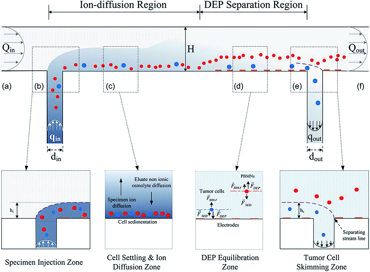
During the early days, CTC isolation using dielectrophoresis was only carried out with microelectrodes, which showed disadvantages such as cell cleavage, low cell discrimination and throughput.75 To address this issue, Shim et al.76 developed continuous dielectrophoretic field flow fractionation (DEP-FFF) to isolate CTCs. Initially, batch mode of DEP-FFF was used to attain the discrimination between cells, however the device lacked in high throughput as it took several days to isolate very few rare cells from 4 × 10⁷ of RBCs.77 To allow larger batches of cells to be processed with higher discrimination, the continuous flow DEP-FFF was introduced where the isolation takes place in less than 1 h. The working principle of continuous flow DEP-FFF is presented in Fig. 7, briefly, there are two main regions in the device: one is ion-diffusion region and DEP separation region. Continuous flow of a low conductivity elute was passed from an inlet ‘a’ to an outlet ‘f’, establishing a Poiseuille flow profile in separation channel of 200 mm length, 25 mm width and 314 μm height with 50 μm parallel gold coated copper microelectrodes. Peripheral blood mononuclear cells (PBMNs) having CTCs (specimen) were fed through a slot in the bottom of the chamber at a continuous flow rate qin designated as specimen injection zone ‘b’ has a low flow rate compared to elute flow rate Qin which enables to form a thin specimen lamina that flows adjacent to the floor of the chamber beneath the main elute flow stream. Further when thin specimen lamina travels along the chamber floor in ion-diffusion region, cells experience sedimentation and weak hydrodynamic lift forces and settles close to the chamber floor ‘c’. Meanwhile, ions diffuse from thin specimen lamina into the main eluate flow stream, while non-ionic cells flows through specimen lamina. After flowing to sufficient distance along the chamber for diffusion, the specimen will be small enough to carry out DEP separation. The flow then enters DEP separation region, where AC voltage was supplied to microelectrodes on chamber floor to impose DEP forces on cells. As they flow over the microelectrodes, tumour cells are pulled towards chamber floor by positive DEP forces, while PBMNs are repelled and levitated by negative DEP forces due to their size differences. Cells eventually move to heights at which the DEP, sedimentation and hydrodynamic lift forces balance ‘d’. Finally, as flow enters the tumour cell skimming zone ‘e’, fluid is withdrawn through a slot in the chamber floor at a rate qout, tumour cells are thereby captured through the withdrawal slot, while PBMNs flow over the slot and exit to waste with the main eluate (qout) ‘f’. The crossover frequency (is the frequency where the DEP force makes the transition from negative to a positive force and is dependent on cell and medium conductivity and permittivity) used for isolation was 130 kHz at an applied voltage of 4 V. The device was tested with clinical samples: MDA-MB-45 cells with pre-labelled fluorescent dyes spiked in PBMNs specimen, more than 75% isolation efficiency was observed.
 | ||
| Fig. 7 Continuous dielectrophoretic field flow fractionation (DEP-FFF) microfluidic device (reproduced from ref. 76 with permission. Copyright© 2013 American Institute of Physics). | ||
ApoStream™ device which has been commercialized, consists of a gear pump, custom-made DEP signal generator, conductivity meter and laser particle counter which are computer controlled to enable dynamic feedback control and monitoring.78 The sample injection and collection flow rates are controlled by high precision syringe pumps. Mainly there are three components in the fabricated device; (i) a flexible polyimide film sheet with electroplated copper and gold electrodes which forms the floor, (ii) an acrylic sheet forms the ceiling and (iii) a gasket forms side walls of flow channel (Fig. 8). The sample is flowed through a rectangular port located in the bottom of flow chamber at upstream end. Cancer cells are collected through another rectangular port located downstream from sample inlet port. The sample is injected at a low flow rate to ensure cells stay within the effective DEP field. When cells come in contact with DEP field, the cancer cells were pulled towards chamber floor and repel other cells as they traverse the electrode. Cancer cells travelling close to chamber floor are collected at collection port, while other blood cells traveling at greater heights are carried beyond this port and exit the chamber to waste container (Fig. 8). The captured cancer cells are collected into a microcentrifuge tube. This device is capable of separating tumour cells at lower frequency i.e. 45 to 65 kHz with 40 kHz cross over frequency. Initially the optimization of the device was carried out to prevent cell levitation, cell skimming etc. It was also found that, the effect of DEP field decreases beyond ∼30 μm distance from bottom of the chamber,79 for this reason, flow rates were optimised in the region of ∼30 μm above the chamber flow to prevent from cell levitation. Ovarian cancer cells (SKOV-3) and breast cancer cells (MDA-MB-231) in peripheral blood mononuclear cells (PBMCs) were used for the study. Above the cross over frequency, separation of maximum tumour cells due to increase in p-DEP were observed, only 3% of normal blood cells were recovered. The average recovery rate of tumour cells of SKOV-3 and MDA-MB-231 cell lines were ∼75 and 72%, respectively. At lower spiking rates, the average recovery rate was 68% (Table 1). Although, the efficiency was less compared to other microfluidic devices, throughput was much higher for this device (60 min to process 12 × 106 PBMCs from 7.5 mL of blood samples).
 | ||
| Fig. 8 ApoStream™ microfluidic device (reproduced from ref. 78 with permission. Copyright© 2012 American Institute of physics). | ||
| Number of spiked cancer cells | Cancer cells collected after ApoStream™ | % cancer cell recovery | Average % cancer cell recovery | |
|---|---|---|---|---|
| SKOV3 cells | 23 | 14 | 60.9 | 68.3 |
| 19 | 14 | 73.7 | ||
| 5 | 4 | 80.0 | ||
| 4 | 2 | 50.0 | ||
| MDA-MB-231 cells | 22 | 16 | 72.7 | |
| 21 | 16 | 76.2 | ||
| 14 | 9 | 64.3 |
Unlike vertical levitation based isolation Das et al.80 reported a microfluidic device that consists of three planar electrodes for manoeuvring the cells horizontally. Central electrode is tapered at an angle of 9° with a width of 100 μm at the inlet, 1.1 mm at outlet spreading over 3 mm along the channel length. Two side electrodes of 50 μm width at the same tapering angle were also integrated. A continuous gap of 50 μm between electrodes maintain the flow of cells. Microchannels are covered with a transparent material to monitor the flow of cells. The planar design of electrode has an advantage that it won't block or act as a barrier to cells, which also leads to usage of lower voltage and enables to isolate cells. In presence of non-uniform electric field the separation can be with continuous flow pattern in a device. HeLa cells were used for real test where, tumour cells flow through the central electrode in the frequency range of 100 to 400 kHz, but when the frequency reaches 500 kHz the cells started moving towards the side electrodes. Finally, in the range of 700 kHz to 1 MHz, maximum number of HeLa cells move along the side electrodes, polystyrene beads flow only over central electrode. This is also well matched with theoretical results found through simulation.
Guo et al.81 reported circuit based microfluidic device which consists of three reservoirs, two electrodes inserted in left and right side of the device channels, one side branch channel acting as a conducting electrode and sensing aperture (Fig. 9). Working principle of this device is based on Coulter principle i.e. bias-voltmeter was used for counting and enumerating microparticles. Fluid containing particles block micro-scale aperture during translocation due to the obstacle of particles, thus, electric impedance of aperture increases which causes increase in electrical current across the fluidic branch for efficient sorting. By distinguishing dynamic change in bias pulse, the particle size and translocation time can be analysed. Single pulse corresponds to interaction of single particle, the higher pulse amplitude implies larger particles. Due to larger size of CTCs compared to RBCs, CTCs shows higher peak amplitude compared to RBCs.
 | ||
| Fig. 9 Circuit based microfluidic device. Inset: the real time image of the device in comparison with 9 mm diameter dollar coin (reproduced from ref. 81 with permission. Copyright© 2013 IEEE). | ||
Another device called multi-orifice flow fractionation (MOFF) has been introduced by Moon et al.,82 in which micro-particles were moved sideways due to hydrodynamic inertial force created by a multi orifice structure. The extent of sideways movement varies according to particle size and hence polymer microspheres used of different size can be held at different positions in a microchannel in the presence of DEP force. As discussed before, the DEP method lacks in efficiency and throughput at weak DEP force.83 To overcome this, MOFF and DEP techniques have been integrated in a single device (Fig. 10A). The MOFF component is composed of one inlet, a filter, a multi-orifice segment which contains 80 repeated contraction channels and expansion chambers with overall length of 36 mm, a fraction segment and two wide outlets. The channel dimension of 6 mm in width and 30 mm in length was adopted for DEP separation. The DEP electrodes were placed at bottom of the channel with an interdigitated structure of 40 mm in width. The blood cells and CTCs pass through MOFF, CTCs with some residual blood cells were get separated (i.e. specific ranges of Reynolds numbers for which the cells would be concentrated were separated laterally according to their sizes in the MOFF microchannel). It shows that RBCs recovered at higher Re (i.e. Rec = 70) not at lower Re (i.e. Rec = 30), whereas MCF-7 can be recovered at both low and high Rec. Around 93% MCF-7 cells from blood sample were isolated. While cells were in DEP region, where they experience dielectric force cells start moving towards the electrodes. At 900 kHz frequency, only MCF-7 cells were able to move towards electrodes and collected at outlet 2, whereas other blood cells flow in main channel and collected at outlet 3. MCF-7 cells were enriched 162 fold at flow rate of 126 μL min−1, with ∼95% separation efficiency to isolate RBCs and WBCs, but the efficiency of isolating CTCs was decreased to ∼78% due to two fold fractionation of samples.
 | ||
| Fig. 10 (A) Microfluidic device using multi-orifice flow fractionation (MOFF) and DEP for cell isolation (reproduced from ref. 82 with permission. Copyright© 2011 Royal Society of Chemistry). (B) Optical induced DEP (ODEP) device for cell isolation (reproduced from ref. 84 with permission. Copyright© 2013 Royal Society of Chemistry). | ||
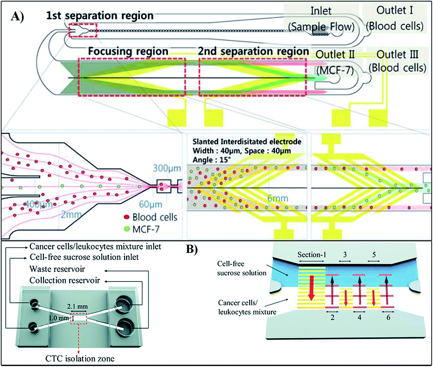
Optical based DEP (ODEP) with six sections of moving light-bar screens at cell isolation zone has been developed by Huang et al.84 to isolate CTCs with higher viability. Two inlets separated at 1.5 mm were designed for loading sterilized sucrose solution and mixture of cancer cells and leukocytes, respectively. The device with two microchannels of 7 mm length, 0.5 mm width and 50 mm height were intersected, the intersected area was called CTC isolation zone (2.1 mm in length and 1.0 mm in width). The moving light bars act as electrodes to isolate CTCs from whole blood. To create ODEP forces photoconductive material was used onto the light-bars. As shown in the Fig. 10B, sections 1, 3 and 5 direct the sample to CTCs isolation zone by creating ODEP forces, while sections 2, 4 and 6 to separate and guide cancer cells to the cell free sucrose channel (the purpose of sucrose solution is to maintain the osmotic condition which helps the cells viable). Prostate cancer cells (PC-3) and human oral cancer (OEC-M1) cell lines were used for isolation studies where cell recovery rate for PC-3 and OEC-M1 were ∼75 and ∼66% whereas cell viability for PC-3 and OEC-M1 cells were ∼94 and ∼95% respectively.
Chen et al.85 have improved isolation efficiency in comparison with the previous designs by adopting stepping electric field which was possible due to the spiral electrode design. The width of the electrodes and gap between them were 30 μm, the radius of circular microelectrode curvature was 1 mm. A circular electrode with diameter of 90 μm (lollipop shaped) was employed as central electrode to collect cells. To increase sample volume, open-top chamber made out of PDMS was fabricated and bonded to a glass substrate. HeLa and MCF-7 cell lines were spiked with RBCs to test the device. Before applying electric field, samples were randomly distributed over the surface, but as electric field comes in contact with cells, the cells experiences p-DEP (voltage 8 V and frequency 1 MHz). The electric field at adjacent electrodes were switched to generate stepping electric field form outmost electrode to central electrode, which was the driving force to concentrate the cells at the centre. The magnitude of DEP force acting on MCF-7 was 5 times more than that of HeLa cells because of large size of MCF-7 cells. The survival rate of RBCs after DEP force applied was very less whereas the average survival rates of HeLa and MCF-7 was as high as ∼82%. The cancer cells and RBCs concentration was set to 500 cells mL−1 and 4 × 10⁵ cells mL−1. Around 80% of both the cells were concentrated on central electrode.
Xing et al.86 designed an interdigitated comb like structure composed of 75 μm thick single crystal-doped silicon wafer that serves as both electrode and walls of active flow chamber. The electrode digits (15 pairs) display a characteristic layout featuring a set of alternatively arranged narrow (20 μm) and wide (140 μm) segments along the digit length (∼3 mm) (Fig. 11A). Beneath each narrow segment lies a round lateral opening (the ring) that is coaxially aligned with corresponding rings in all other digits for the purpose of defining an orthogonal flow path. The rings are nearly identical in size and feature a nominal diameter of 40 μm, which is large enough to allow passage of most blood cells and CTCs (human colorectal-carcinoma cells). Each digit containing 10 uniformly spaced rings contributes to a total of 300 rings across the device. Consequently, an input stream of cells gets divided equally into 10 parallel streams inside a large flow chamber (3 mm wide, 9 mm long) and exposed to an effective DEP force field through coaxial ring electrodes. This facilitates the use of a high cell-loading density (107 cells mL−1). The optimised frequency used to isolate CTCs from lymphocytes was 100 KHz at flow rate of 0.2 mL h−1, above and below this frequency it was observed that, very less isolation and removal of CTCs and lymphocytes respectively. At this frequency the rare cells experienced p-DEP force and separated from lymphocytes and collected at the electrode. The CTCs recovery rate achieved was ∼82% whereas ∼90% of blood lymphocytes were also separated from sample during the isolation simultaneously. Recovered viable cells were up to 94% as seen in SEM images.
 | ||
| Fig. 11 (A) Microfluidic device for the isolation of human colorectal-carcinoma cancer cells (reproduced from ref. 86 with permission. Copyright© 2014 Elsevier B.V.). (B) 3D lateral dielectrophoretic device for cell isolation (reproduced from ref. 87 with permission. Copyright© 2015 Royal Society of Chemistry). | ||
Recently, very high throughput 3D lateral dielectrophoretic (LDEP) microfluidic device has been introduced.87 The device has ‘V’ shaped microchannel with high electric field gradient that makes lateral DEP force normal to continuous flow (Fig. 11B). Cells with different sizes, dielectric properties and shapes show different LDEP velocities which resulted in the isolation. The 6 cm long device was subjected for its efficiency by using PC14PE6/AS2-GFP (AS2-GFP) lung cancer cells: the recovery rate was 85% with enrichment factor of 105 at the flow rate of 20 μL min−1 with average frequency of 10 kHz. By increasing the channel length to 13 cm throughput was about 24 mL h−1 which is significantly high.
DEP technique exploits differences in both cellular morphology and dielectric properties. It was assumed that, it could achieve high isolation efficiency and purity compared to size based isolation devices, however, when it comes to real time application this technique provides slightly less efficiency and purity due to limited dielectric difference between normal cells and CTCs. Also, using complex electronic equipment makes it less favourable. The flow rate and cell purity are in trade-off, as the flow rate increases, the purity decreases and vice versa. Furthermore, most of the reported on-chip DEP separation microfluidic devices require the use of a low conductivity medium which also limits the cell viability after separation. The cross over frequency is also an important factor in this method where reducing this frequency for higher isolation efficiency is challenging. For example, Shim et al.76 isolated CTCs with an efficiency of 75% at a frequency of 130 kHz whereas Moon et al.82 fabricated a device which has an efficiency of ∼90% at a cross over frequency of 900 kHz. However, to overcome the limitation of crossover frequency Gupta et al.78 developed a device called ApoStream™, which isolates CTCs at a frequency of ∼45 kHz and is relatively less. Recently Cheng et al.87 were able to isolate the CTCs at 10 kHz with the efficiency of ∼80% using 3D lateral based DEP device. Developing the integrated microfluidic devices which can give high isolation separation and purity at a time would be more favourable towards the commercialization of such devices.
4. Pinched flow based isolation
Pinched flow based isolation of CTCs were achieved in a microfluidic device which consists of a pinching region for trapping rare cells just prior to channel outlet. The width in pinching region is designed to be similar to the size of CTCs, such that the centre of inertia of these larger cells align along the axial centre of microchannel. Thus, at the outlet, all non-tumour cells remain along the side walls of channel, while larger CTCs are discharged along channel axial centre, allowing centre outlet to collect rare cells whereas most of the non-tumour cells are removed through side outlets. As shown in Fig. 12A provides a clear idea of pinched flow technique where, in pinched segment (a) particles align to one side of the wall without consideration of size which can be made possible by controlling flow rate. At broadened segment (b) particles were separated according to their sizes by spreading flow profile at the boundary of pinching segment which was due to laminar flow.88 In pinched flow isolation method the width of the pinching region is very essential feature as it varies with design parameters of the device according to the need of isolation of various sizes of CTCs.89 | ||
| Fig. 12 (A) Illustration of pinched flow based isolation of CTCs (reproduced from ref. 88 with permission. Copyright© 2004 American Chemical Society). (B) Pinched flow separation of CTCs using shear force (reproduced from ref. 90 with permission. Copyright© 2011 Royal Society of Chemistry). | ||
Bhagat et al.90 have adopted this technique, which consists of a single inlet, high aspect ratio rectangular microchannel patterned with a contraction–expansion array. The widths of the contraction and expansion regions were 20 and 60 μm respectively and their lengths were 100 μm. The microchannel consists of 75 subunits of contraction–expansion regions with a total length of 1.5 cm (a pair of contraction and expansion regions makes up one subunit). The outlet opens into a 300 μm wide section for enhanced visualization and is equally divided into three 100 μm wide bifurcating arms; two side outlets and a central outlet arm. The target cells are collected in centre outlet while all other blood components are removed from side outlets (Fig. 12B). The designed device utilizes shear modulated inertial lift produced by viscous drag and inertial lift force, which causes the cells to flow away from centre of channel towards wall of the microchannel and the wall induced force is generated as these particles move towards the wall. These two opposing forces results in equilibrium of uniform flow of cells. In other words, cells suspended in a fluid flowing through a microchannel are typically subjected to both viscous drag and inertial lift forces. The parabolic laminar velocity profile in plane Poiseuille flow produces a shear-induced inertial lift resulting in the particle migration away from the center of channel towards the wall of microchannel. As particles migrate closer to the walls, the asymmetric rotational force induced around particles generates a wall-induced lift force driving these particles away from the walls.91 This principle influences the efficient separation of rare cells as the channel width will be comparable to the sizes of CTCs. MCF-7 and MDA-MB-231 cell lines were used for experiments wherein cell recovery rate was found to be more than 80%, enrichment of 3.5 × 10⁵ fold and 1.2 × 10⁴ fold for red blood cells and peripheral blood leucocytes (PBL), respectively, at a flow rate of ∼108 cells min−1.
Pinched flow based cell isolation depends on physical properties of the cells such as the dimensions of cells and device used. The major advantage of this technique is that the cells undergo less stress in comparison to the dielectrophoretic technique and hence would result in higher cell viability and purity, which is very ideal for further cellular studies. However, it requires higher processing time and could often lead to cell clogging at the pinching region. Bhagat et al.90 fabricated a device which showed 80% efficiency with relatively high flow rate of ∼108 cells min−1. However, further studies are required to address above mentioned limitations.
5. Acoustophoretic based isolation
This technique is based on the generation of ultrasonic resonances in microfluidic channels. Acoustic waves are used to manipulate the cells at micro-level for decades. Lenshof et al.92 reported the use of acoustic forces for the efficient sorting and enumeration of CTCs by means of acoustophoresis, where the differing acousto-physical properties of circulating tumour cells are explored as the basis for separation from other peripheral blood cells.93 Recently Destgeer et al.94 comprehensively reviewed recent developments in the use of surface acoustic waves based manipulation of microparticles. Cell size, cell mass density and cell compressibility are the three properties which influences the acoustic force on the cells. If any of these properties changes between two different cell types then it is possible to isolate the cells acoustophoretically. For a given volume, flow rate and a given acoustic field strength, the chip can selectively transfer the subset of cells having the highest acoustophoretic mobility to the central outlet.Augustsson et al.95 developed noncontact, label free acoustophoretic method for the separation of CTCs. The device was fabricated in such a way that the produced ultrasound vibrations will affect the separation of CTCs from blood cells, also the width of the microfluidic channel was chosen in such a way that the ultrasonic vibrations produce two acoustic pressure nodes across the width of the channel and an additional single acoustic pressure node in the vertical direction so that the acoustic force deflects the cells flowing through the channel (Fig. 13A). The average frequency used for the generation of ultrasounds at first channel was 4.97 MHz at voltage 8.5 V and at the second channel where the cell separation takes place the frequency was set to 2 MHz, which is due to the single acoustic pressure node at the centre of the channel. In this study DU145, PC3 and LNCaP cells were fixed with paraformaldehyde, recovery rate was ∼95% with purity of ∼96%, whereas for non-fixed, viable cells, cell recovery rate was 72.5 to 93.9% with purity of 79.6 to 99.7%. The same group reported single inlet and two outlet acoustophoretic device to isolate the prostate cancer cells (DU145) and they have successfully separated the CTCs with the efficiency of ∼87% at a flow rate of 100 μL min−1.96
 | ||
| Fig. 13 (A) Isolation of CTCs in the presence of ultrasonic vibrations produced outside the device (reproduced from ref. 95 with permission. Copyright© 2012 American Chemical Society). (B) taSSAW based device for the separation of rare tumour cells (reproduced from ref. 97 with permission. Copyright© 2014 PNAS). | ||
Further to increase the cell purity and viability, tilted angle standing surface acoustic waves (taSSAW) has been utilized.97 The working principle of this technique is shown in the Fig. 13B. The pressure created by acoustic waves are induced at a particular angle to fluid direction flow instead of parallel to each other which experiences both acoustic force and laminar drag force. The difference between these two forces gives position and movement of particles along the pressure nodal lines, which produces higher separation at certain angle at the flow direction. The time taken for the movement of particles at a distance perpendicular to flow is few times higher than the produced acoustic wavelength, which depends on channel design. The taSSAW technique requires longer channels for a better separation which increases sensitivity of isolation. The method uses several pressure nodes in the device for efficient separation.
The acoustic radiation force, generated from pressure distribution within microfluidic channel, pushes suspended particles towards pressure nodal or anti-nodal lines in taSSAW field, depending on the cell size and density. Through a numerically optimised device, separation of 2 μm and 10 μm beads was studied with efficiency as high as ∼99%, at flow velocity of ∼1.5 mm s−1 and 19.5 MHz working frequency. The performance of the device was tested by separating MCF-7 breast cells from normal leucocytes using an optimized design, guided by numerical simulation, with an angle of inclination of 15°. MCF cells of size ∼20 μm have been successfully separated from ∼12 μm leucocytes by this method. The recovery rate and purity achieved using this device is ∼71 and ∼84% respectively.
It is worth mentioning that the acoustophoretic based device for isolation of CTCs have not been explored to a great extent. Generally cells present in the region of acoustic wave will experience a radiation force. The direction of the movement depends on their inherent physical properties, such as the density, speed of sound along with properties of the surrounding medium. Utilization of precise device at a controlled ultrasound frequency helps to isolate tumour cells more efficiently. The theory behind the effect of ultrasound waves inside the microchannel for the isolation of CTCs is still at its infant stage. Augustsson et al.95 introduced a device which isolates CTCs with an efficiency of ∼95% at an ultrasound frequency of 4.9 MHz and voltage of 8.5 V. Further to increase the viability of cells, tilted angle standing acoustic waves has been used by Ding et al.97 where isolation efficiency was ∼71% at an angle of inclination 15° and an ultrasound frequency of 19.5 MHz whereas purity was found to be as high as ∼84%. Note that, ultrasound frequency is an important parameter to get high separation efficiency. Though the use of ultrasound waves were known decades back, the complete integration of this technique along with other techniques is yet to happen, to efficiently isolate the cells with efficiencies as high as in other methods discussed above.
6. Conclusion and future prospects
CTCs have been clinically studied for diagnosis and prognosis of cancer which is known as liquid biopsy and also play an important role in metastasis. It is well accepted that CTCs present very low in number at blood stream and upon isolating and subjecting to molecular assay, very important diagnostic information can be extracted. Microfluidic technology on the other hand has been extensively explored in biomedical applications including isolation of CTCs due to its several advantages over macroscale separation techniques like in CellSearch®. Numerous papers have reported in this field of isolation and detection of CTCs in a microfluidic format as lab-on-a-chip kind of devices.The existing detection and isolation techniques of CTCs are broadly classified as nucleic acid, physical property and antibody based methods. Nucleic acid based methods can only determine positivity of a sample i.e. the existence of tumour cells and it does not allow for the direct enumeration and morphological studies of the tumour cells. Physical property based methods are being studied extensively as they give several advantages such as easy sample preparation, cost effective devices and very high capturing efficiencies. Finally, antibody based methods were also been studied for isolation of rare tumour cells, but the disadvantage is that these methods are laborious and very expensive to perform. In this review we have summarised design perspective of microfluidic devices for label free isolation, detection of CTCs (i.e. use of physical properties of devices and biological cells for effective isolation of CTCs based on size differences, dielectrophoresis, pinched flow and acoustic methods).
Moreover, such devices can be cheaply fabricated due to the non-usage of expensive antibodies, reusability potential and hence such devices provides researchers to detect unidentified biological markers which can give breakthrough results in future. The standard protocol for efficient isolation, enumeration and characterization of CTCs is still missing. Coming up with a standard operating procedure (SOP) for this study is necessary as the design and strategy of isolation varies drastically from device to device. Only few devices are commercialised to date such as CellSearch®, ApoStream™, ISET® and Screencell®. Still, there is a huge scope for the commercialisation of a cheap microfluidic based devices for the isolation of rare cells which we expect are coming soon. In particular new 3D printing technology of transparent polymers with submicron resolution open enormous potential to produce microfluidic devices with complex structure very cheaply and we expect this technology will take an important role in development of new devices with advanced performances in near future.
Acknowledgements
Authors would like to acknowledge the Department of Science and Technology (DST), Govt. of India (DST/TM/WTI/2K14/213), Nanomission, DST, India (SR/NM/NS-20/2014) and Jain University, Bangalore, India for financial support. Authors would like to thank Prof Geetha Balakrishna, Director, CNMS, Jain University, Bangalore, India for the constant support.References
- M. Y. Ali, Int. J. Mech. Mater. Eng., 2009, 4, 93–97 Search PubMed.
- Y. S. Lin, C. H. Yang, C. Y. Wang, F. R. Chang, K. S. Huang and W. C. Hsieh, Sensors, 2012, 12, 1455–1467 CrossRef CAS PubMed.
- P. P. Shiu, G. K. Knopf, M. Ostojic and S. Nikumb, J. Micromech. Microeng., 2008, 18, 025012 CrossRef.
- B. G. Subramani and P. R. Selvaganapathy, J. Micromech. Microeng., 2009, 19, 015013 CrossRef.
- K. Sugioka, J. Xu, D. Wu, Y. Hanada, Z. Wang, Y. Cheng and K. Midorikawa, Lab Chip, 2014, 14, 3447–3458 RSC.
- N. S. Devaraju and M. A. Unger, Lab Chip, 2011, 11, 1962–1967 RSC.
- K. W. K. Pilnam Kim, M. Cheol Park, S. Hoon Lee, S. Min Kim and K. Yang Suh, BioChip J., 2008, 2, 1–11 Search PubMed.
- Q. Chen, Q. Chen and G. Maccioni, Curr. Appl. Phys., 2013, 13, 256–261 CrossRef PubMed.
- C. Duan, W. Wang and Q. Xie, Biomicrofluidics, 2013, 7, 26501 CrossRef PubMed.
- J. C. McDonald, D. C. Duffy, J. R. Anderson, D. T. Chiu, H. Wu, O. J. A. Schueller and G. M. Whitesides, Electrophoresis, 2000, 21, 27–40 CrossRef CAS.
- S. Kabiri, M. D. Kurkuri, T. Kumeria and D. Losic, RSC Adv., 2014, 4, 15276 RSC.
- E. Berthier, E. W. Young and D. Beebe, Lab Chip, 2012, 12, 1224–1237 RSC.
- T. Squires and S. Quake, Rev. Mod. Phys., 2005, 77, 977–1026 CrossRef CAS.
- J. Autebert, B. Coudert, F. C. Bidard, J. Y. Pierga, S. Descroix, L. Malaquin and J. L. Viovy, Methods, 2012, 57, 297–307 CrossRef CAS PubMed.
- T. Kumeria, M. D. Kurkuri, K. R. Diener, L. Parkinson and D. Losic, Biosens. Bioelectron., 2012, 35, 167–173 CrossRef CAS PubMed.
- M. D. Kurkuri, F. Al-Ejeh, J. Y. Shi, D. Palms, C. Prestidge, H. J. Griesser, M. P. Brown and B. Thierry, J. Mater. Chem., 2011, 21, 8841–8848 RSC.
- B. Thierry, M. Kurkuri, J. Y. Shi, L. E. Lwin and D. Palms, Biomicrofluidics, 2010, 4, 32205 CrossRef PubMed.
- E. K. Sackmann, A. L. Fulton and D. J. Beebe, Nature, 2014, 507, 181–189 CrossRef CAS PubMed.
- Z. Zhang and S. Nagrath, Biomed. Microdevices, 2013, 15, 595–609 CrossRef CAS PubMed.
- C. Zhang, J. Xu, W. Ma and W. Zheng, Biotechnol. Adv., 2006, 24, 243–284 CrossRef CAS PubMed.
- L. Wang and P. C. Li, Anal. Chim. Acta, 2011, 687, 12–27 CrossRef CAS PubMed.
- N. Han, J. H. Shin and K.-H. Han, RSC Adv., 2014, 4, 9160 RSC.
- D. Wu, J. Qin and B. Lin, J. Chromatogr. A, 2008, 1184, 542–559 CrossRef CAS PubMed.
- S. K. Sia and G. M. Whitesides, Electrophoresis, 2003, 24, 3563–3576 CrossRef CAS PubMed.
- S. A. Soper, K. Brown, A. Ellington, B. Frazier, G. Garcia-Manero, V. Gau, S. I. Gutman, D. F. Hayes, B. Korte, J. L. Landers, D. Larson, F. Ligler, A. Majumdar, M. Mascini, D. Nolte, Z. Rosenzweig, J. Wang and D. Wilson, Biosens. Bioelectron., 2006, 21, 1932–1942 CrossRef CAS PubMed.
- R. B. Fair, A. Khlystov, T. D. Tailor, V. Ivanov, R. D. Evans, V. Srinivasan, V. K. Pamula, M. G. Pollack, P. B. Griffin and J. Zhou, IEEE Design & Test of Computers, 2007, 24, 10–24 Search PubMed.
- R. Siddique and N. Thakor, J. R. Soc., Interface, 2014, 11, 1–13 Search PubMed.
- J. D. Chunxiao Hu, J. Kearn, C. Murray, V. O'Connor, L. Holden-Dye and H. Morgan, PLoS One, 2013, 8, 17 Search PubMed.
- R. C. Lo, J. Bioprocess. Biotech., 2012, 02, 1–2 Search PubMed.
- A. Grunberger, W. Wiechert and D. Kohlheyer, Curr. Opin. Biotechnol., 2014, 29, 15–23 CrossRef PubMed.
- Y. Chen, P. Li, P. H. Huang, Y. Xie, J. D. Mai, L. Wang, N. T. Nguyen and T. J. Huang, Lab Chip, 2014, 14, 626–645 RSC.
- C. de Martel, J. Ferlay, S. Franceschi, J. Vignat, F. Bray, D. Forman and M. Plummer, Lancet Oncol., 2012, 13, 607–615 CrossRef.
- K. Pantel and C. Alix-Panabieres, Trends Mol. Med., 2010, 16, 398–406 CrossRef PubMed.
- H. Esmaeilsabzali, T. V. Beischlag, M. E. Cox, A. M. Parameswaran and E. J. Park, Biotechnol. Adv., 2013, 31, 1063–1084 CrossRef CAS PubMed.
- C. Alix-Panabieres and K. Pantel, Clin. Chem., 2013, 59, 110–118 CAS.
- Y. Dong, A. M. Skelley, K. D. Merdek, K. M. Sprott, C. Jiang, W. E. Pierceall, J. Lin, M. Stocum, W. P. Carney and D. A. Smirnov, J. Mol. Diagn., 2013, 15, 149–157 CrossRef PubMed.
- P. Li, Z. S. Stratton, M. Dao, J. Ritz and T. J. Huang, Lab Chip, 2013, 13, 602–609 RSC.
- C. Costa, M. Abal, R. Lopez-Lopez and L. Muinelo-Romay, Sensors, 2014, 14, 4856–4875 CrossRef PubMed.
- J. Sastre, M. L. Maestro, A. Gomez-Espana, F. Rivera, M. Valladares, B. Massuti, M. Benavides, M. Gallen, E. Marcuello, A. Abad, A. Arrivi, C. Fernandez-Martos, E. Gonzalez, J. M. Tabernero, M. Vidaurreta, E. Aranda and E. Diaz-Rubio, Oncologist, 2012, 17, 947–955 CrossRef CAS PubMed.
- C. Alix-Panabieres and K. Pantel, Lab Chip, 2014, 14, 57–62 RSC.
- N. Gerges, J. Rak and N. Jabado, Br. Med. Bull., 2010, 94, 49–64 CrossRef PubMed.
- R. Harouaka, Z. Kang, S. Y. Zheng and L. Cao, Pharmacol. Ther., 2014, 141, 209–221 CrossRef CAS PubMed.
- L. R. Volpatti and A. K. Yetisen, Trends Biotechnol., 2014, 32, 347–350 CrossRef CAS PubMed.
- C. D. Chin, V. Linder and S. K. Sia, Lab Chip, 2012, 12, 2118–2134 RSC.
- L. Hajba and A. Guttman, TrAC, Trends Anal. Chem., 2014, 59, 9–16 CrossRef CAS PubMed.
- C. W. T. Shields, C. D. Reyes and G. P. Lopez, Lab Chip, 2015, 15, 1230–1249 RSC.
- L. Yu, S. R. Ng, Y. Xu, H. Dong, Y. J. Wang and C. M. Li, Lab Chip, 2013, 13, 3163–3182 RSC.
- P. Chen, Y. Y. Huang, K. Hoshino and X. Zhang, Lab Chip, 2014, 14, 446–458 RSC.
- J. Chen, J. Li and Y. Sun, Lab Chip, 2012, 12, 1753–1767 RSC.
- I. Cima, C. Wen Yee, F. S. Iliescu, W. M. Phyo, K. H. Lim, C. Iliescu and M. H. Tan, Biomicrofluidics, 2013, 7, 11810 CrossRef PubMed.
- R. A. Harouaka, M. Nisic and S. Y. Zheng, J. Lab. Autom., 2013, 18, 455–468 CrossRef CAS PubMed.
- P. Sajeesh and A. K. Sen, Microfluid. Nanofluid., 2013, 17, 1–52 CrossRef.
- J. P. Smith, A. C. Barbati, S. M. Santana, J. P. Gleghorn and B. J. Kirby, Electrophoresis, 2012, 33, 3133–3142 CrossRef CAS PubMed.
- J. Alvankarian, A. Bahadorimehr and B. Yeop Majlis, Biomicrofluidics, 2013, 7, 14102 CrossRef PubMed.
- M. E. Warkiani, B. L. Khoo, D. S. Tan, A. A. Bhagat, W. T. Lim, Y. S. Yap, S. C. Lee, R. A. Soo, J. Han and C. T. Lim, Analyst, 2014, 139, 3245–3255 RSC.
- M. E. Warkiani, G. Guan, K. B. Luan, W. C. Lee, A. A. Bhagat, P. K. Chaudhuri, D. S. Tan, W. T. Lim, S. C. Lee, P. C. Chen, C. T. Lim and J. Han, Lab Chip, 2014, 14, 128–137 RSC.
- S. Nagrath, L. V. Sequist, S. Maheswaran, D. W. Bell, D. Irimia, L. Ulkus, M. R. Smith, E. L. Kwak, S. Digumarthy, A. Muzikansky, P. Ryan, U. J. Balis, R. G. Tompkins, D. A. Haber and M. Toner, Nature, 2007, 450, 1235–1239 CrossRef CAS PubMed.
- J. Sun, C. Liu, M. Li, J. Wang, Y. Xianyu, G. Hu and X. Jiang, Biomicrofluidics, 2013, 7, 11802 CrossRef PubMed.
- T. Huang, C. P. Jia, Y. Jun, W. J. Sun, W. T. Wang, H. L. Zhang, H. Cong, F. X. Jing, H. J. Mao, Q. H. Jin, Z. Zhang, Y. J. Chen, G. Li, G. X. Mao and J. L. Zhao, Biosens. Bioelectron., 2014, 51, 213–218 CrossRef CAS PubMed.
- C. J. Wenjie Sun, T. Huang, W. Sheng, G. Li, H. Zhang, F. Jing, Q. Jin, J. Zhao, G. Li and Z. Zhang, PLoS One, 2013, 8, 9 Search PubMed.
- S. Shen, C. Ma, L. Zhao, Y. Wang, J. C. Wang, J. Xu, T. Li, L. Pang and J. Wang, Lab Chip, 2014, 14, 2525–2538 RSC.
- T. F. Takeshi Hayakawa, K. Ito, and F. Arai, Micro Electro Mechanical Systems (MEMS), 2014 IEEE 27th International Conference, 2014, p. 4 Search PubMed.
- T. M. Geislinger and T. Franke, Biomicrofluidics, 2013, 7, 44120 CrossRef PubMed.
- S. C. Hur, A. J. Mach and D. Di Carlo, Biomicrofluidics, 2011, 5, 22206 Search PubMed.
- E. Sollier, D. E. Go, J. Che, D. R. Gossett, S. O'Byrne, W. M. Weaver, N. Kummer, M. Rettig, J. Goldman, N. Nickols, S. McCloskey, R. P. Kulkarni and D. Di Carlo, Lab Chip, 2014, 14, 63–77 RSC.
- J. Zhou and I. Papautsky, Lab Chip, 2013, 13, 1121–1132 RSC.
- M. Hosokawa, H. Kenmotsu, Y. Koh, T. Yoshino, T. Yoshikawa, T. Naito, T. Takahashi, H. Murakami, Y. Nakamura, A. Tsuya, T. Shukuya, A. Ono, H. Akamatsu, R. Watanabe, S. Ono, K. Mori, H. Kanbara, K. Yamaguchi, T. Tanaka, T. Matsunaga and N. Yamamoto, PLoS One, 2013, 8, e67466 CAS.
- M. Hosokawa, A. Arakaki, M. Takahashi, T. Mori, H. Takeyama and T. Matsunaga, Anal. Chem., 2009, 81, 5308–5313 CrossRef CAS PubMed.
- D. L. Adams, P. Zhu, O. V. Makarova, S. S. Martin, M. Charpentier, S. Chumsri, S. Li, P. Amstutz and C. M. Tang, RSC Adv., 2014, 9, 4334–4342 RSC.
- Y. Tang, J. Shi, S. Li, L. Wang, Y. E. Cayre and Y. Chen, Sci. Rep., 2014, 4, 6052 CAS.
- X. Qin, S. Park, S. P. Duffy, K. Matthews, R. R. Ang, T. Todenhofer, H. Abdi, A. Azad, J. Bazov, K. N. Chi, P. C. Black and H. Ma, Lab Chip, 2015, 15, 2278–2286 RSC.
- H. A. Pohl, J. Appl. Phys., 1951, 22, 869 CrossRef CAS PubMed.
- W. S. Low and W. A. Wan Abas, BioMed Res. Int., 2015, 2015, 239362 Search PubMed.
- K. A. Hyun and H. I. Jung, Electrophoresis, 2013, 34, 1028–1041 CrossRef CAS PubMed.
- P. Gascoyne and S. Shim, Cancers, 2014, 6, 545–579 CrossRef PubMed.
- S. Shim, K. Stemke-Hale, A. M. Tsimberidou, J. Noshari, T. E. Anderson and P. R. Gascoyne, Biomicrofluidics, 2013, 7, 11807 CrossRef PubMed.
- P. R. Gascoyne, J. Noshari, T. J. Anderson and F. F. Becker, Electrophoresis, 2009, 30, 1388–1398 CrossRef CAS PubMed.
- V. Gupta, I. Jafferji, M. Garza, V. O. Melnikova, D. K. Hasegawa, R. Pethig and D. W. Davis, Biomicrofluidics, 2012, 6, 24133 Search PubMed.
- Y. Huang, X. B. Wang, F. F. Becker and P. R. Gascoyne, Biophys. J., 1997, 73, 1118–1129 CrossRef CAS.
- D. Das, K. Biswas and S. Das, Med. Eng. Phys., 2014, 36, 726–731 CrossRef PubMed.
- J. Guo, W. Lei, X. Ma, P. Xue, Y. Chen and Y. Kang, IEEE Transactions on Biomedical Circuits and Systems, 2014, 8, 35–41 CrossRef PubMed.
- H. S. Moon, K. Kwon, S. I. Kim, H. Han, J. Sohn, S. Lee and H. I. Jung, Lab Chip, 2011, 11, 1118–1125 RSC.
- H.-S. Moon, Y.-W. Nam, J. C. Park and H.-I. Jung, Environ. Sci. Technol., 2009, 43, 5857–5863 CrossRef CAS.
- S. B. Huang, M. H. Wu, Y. H. Lin, C. H. Hsieh, C. L. Yang, H. C. Lin, C. P. Tseng and G. B. Lee, Lab Chip, 2013, 13, 1371–1383 RSC.
- G.-H. Chen, C.-T. Huang, H.-H. Wu, T. N. Zamay, A. S. Zamay and C.-P. Jen, BioChip J., 2014, 8, 67–74 CrossRef CAS.
- X. Xing, R. Y. Poon, C. S. Wong and L. Yobas, Biosens. Bioelectron., 2014, 61, 434–442 CrossRef CAS PubMed.
- I. F. Cheng, W. L. Huang, T. Y. Chen, C. W. Liu, Y. D. Lin and W. C. Su, Lab Chip, 2015, 15, 2950–2959 RSC.
- M. Yamada, M. Nakashima and M. Seki, Anal. Chem., 2004, 76, 5465–5471 CrossRef CAS PubMed.
- J. F. Ashley, C. N. Bowman and R. H. Davis, AIChE J., 2013, 59, 3444–3457 CrossRef CAS PubMed.
- A. A. Bhagat, H. W. Hou, L. D. Li, C. T. Lim and J. Han, Lab Chip, 2011, 11, 1870–1878 RSC.
- L. Zeng, S. Balachandar and P. Fischer, J. Fluid Mech., 2005, 536, 1–25 CrossRef.
- A. Lenshof and T. Laurell, J. Lab. Autom., 2011, 16, 443–449 CrossRef CAS PubMed.
- X. Ding, P. Li, S. C. Lin, Z. S. Stratton, N. Nama, F. Guo, D. Slotcavage, X. Mao, J. Shi, F. Costanzo and T. J. Huang, Lab Chip, 2013, 13, 3626–3649 RSC.
- G. Destgeer and H. J. Sung, Lab Chip, 2015, 15, 2722–2738 RSC.
- P. Augustsson, C. Magnusson, M. Nordin, H. Lilja and T. Laurell, Anal. Chem., 2012, 84, 7954–7962 CrossRef CAS PubMed.
- M. Antfolk, C. Antfolk, H. Lilja, T. Laurell and P. Augustsson, Lab Chip, 2015, 15, 2102–2109 RSC.
- X. Ding, Z. Peng, S. C. Lin, M. Geri, S. Li, P. Li, Y. Chen, M. Dao, S. Suresh and T. J. Huang, Proc. Natl. Acad. Sci. U. S. A., 2014, 111, 12992–12997 CrossRef CAS PubMed.
| This journal is © The Royal Society of Chemistry 2015 |