Iridium nanoparticles supported in polymeric membranes: a new material for hydrogenation reactions

Vinícius W. Faria, Marcos F. Brunelli and Carla W. Scheeren*
Laboratory of Catalysis, School of Chemistry and Food, Universidade Federal do Rio Grande-FURG, Rua Barão do Caí, 125, 95500-000 Santo Antônio da Patrulha, RS, Brazil. E-mail: carlascheeren@gmail.com

Received 14th August 2015 , Accepted 1st October 2015

First published on 1st October 2015


Abstract

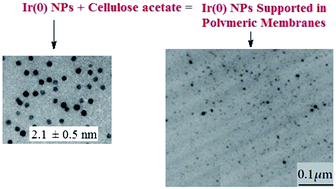
Iridium nanoparticles (Ir(0) NPs) of 2.1 ± 0.5 nm were synthesized from [Ir(cod)Cl]2 (cod = 1,5-cyclooctadiene) in the ionic liquid (IL) 1-n-butyl-3-methylimidazolium hexafluorophosphate [BMI.PF6]. The Ir(0) NPs were subsequently supported on polymeric membranes using cellulose acetate (CA) in acetone and the IL 1-n-butyl-3-methylimidazolium bis(trifluoromethane sulfonyl)imide [BMI.N(Tf)2]. Polymeric membranes with thicknesses of 20 μm were prepared with 10 mg of Ir(0) NPs. The polymeric membranes were characterized using X-ray diffraction (XRD), scanning electron microscopy (SEM), energy dispersive X-ray spectroscopy (EDS), and transmission electron microscopy (TEM). The analysis showed that the Ir(0) NPs are homogeneously distributed over the entire membrane, which has a compact structure. The presence of small Ir(0) NPs induced increases in the surface areas of the ​​polymeric membranes. The presence of the IL in the membrane structure increases the separation between the cellulose macromolecules, which results in greater flexibility and durability of the polymeric membranes. The CA/LI/Ir(0) combination exhibits excellent synergistic effects that increase the activity of the catalyst in hydrogenation reactions.

1. Introduction

Catalytic membranes have found applications in the fields of biotechnology, chemistry and petrochemistry.1,2 The application of catalytic membranes may have several advantages, such as easy preparation and lower cost for large scale use.3 Moreover, the unique structure of the catalytic membranes may have other additional advantages, such as immobilizing more active and selective metal nanoparticles with a reduction in particles loss, prevention of nanoparticles agglomeration, and the establishment of a porous contact region between the gas and liquid phases within the membrane structure.4 The intensive contact between the reactant mixture and the catalyst may lead to a higher conversion rate.

The use of active polymeric membranes5–9 has received little attention when compared with catalytically active inorganic membranes.10–13 However, inorganic membranes (albeit with high chemical and thermal stability)14 may be substituted by less expensive and more versatile polymeric organic membranes.6

The Supported Ionic Liquid Phase (SILP) is emerging as an interesting protocol for the immobilization of metal nanoparticles (MNPs) because it may combine the advantages of ionic liquids (ILs) with those of heterogeneous support materials.15,16 These materials are prepared via the covalent attachment of ILs to the support surface or by simply depositing the IL phases containing catalytically active species, usually transition metal complexes15 or metal nanoparticles16 on the surface of the support, which is usually a silica or polymeric material. Therefore, the combination of metal nanoparticles dispersed in an IL with a polymeric organic membrane, such as cellulose derivatives,17–22 may generate new and versatile catalytic materials.

For example, cellulose polymeric membranes were prepared via the combination of Rh or Pt NPs and the IL [BMI.N(Tf)2]. The catalyst showed superior activity in cyclohexene hydrogenation and possess higher stability than the metal NPs only.23 In another work, Pd NPs were supported in cellulose polymeric membranes. The material formed was applied in Suzuki coupling reactions with effective results.24 In another case, a poly(ionic liquid) was chemically grafted to a microPESs support membrane to stabilize Pd NPs. The well-defined Pd NPs immobilized inside the membrane provided catalytically active sites for the organic transformations.25

Iridium NPs synthesized in ILs with catalytic activity have been described in the literature.26–31 Different supports, such as silica, carbon, alumina and polyvinylpyrrolidone, have been studied to immobilize Ir NPs due the attractive properties of these materials.32–36

We report iridium NPs synthesized in the IL [BMI.PF6] combined with cellulose acetate in acetone and the IL 1-n-butyl-3-methylimidazolium bis(trifluoromethane sulfonyl)imide [BMI.N(Tf)2] for the generation of new polymeric membrane-supported Ir(0) NPs hydrogenation catalysts.

2. Experimental

2.1. General

All reactions were carried out under argon atmospheres in modified Fischer-Porter bottles. The halide-free ILs 1-n-butyl-3-methylimidazolium hexafluorophosphate [BMI.PF6] and 1-n-butyl-3-methylimidazolium bis(trifluoromethane sulfonyl)imide [BMI.N(Tf)2] were prepared according to known procedures and dried over molecular sieves (4 Å).37 Cellulose acetate (Aldrich, 39.8 wt% acetylation) and acetone (Merck, 99.8%) were used to prepare the polymeric membranes. All other chemicals were purchased from commercial sources and used without further purification. Gas chromatography analysis was performed with a Hewlett-Packard-5890 gas chromatograph with an FID and a 30 m capillary column with a dimethylpolysiloxane stationary phase. The nanoparticle syntheses were carried out in modified Fischer-Porter bottles. The temperature was maintained at 75 °C with a hot-stirring plate connected to a digital controller (ETS-D4 IKA).

2.2. Synthesis of Ir(0) nanoparticles

Ir(0) NPs were synthesized by simple hydrogen reduction (4 atm H2, constant pressure) using 0.027 g (0.1 mmol) of bis(1,5-cyclooctadiene)diiridium(I)dichloride [Ir(cod)Cl]2 dissolved in 1-n-butyl-3-methylimidazolium hexafluorophosphate [BMI.PF6] at 75 °C for 1 h to yield a black suspension. Acetone (15 mL) was then added, and centrifugation of this mixture yielded nanoparticles of 2.1 ± 0.5 nm.38

2.3. Preparation of polymeric membranes containing Ir(0) nanoparticles

Cellulose acetate (CA) (10.0 g) was added to a reaction flask containing 90 mL of acetone, and the mixture was allowed to sit for 24 h at room temperature under a dry nitrogen atmosphere. After a viscous syrup was formed, 10 mg (0.1 mmol) of Ir(0) NPs was dispersed in 5.0 g of the syrup cellulose acetate, forming the polymeric membrane designed CA/Ir(0). For the CA/IL/Ir(0) synthesis, 10 mg (0.1 mmol) of Ir(0) NPs dispersed in 1.0 g of [BMI.N(Tf)2] was used and added to 5.0 g of the syrup. The mixtures were magnetically stirred until a homogeneous solution was obtained. The polymeric membranes were prepared by spreading the solutions over a glass plate; 1300 mg was obtained. The thickness was controlled to 20 μm using a spacer. The solvent was evaporated in an open atmosphere for 2 min. A similar method was used to prepare a blank (CA) polymeric membrane without the use of Ir(0) NPs.39,40 The Ir(0) NPs supported polymeric membranes were applied in hydrogenation reactions.

2.4. X-ray powder diffraction analysis (XRD)

The phase structures of the Ir(0) NPs synthesized in [BMI.PF6] were characterized using XRD. For the XRD analysis, the Ir(0) NPs were isolated as a fine powder and placed in the sample holder. The XRD experiments were carried out on a SIEMENS D500 diffractometer using the Bragg–Brentano geometry equipped with a curved graphite crystal as the monochromator using Cu Kα radiation (λ = 1.5406 Å). The diffraction data were collected at room temperature in Bragg–Brentano θ–2θ geometry. The equipment was operated at 40 kV and 20 mA with a scan range between 20° and 90°. The diffractograms were obtained with a constant step of Δ2θ = 0.05. The indexation of the Bragg reflections was obtained via pseudo-Voigt profile fitting using the FULLPROF code.41

2.5. Scanning electron microscopy (SEM) and electron dispersive spectroscopy (EDS)

The morphology of the polymeric membranes CA/Ir(0) and CA/IL/Ir(0) and the electron dispersive spectroscopy analysis (EDS) was performed using a JEOL model JSM 5800 at 10 and 20 kV and magnification of 1000×.

2.6. Mechanical properties

The stress–strain behaviors of the polymeric membranes were analyzed using a Dynamic Mechanical Analyzer (DMA Q800 V7.0), TA Instruments, in the tension film geometry under isothermal temperature conditions (35 °C). These experiments were performed using a control rate force (2 N min−1) with an upper force limit of 20.00 N in films with a rectangular shape. The Young's modulus, tensile stress and strain to break were calculated from the stress–strain curves obtained from the measurement.

2.7. Transmission electron microscopy analysis (TEM)

TEM was performed using a JEOL JEM1200EXII operating at 120 kV. A 20 μm objective aperture and slightly under focused (Δf ≈ −300 nm) objective lens were used to obtain the bright field TEM images. The morphology and electron diffraction (ED) of the isolated Ir(0) NPs supported on the polymeric membrane were analyzed by TEM. The samples were prepared via deposition of the Ir(0) NPs in isopropanol at room temperature onto carbon-coated copper grids. The histograms of the NP size distribution were obtained from measurements of approximately 300 diameters (assuming a spherical shape) and were reproduced in different regions of the Cu grid. For the analyses of the Ir(0) NPs supported in the polymeric membranes, the material was immobilized in resin and sliced using ultramicrotomy and placed on a carbon-coated copper grid.

2.8. N2 adsorption–desorption isotherms

The specific surface area and pore size distribution of the CA/Ir(0) and CA/IL/Ir(0) polymeric membranes were determined at the nitrogen boiling point in a home-made volumetric apparatus with a vacuum line system employing a turbo molecular Edward vacuum pump, operating at a temperature of 110 °C for 2 h. The pressure measurements were made using a capillary Hg barometer. The specific surface areas and pore size of the CA/Ir(0) and CA/IL/Ir(0) polymeric membranes were determined from the BET multipoint method. The pore size distribution was obtained using the BJH method.42,43

2.9. Flame atomic absorption (FAAS)

The iridium contents in the polymeric membranes CA/Ir(0) and CA/IL/Ir(0) were measured using a Perkin-Elmer (Boston, MA, United States) flame atomic absorption spectrometer, model Analyst 200 (FAAS), using an air–acetylene (10[thin space (1/6-em)]:[thin space (1/6-em)]2.5 l min−1) flame under optimized conditions. Hollow cathode lamps of Iridium (λ = 208.88 nm) from the same manufacturer were used as radiation sources.

2.10. Hydrogenation reactions

The hydrogenation reactions using the CA/Ir(0) and CA/IL/Ir(0) polymeric membranes were carried out in a modified Fischer-Porter bottle immersed in a silicon oil bath connected to a hydrogen tank. The decrease in the hydrogen pressure in the tank was monitored with a pressure transducer interfaced through a Novus converter to a PC, and the data workup was performed using Microcal Origin 5.0 software. For the hydrogenation reaction, 210 mg of CA/Ir(0) or CA/IL/Ir(0) was utilized in the reactor. The polymeric membranes were placed in a Fischer-Porter bottle and 1-hexene, cyclohexene or benzene were added [ratio 250 mmol substrate/mmol Ir(0)]. The reactor was placed in an oil bath at 75 °C, and hydrogen was admitted into the system at constant pressure (4 atm H2). The organic products were removed via simple decantation and analyzed by GC.

3. Results and discussion

The Ir(0) NPs were synthesized by reduction of organometallic precursor [Ir(cod)Cl)]2 (cod = 1,5-cyclooctadiene) in 1-n-butyl-3-methylimidazolium hexafluorophosphate [BMI.PF6] IL at 75 °C under 4 atm of hydrogen. These nanoparticles were isolated from the IL and characterized by XRD (Fig. 1) and TEM analyses (Fig. 2).
image file: c5ra16426e-f1.tif
Fig. 1 XRD analysis of Ir(0) NPs synthesized in IL [BMI.PF6] (at 75 °C and 4 atm H2).

image file: c5ra16426e-f2.tif
Fig. 2 TEM micrograph of (A) Ir(0) NPs and (B) histogram the particle size distribution.

The Ir(0) NPs were irregularly shaped with a monomodal size distribution of 2.7 ± 0.5 nm (Fig. 2). The NPs were dispersed in the IL [BMI.N(Tf)2] and transferred as a syrup in cellulose acetate (CA) in acetone. This homogeneous solution was spread over a glass plate, and polymeric membranes with thicknesses of 20 μm were obtained using a spacer. The combination of CA/IL/Ir(0) may have several advantages, such as potentially using fixed-bed reactors for continuous reactions44,45 reducing IL levels and allowing for facile and efficient separation of products from catalyst. In this work, we have prepared polymeric membranes of cellulose acetate in acetone and the IL [BMI.N(Tf)2] containing supported Ir(0) NPs. The polymeric membranes formed were characterized using TEM, SEM/EDS, BET analyses, and the mechanical properties were investigated.

The XRD pattern (Fig. 1) confirmed the crystallinity of the iridium, and the mean diameter could be estimated from the XRD diffraction pattern by means of the Debye–Scherrer equation calculated from the full width at half-maxima (fwhm) of the (111), (200), (220), (311), and (222) planes. The diameter obtained from the XRD analysis was 2.7 ± 0.5 nm.

TEM analysis of the Ir(0) NPs show that the particles display a spherical shape; the evaluation of their characteristic diameter results in a monomodal particle size distribution (Fig. 2A). A mean diameter of 2.1 ± 0.5 nm Ir(0) NPs was estimated from an ensembles of 300 particles found in an arbitrarily chosen area of the enlarged micrographs. Fig. 2B shows the particle size distributions, which can be reasonably well fitted by a Gaussian curve.

The diameters of the Ir(0) NPs determined from the XRD (2.7 ± 0.4 nm) and TEM (2.1 ± 0.5 nm) analyses were different. The use of the full width at half maximum (fwhm) of a peak to estimate the size of the crystalline grain via the Scherrer equation has serious limitations because it does not take into account the existence of a distribution of sizes and the presence of defects in the crystalline lattice. Therefore, the calculation of average diameter of grain from the fwhm of the peak can overestimate the real value because the larger grains contribute strongly to the intensity, while the smaller grains only increase the base of the peak.

The polymeric membranes containing supported Ir(0) NPs were characterized by TEM (Fig. 3).


image file: c5ra16426e-f3.tif
Fig. 3 TEM micrographs of CA/IL/Ir(0) polymeric membranes.

The TEM micrographs of CA/IL/Ir(0) polymeric membranes (Fig. 3) show that the Ir(0) NPs are homogeneously distributed over the membrane (black points). This is an indication that the immobilization of the NPs does not significantly change the aggregation and size distribution of the nanoparticles in the IL.

The scanning electron micrographs (SEM) and energy dispersive X-ray spectroscopy (EDS) of the cross sections of the CA/IL/Ir(0) are shown in Fig. 4.


image file: c5ra16426e-f4.tif
Fig. 4 (A) SEM micrographs of CA/IL/Ir(0) and (B) EDS showing iridium, S and F signals, indicating the presence of the NPs and IL [BMI.N(Tf)2] in the polymeric membranes.

The SEM micrographs (Fig. 4A) show that the CA/IL/Ir(0) polymeric membranes contain stains that are heterogeneously distributed over the entire membrane cross-section, indicating the presence of Ir(0) NPs (represented by the clear points (BSE method)). The CA/IL/Ir(0) polymeric membrane cross-section in Fig. 4A shows that the thickness was approximately 20 μm. The EDS analysis (Fig. 4B) shows iridium, S and F signals, indicating the presence of the NPs and the IL [BMI.N(Tf)2] in the polymeric membranes. The CA and CA/IL polymeric membranes were also analyzed by SEM/EDS. The micrographs showed the compact structure of the polymeric membrane, and EDS showed the S and F signals from the anion of the IL (Fig. S1). It is clear that the morphological structure of the polymeric membranes changes with or without the IL. In particular, the CA polymeric membrane (Fig. S2, A) seems to have a scaled structure. In contrast, the addition of the IL seems to generate a fibrous structure in the longitudinal direction of the CA/IL polymeric membrane (Fig. S2, B).

The BET surface areas of the (CA), CA/IL and CA/IL/Ir(0) polymeric membranes are summarized in Table 1.

Table 1 Surface areas and pore volumes of pure CA, CA/IL and CA/IL/Ir(0) polymeric membranes
Entry Polymeric membrane Ir(0) BMI.N(Tf)2 SBET
1 CA 192 m2 g−1
2 CA/Ir(0) 10 mg 114 m2 g−1
3 CA/IL 1.0 g 24 m2 g−1
4 CA/IL/Ir(0) 10 mg 1.0 g 92 m2 g−1


The surface area of the pure cellulose polymeric membrane (CA) was 192 m2 g−1 (±10%); after the addition of the [BMI.N(Tf)2] IL (1.0 g), it was 24 m2 g−1 (±10%), demonstrating a reduction in the superficial area when the IL was added. This result suggests that the addition of the IL results the occupation of the free pores in the polymeric membrane, especially in the predominant fraction. The N2 adsorption–desorption isotherms at very low relative pressures (Pie/Po < 0.2) exhibited high adsorption, confirming the microporous structure. In the case of the polymeric membrane containing Ir(0) NPs, the surface area obtained was 114 m2 g−1 (±10%), and after the addition of the IL, a surface area of 92 m2 g−1 (±10%) was obtained. This result indicates that the presence of small Ir(0) nanoparticles induces an increase in the CA/IL polymeric membrane surface area (compare entries 3 and 4, Table 1). The concentration of Ir(0) NPs incorporated in the polymeric membrane was determined using FAAS. The concentrations were 762 μg g−1 and 0.08% (m m−1) for Ir(0). The metal concentration incorporated in the polymeric membrane is related to the thickness of the membrane; it was observed that, for thickness up to 20 μm, the materials is saturated by 10 mg of nanoparticles.46

The presence of the IL in the polymeric membranes was confirmed by the stretching band at 3170 cm−1, which is due to presence of aromatic C–H groups. After impregnation of the IL in the polymeric membranes, a significant decrease is observed in the intensity of the band at 3400 cm−1, which is attributed to the –OH stretching of the pure cellulose acetate, indicating participation of the –OH group in the interaction with the IL (see Fig. S3).

The tensile stress versus strain at break curves of the pure and modified polymeric membranes are shown in Fig. 5. Some of the main parameters that can influence the stress–strain curve profiles are the polymer structure, molecular weight, degree of cross-linking, chain orientation, ionic interaction, processing conditions and temperature, among others. The stress versus strain curves supplies important information about the Young's modulus (slope of linear region of the plot), tenacity, and stress and strain at break of polymeric membranes.


image file: c5ra16426e-f5.tif
Fig. 5 Stress versus strain curves of the modified membranes showing the effects of the different compositions of the cellulose acetate membranes.

The stress–strain curves in Fig. 5 are similar for the CA/IL, CA/Ir(0) and CA/IL/Ir(0) polymeric membranes when compared to the pure CA polymeric membrane. These results show increases in elasticity, decreases in tenacity and toughness (area under the stress–strain curve), and reductions of the Young's moduli for the CA/Ir(0), CA/IL and CA/IL/Ir(0) polymeric membranes. The stress–strain curve profiles suggest that the addition of the IL leads to drastic decreases in the Young's modulus and the elongation at break. This result indicates that an increase in the distance between two cellulose macromolecules resulted in greater flexibility of the cellulose.

The plasticizer effect of the IL [BMI.N(Tf)2] in the CA-1.0 g IL polymeric membranes reduces the intermolecular forces that are usually present in the cellulose acetate. In other words, it is possible that the bis(trifluoromethane sulfonyl)imide anion of the IL strongly interacts with the hydrogen bond networks formed in the cellulose acetate chains through the nitrogen atom. These results are corroborated by the infrared spectra (Fig. S3).

The catalytic activities of the heterogeneous catalysts studied in this work were expressed using the turnover frequency (TOF); the TOF values were estimated for low substrate conversions (10%). These activities should also be corrected by the number of exposed surface atoms using the metal atom's magic number approach.47

The catalytic properties of the Ir(0), CA/Ir(0) and CA/IL/Ir(0) polymeric membranes were evaluated in hydrogenation reactions of 1-hexene at 4 bar of H2 and 75 °C (Table 2). The catalytic activity (TOF) was strongly influenced by the applied catalyst.

Table 2 Hydrogenation of 1-hexene with Ir(0), CA/Ir(0) and CA/IL/Ir(0) polymeric membranesd
Entry Sample Substrate Ir(0) (mg) Timea (h) TOFb (h−1) TOFc (h−1)
a Time for 10% substrates conversion (determined by GC).b TOF values for 10% conversion.c TOF corrected values ​​for surface exposed atoms of iridium (45%).d Conditions: IL: [BMI.N(Tf)2]; TON = 250 mmol substrate/mmol Ir(0); 75 °C; 4 bar H2.
1 Ir(0) 1-Hexene 5 0.04 638 1417
2 CA/Ir(0) 1-Hexene 1.6 0.04 592 1317
3 CA/IL/Ir(0) 1-Hexene 1.6 0.03 750 1667
4 Ir(0) Cyclohexene 5 0.04 578 1284
5 CA/Ir(0) Cyclohexene 1.6 0.09 40 89
6 CA/IL/Ir(0) Cyclohexene 1.6 0.09 270 600
7 Ir(0) Benzene 5 0.1 266 591
8 CA/Ir(0) Benzene 1.6 1.46 18 40
9 CA/IL/Ir(0) Benzene 1.6 0.31 78 173


The catalytic properties of the Ir(0) NPs and the CA/Ir(0), and CA/IL/Ir(0) polymeric membranes were evaluated in hydrogenation reactions of 1-hexene, cyclohexene and benzene at 4 bar H2 and 75 °C (Table 2). The catalytic activity was strongly influenced by the catalyst used. For example, a higher catalytic activity (TOF) was observed for 1-hexene, cyclohexene and benzene using Ir(0) NPs (see entries 1, 4 and 7, Table 2). The activity of the Ir(0) NPs was lower than that of CA/IL/Ir(0) (compare entries 1 and 3, Table 2); this fact may be related to nanoparticle agglomeration, reducing the exposed area of the catalytically active species and causing a loss of catalytic activity. The TOF data indicate that the CA/IL/Ir(0) polymeric membranes are more active than those without the ionic liquid (compare entries 2 and 3, 5 and 6, 8 and 9, Table 2). This is an indication that there is a synergistic effect between the cellulose and the IL on the stabilization of the NPs. This result is in line with those results observed for other supported IL phase catalysts.48 The cellulose/IL ratio should be observed because membrane pore saturation may occur with higher molar concentrations of the IL. Therefore, levels of 1.0 g/5.0 g IL/cellulose guarantee NP stabilization and, most likely, the establishment of a more efficient porous contact region between the gas and the liquid phases within the polymeric membrane structure.49

Fig. 6 shows the hydrogenation curves of 1-hexene using Ir(0), CA/Ir(0) and CA/IL/Ir(0).


image file: c5ra16426e-f6.tif
Fig. 6 Hydrogenation of 1-hexene using Ir(0), IL/Ir(0), CA/Ir(0) and CA/IL/Ir(0).

The Ir(0) NPs and CA/Ir(0), CA/IL/Ir(0) polymeric membranes were evaluated in recyclability studies using 1-hexene as the substrate (Fig. 7).


image file: c5ra16426e-f7.tif
Fig. 7 Recyclability of the Ir(0), CA/Ir(0), and CA/IL/Ir(0) nanocatalysts as well as the commercial Crabtree catalyst in the hydrogenation of 1-hexene.

The recyclability studies included a commercial catalyst (Crabtree). Of note, the CA/IL/Ir(0) material can be reused up to 7 times in 1-hexene hydrogenation without losing catalytic activity (Fig. 7).

4. Conclusions

The combination of CA/IL/Ir(0) generated polymeric membranes with compact structures containing Ir(0) nanoparticles homogeneously distributed over the entire membrane. The introduction of the IL most likely caused an increase in the distance between the cellulose macromolecules, which results in higher polymeric membrane durability. The TOF results showed that the CA/IL/Ir(0) combination exhibit excellent synergistic effects that enhance the activity and durability (even after seven cycles) of the catalyst for the hydrogenation of 1-hexene.

Acknowledgements

Thanks are due to the following Brazilian Agencies: CNPq, CAPES and FAPERGS for fellowships and partial financial support.

Notes and references

  1. T. Westermann and T. Melin, Flow-through catalytic membrane reactors-principles and applications, Chemical Engineering and Processing: Process Intensification, 2009, 48, 17 CrossRef CAS PubMed.
  2. J. N. Armor, J. Membr. Sci., 1998, 147, 217 CrossRef CAS.
  3. C. P. Mehnert, Chem.–Eur. J., 2005, 11, 50 CrossRef PubMed.
  4. L. Cuffe, J. M. D. MacElroy, M. Tacke, M. Kozachok and D. A. Mooney, J. Membr. Sci., 2006, 272, 6 CrossRef CAS PubMed.
  5. M. A. Gelesky, S. S. X. Chiaro, F. A. Pavan, J. H. Z. dos Santos and J. Dupont, Dalton Trans., 2007, 5549 RSC.
  6. J. Coronas and J. Santamaria, Catal. Today, 1999, 51, 377 CrossRef CAS.
  7. A. Bottino, G. Capannelli, A. Comite, A. Del Borghi and R. Di Felice, Sep. Purif. Technol., 2004, 34, 239 CrossRef CAS.
  8. G. Centi and S. Perathoner, Catal. Today, 2003, 79, 3 CrossRef.
  9. J. Zaman and A. J. Chakma, J. Membr. Sci., 1994, 92, 1 CrossRef CAS.
  10. A. Riisager, R. Fehrmann, P. Wasserscheid and R. van Hal, in Ionic Liquids IIIB: Fundamentals, Progress, Challenges and Opportunities: Transformations And Processes, 2005, vol. 902, p. 334 Search PubMed.
  11. H. Kolding, A. Riisager and R. Fehrmann, Abstracts of Papers of the American Chemical Society, 2014, vol. 247, p. 16 Search PubMed.
  12. L. Foppa, J. Dupont and C. W. Scheeren, RSC Adv., 2014, 4, 16583 RSC.
  13. A. Riisager, R. Fehrmann, M. Haumann and P. Wasserscheid, Eur. J. Inorg. Chem., 2006, 4, 95 Search PubMed.
  14. A. L. Y. Tonkovich, J. L. Zilka, D. M. Jimenez, G. L. Roberts and J. L. Cox, Chem. Eng. Sci., 1996, 51, 789 CrossRef CAS.
  15. C. P. Mehnert, E. J. Mozeleski and R. A. Cook, Chem. Commun., 2002, 24, 3010 RSC.
  16. C. P. Mehnert, Chem.–Eur. J., 2004, 11, 50 CrossRef CAS PubMed.
  17. C. W. Scheeren, V. Hermes, O. Bianchi, P. F. Hertz, S. L. P. Dias and J. Dupont, J. Nanosci. Nanotechnol., 2011, 11, 5114 CrossRef CAS PubMed.
  18. V. W. Faria, D. G. M. Oliveira, M. H. S. Kurz, F. F. Gonçalves and G. R. Rosa, RSC Adv., 2014, 4, 13446 RSC.
  19. M. Bagheri and S. Rabieh, Cellulose, 2013, 20, 699 CrossRef CAS.
  20. M. Kaushik, H. M. Friedman, M. Bateman and A. Moores, RSC Adv., 2015, 5, 53207 RSC.
  21. L. Hardelin and B. Hagstrom, J. Appl. Polym. Sci., 2015, 132, 41417 CrossRef PubMed.
  22. H. Li, Q. Y. Zhang, A. Riisager and S. Yang, Curr. Nanosci., 2015, 11, 1 CrossRef CAS.
  23. M. B. Turner, S. K. Spear, J. D. Holbrey, D. T. Daly and R. D. Rogers, Biomacromolecules, 2005, 6, 2497 CrossRef CAS PubMed.
  24. V. W. Faria, D. G. M. Oliveira, M. H. Kurz, F. F. Gonçalves, C. W. Scheeren and G. R. Rosa, RSC Adv., 2014, 4, 13446 RSC.
  25. Y. M. A. Yamada, T. Watanabe, T. Beppu, N. Fukuyama, K. Torii and Y. Uozumi, Chem.–Eur. J., 2010, 16, 1131 CrossRef PubMed.
  26. P. Migowski, D. Zanchet, G. Machado, M. A. Gelesky, S. R. Teixeira and J. Dupont, Phys. Chem. Chem. Phys., 2010, 12, 6826 RSC.
  27. P. Migowski and J. Dupont, Chem.–Eur. J., 2007, 13, 32 CrossRef CAS PubMed.
  28. G. S. Fonseca, G. Machado, S. R. Teixeira, G. H. Fecher, J. Morais, M. C. M. Alves and J. Dupont, J. Colloid Interface Sci., 2006, 301, 193 CrossRef CAS PubMed.
  29. G. S. Fonseca, J. B. Domingos, F. Nome and J. Dupon, J. Mol. Catal. A: Chem., 2006, 248, 10 CrossRef CAS PubMed.
  30. G. S. Fonseca, J. D. Scholten and J. Dupont, Synlett, 2004, 9, 1525 Search PubMed.
  31. G. S. Fonseca, A. P. Umpierre, P. F. P. Fichtner, S. R. Teixeira and J. Dupont, Chem.–Eur. J., 2003, 9, 3263 CrossRef CAS PubMed.
  32. A. B. Dongil, C. Rivera-Carcamo, L. Pastor-Perez, A. Sepúlveda-Escribano and P. Reyes, Catal. Today, 2015, 249, 72 CrossRef CAS PubMed.
  33. J. V. Rojas and C. H. Castano, J. Radioanal. Nucl. Chem., 2014, 302, 555 CrossRef CAS.
  34. O. Hernandez-Cristobal, G. Diaz and A. Gomez-Cortes, Ind. Eng. Chem. Res., 2014, 53, 10097 CrossRef CAS.
  35. F. Heroguel, D. Gebert, M. D. Detwiler, D. Y. Zemlyanov, D. Baudouin and C. Copéret, J. Catal., 2014, 316, 260 CrossRef CAS PubMed.
  36. F. Heroguel, G. Siddiqi, M. D. Detwiler, D. Y. Zemlyanov, O. V. Safonova and C. Copéret, J. Catal., 2015, 321, 81 CrossRef CAS PubMed.
  37. C. C. Cassol, G. Ebeling, B. Ferrera and J. Dupont, Adv. Synth. Catal., 2006, 348, 243 CrossRef CAS PubMed.
  38. J. Dupont, G. S. Fonseca, A. P. Umpierre, P. F. P. Fichtner and S. R. Teixeira, J. Am. Chem. Soc., 2002, 124, 4228 CrossRef CAS PubMed.
  39. E. A. Campos and Y. Gushikem, J. Colloid Interface Sci., 1997, 193, 121 CrossRef CAS.
  40. J. W. Kwon, S. H. Yoon, S. S. Lee, K. W. Seo and I. W. Shim, Bull. Korean Chem. Soc., 2005, 26, 837–840 CrossRef CAS.
  41. J. R. Carbajal, Short Reference Guide of The Program Fullprof, version 3.5, http://Ftp://charybde.saclay.cea.fr Search PubMed.
  42. E. P. Barrett, L. G. Joyner and P. P. Halenda, J. Am. Chem. Soc., 1951, 73, 373 CrossRef CAS.
  43. S. Brunauer, Langmuir, 1987, 3, 3 Search PubMed.
  44. M. Mahyari, A. Shaabani and Y. Bide, RSC Adv., 2013, 3, 22509 RSC.
  45. A. Riisager, R. Fehrmann, P. P. Wasserscheid and R. van Hal, in Ionic Liquids IIIB: Fundamentals, Progress, Challenges and Opportunities: Transformations And Processes, 2005, vol. 902, p. 334 Search PubMed.
  46. M. A. Gelesky and C. W. Scheeren, Polim.: Cienc. Tecnol., 2014, 24, 1 CrossRef.
  47. A. P. Umpierre, E. Jesús and J. Dupont, ChemCatChem, 2011, 3, 1413 CrossRef CAS PubMed.
  48. A. Riisager, R. Fehrmann, S. Flicker, R. van Hal, M. Haumann and P. Wasserscheid, Angew. Chem., Int. Ed., 2005, 44, 815 CrossRef CAS PubMed.
  49. J. Xu, A. Dozier and D. Bhattacharyya, J. Nanopart. Res., 2005, 7, 449 CrossRef CAS.

Footnote

Electronic supplementary information (ESI) available. See DOI: 10.1039/c5ra16426e

This journal is © The Royal Society of Chemistry 2015
Click here to see how this site uses Cookies. View our privacy policy here.