DOI:
10.1039/C5RA15936A
(Paper)
RSC Adv., 2015,
5, 93554-93562
Wear and friction behaviour of TiAl matrix self-lubricating composites filled with WS2, MoO3 or multilayer graphene
Received
9th August 2015
, Accepted 27th October 2015
First published on 27th October 2015
Abstract
To further understand the lubrication effects and mechanisms of lamellar solid lubricants, wear and friction behaviours of TiAl matrix self-lubricating composites (TMSC) filled with WS2, MoO3 or multilayer graphene (MLG) are comparatively investigated under different counterface materials. Tribological results indicate that wear and friction properties of TMSC are significantly improved by adding WS2, MoO3 or MLG. Specifically, TMSC filled with MoO3 (TM) have lower friction coefficients and wear rates than TMSC filled with WS2 (TW), while TMSC filled with MLG (TG) have the lowest friction coefficients and wear rates. Meanwhile, EPMA, AFM and FESEM analyses present significant differences in worn surfaces of TMSC. Definitely, the worn surfaces of TM exhibit lighter damage and comparatively more compact films than those of TW; in contrast, the worn surfaces of TG exhibit the lightest damage and the most compact films. It can be concluded that WS2, MoO3 and MLG actually possess different lubrication effects and mechanisms.
1. Introduction
Metal matrix self-lubricating composites possessing combinations of lower friction, better wear and oxidation resistance, which have extensive potential applications in friction devices in various machines and mechanisms, are an intense area of research for the scientists and engineers working in the field of tribology.1,2 Solid lubricants, such as WS2,3 hBN,4 ZnO,5 Ag6 etc., have been added into metal matrix self-lubricating composites in order to improve their anti-friction and anti-wear properties. Solid lubricant-rich films, which are beneficial to the improvement of anti-friction and anti-wear performances of composites, can be formed between contact surfaces during the friction process because of lamellar structure and softness of these solid lubricants.3,6 WS2, a typical representative of lamellar solid lubricants, is widely used in various space motion mechanisms due to its solid state lubricating properties. Its lubrication effects were mainly attributed to the layered structure in which an W layer was sandwiched between two hexagonally packed S layers, which were extensively investigated and well understood.3,7,8 However, it is well known that different lamellar solid lubricants possess different lubrication effects and their lubrication degrees are not identical in a way. Consequently, realizing their respective lubrication effects and optimizing them as solid lubricants can provide an effective way to enhance the anti-friction and anti-wear properties of composites, which will have broad application prospects and important engineering value to increase the lifetime and performance of mechanical systems.
Multilayer graphene (MLG), another lamellar solid lubricant, possesses extraordinary properties, such as high Young's modulus, high fracture strength, extreme thermal conductivity and super charge-carrier mobility.9,10 It is therefore believed to have high potential as an ideal solid lubricant, which has been used in different applications.11–13 Orthorhombic (α-MoO3), the other lamellar solid lubricant, is a thermodynamically stable phase with a crystallographic anisotropic structure. It has numerous potential applications in advanced technology field due to its specific structure and functional properties.14,15 Nevertheless, to the best of our knowledge, there has not been several studies in the open literature on friction and wear behaviors of metal matrix self-lubricating composites filled with MoO3 or MLG,11,16,17 especially no investigation comparing MoO3 and MLG to WS2 for their respective lubrication effects and mechanisms has been explored.
TiAl alloys have attracted tremendous attention due to their excellent properties, such as high melting point, low density, high strength and excellent oxidation resistance at high temperatures,18,19 which are widely used in the engineering applications covering gas turbine blades, engine exhaust valves, mechanical components in nuclear reaction, etc. Since sliding contact that is associated with wear and friction, occurs in many potential applications of TiAl alloys. Wear and friction behaviours are important properties need to be characterized for TiAl alloys. Consequently, wear and friction behaviours of TiAl matrix self-lubricating composites (TMSC) filled with WS2, MoO3 or MLG are comparatively investigated for the first time in the present work. Comparative investigations are expected to further acquire an in-depth understanding of respective lubrication effects of WS2, MoO3 and MLG as lamellar solid lubricants, and secondly to further enrich self-lubricating theories of composites filled with lamellar solid lubricant.
2. Experimental details
2.1. Material preparation
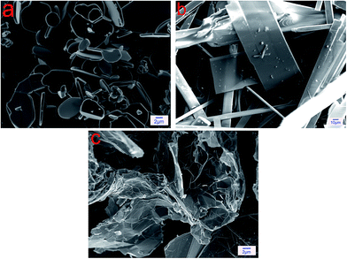
Ti (20 μm in average size), Al (20 μm in average size), Nb (10 μm in average size), Cr (10 μm in average size), B (25 μm in average size), WS2 (10 μm in average size), MLG (40 nm in average thickness, 50 μm in average lateral dimension) powders and MoO3 powders (25 μm in average length, 50 μm in average width) were used as the starting materials in this study. The composite powders of TMSC matrix consisted of Ti, Al, Nb, Cr and B powders with molar ratio of 48![[thin space (1/6-em)]](https://www.rsc.org/images/entities/char_2009.gif) :47:2:2:1.11 Microstructures and XRD patterns of solid lubricants are respectively presented in Fig. 1 and 3. Referring to some relevant literatures3,11,16,17 and our previous experiment data, we knew that low content of solid lubricant could improve the wear and friction properties of composites. Hence, for the purpose of comparison, the weight fractions of WS2, MoO3 and MLG were the same value of 3 wt% in the study. Herein, Ti–47Al–2Nb–2Cr–1B alloys were denoted as TiAl. Whilst TMSC filled with WS2, MoO3 and MLG were respectively denoted as TW, TM and TG. The starting powders were firstly mechanically mixed. After being mixed, the compound powders were put into cylindrical graphite mold with an inner diameter of 20 mm to be sintered by in situ technique using spark plasma sintering (SPS) in pure Ar atmosphere protection. The sintering parameters were: heating rate of 100 °C min−1, sintering temperature of 1100 °C, holding time of 6 min, and holding pressure of 35 MPa. Finally, the as-prepared samples surfaces were ground to remove the layers on the surfaces and polished mechanically with successive grades of emery papers to a surface roughness (Ra) of 0.05 μm.
:47:2:2:1.11 Microstructures and XRD patterns of solid lubricants are respectively presented in Fig. 1 and 3. Referring to some relevant literatures3,11,16,17 and our previous experiment data, we knew that low content of solid lubricant could improve the wear and friction properties of composites. Hence, for the purpose of comparison, the weight fractions of WS2, MoO3 and MLG were the same value of 3 wt% in the study. Herein, Ti–47Al–2Nb–2Cr–1B alloys were denoted as TiAl. Whilst TMSC filled with WS2, MoO3 and MLG were respectively denoted as TW, TM and TG. The starting powders were firstly mechanically mixed. After being mixed, the compound powders were put into cylindrical graphite mold with an inner diameter of 20 mm to be sintered by in situ technique using spark plasma sintering (SPS) in pure Ar atmosphere protection. The sintering parameters were: heating rate of 100 °C min−1, sintering temperature of 1100 °C, holding time of 6 min, and holding pressure of 35 MPa. Finally, the as-prepared samples surfaces were ground to remove the layers on the surfaces and polished mechanically with successive grades of emery papers to a surface roughness (Ra) of 0.05 μm.
 |
| | Fig. 1 FESEM micrographs of solid lubricants: (a) WS2; (b) MoO3; (c) MLG. | |
2.2. Relative density and microhardness
The relative density of each as-prepared composite was calculated using Archimedes' method. Seven tests were conducted to obtain reliable data and the average value was listed in Table 1. The microhardness of each as-prepared composite was determined using a HVS-1000 Vicker's hardness instrument with a constant load of 1 kg and a dwell time of 8 s. In order to contradict the possible effect of indenter resting on the harder reinforcement particles, seven locations were randomly chosen to test and the mean value was given in Table 1.
Table 1 Composition, relative density and microhardness of TMSC
| Composites |
Composition (wt%) |
Relative density (%) |
Vickers hardness (GPa) |
| TW |
TiAl–3WS2 |
95.52 |
5.28 |
| TM |
TiAl–3MoO3 |
96.13 |
5.37 |
| TG |
TiAl–3MLG |
96.02 |
6.68 |
2.3. Wear test
Sliding wear tests were carried out in ambient air on a HT-1000 ball-on-disk high temperature tribometer (made in Zhong Ke Kai Hua Corporation, China). The disks were made of the as-prepared composites. Commercially available balls of GCr15 steel (9.0 GPa, Ra of 0.01 μm), Si3N4 (15.0 GPa, Ra of 0.01 μm), Al2O3 (20.5 GPa, Ra of 0.01 μm) and WC-6Co (16.0 GPa, Ra of 0.01 μm) with 6 mm in diameter were chose as counterface balls.11 Testing parameters were: room temperature (RT), 10 N load, 0.2 m s−1 speed and 80 min testing time. The surfaces of disks and counterface balls were cleaned ultrasonically with acetone and thoroughly dried before testing. Friction coefficient was recorded automatically, and the value at the steady-state sliding was reported herein. Wear rate was calculated by the following formula:where V was the wear volume in mm3, P was the applied load in N and S was the total sliding distance in m. Wear volume was calculated using the equation:where V was the wear volume in mm3, A was the cross-section area of the wear track in mm2 and the perimeter of the wear track L in mm. The cross-section area A of wear track was measured using the three-dimensional profilometer (Nanovea, ST400) and given in Fig. 2. Seven tests were conducted for each set of testing parameters and the arithmetic mean values were calculated from the data of the five tests, making sure the reliability of the data.
 |
| | Fig. 2 Three-dimensional profile image of wear track. | |
2.4. Microstructure characterization
The phase compositions of solid lubricants and as-prepared TMSC were analyzed by XRD studies with CuKα radiation at 30 kV and 40 mA at a scanning speed of 0.01° s−1. The morphologies of WS2, MoO3 and MLG were characterized using field emission scanning electron microscope (FESEM). The morphologies and element chemical states of worn surfaces of TMSC were characterized using electron probe microanalyzer (EPMA), energy dispersive spectroscopy (EDS), atomic force microscope (AFM), Raman spectroscopy and FESEM. The cross-sections of pre-test and post-test TW, TM and TG were also characterized using FESEM in order to further observe the microstructures of TW, TM and TG.
3. Results and discussion
3.1. Pre-test characterization
Table 1 lists the composition, relative density and microhardness of as-prepared composites prepared in the present study. Compared with the microhardness of TiAl (5.41 GPa), the microhardnesses of TMSC are mildly decreased by the incorporation of WS2 and MoO3, where the microhardnesses of TW and TM are respectively 5.28 GPa and 5.37 GPa. In contrast, the microhardness of TMSC is remarkably increased by the incorporation of MLG, where the microhardness of TG is 6.68 GPa. Fig. 3 presents the XRD patterns of solid lubricants and TMSC filled with different solid lubricant, suggesting that the diffraction peaks assigned to TiAl phase are detected in all composites; the lubricating phases of WS2, MoO3 and MLG are identified after adding solid lubricants. It is also observed that the new formed phase of TiC is detected, implying that a high-temperature complex reaction between TiAl and graphite atmosphere caused by the graphite molds occurs during the sintering process, which is consistent with the literatures.3,6 To obtain more information about TMSC filled with different solid lubricant, morphologies of fractured surfaces of TW, TM and TG are characterized by FESEM and displayed in Fig. 4. Fig. 1 and 4 considered together clearly indicate that WS2, MoO3 and MLG are respectively dispersed in TW, TM and TG after SPS, which is in a good agreement with the above XRD analysis. It can be concluded that WS2, MoO3 and MLG were largely retained after SPS.
 |
| | Fig. 3 XRD patterns of solid lubricants and TMSC. | |
 |
| | Fig. 4 FESEM micrographs of fractured surfaces of TMSC. | |
3.2. Tribological properties
It is well known that wear and friction behavior is not an inherent material property, but is a system-response that not only depends on the composition, properties of the materials to be investigated but also depends on those of counterface materials.17,20 Hence, in order to present the detailed investigation on respective lubrication effects and mechanisms of WS2, MoO3 and MLG for TMSC, four mode experiments of TMSC using a rotating ball-on-disk configuration are performed: (i) TMSC versus (vs.) GCr15 steel, (ii) TMSC vs. Si3N4, (iii) TMSC vs. Al2O3 and (iv) TMSC vs. WC-6Co.
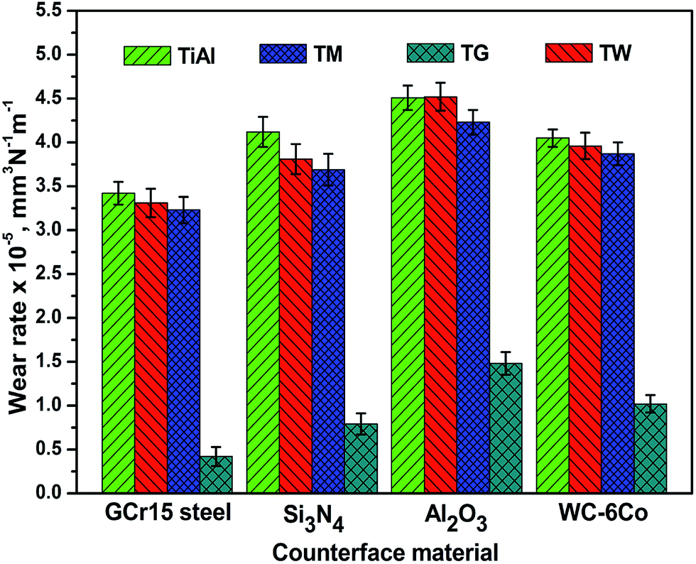
Fig. 5 and 6 respectively display the variations of friction coefficients and wear rates of TMSC vs. different counterface materials. It can be observed from Fig. 5 and 6 that wear and friction behaviors of TMSC are dependent on the counterface materials. Specifically, TMSC vs. Si3N4 and TMSC vs. WC-6Co have similar values, which are lower friction coefficients and wear rates than those of TMSC vs. Al2O3; TMSC vs. Al2O3 have the highest friction coefficients and wear rates; TMSC vs. GCr15 steel have the lowest friction coefficients and wear rates. In addition, it can be also observed from Fig. 5 and 6 that a reduction in friction coefficients and wear rates is presented after adding WS2, MoO3 and MLG. For all the four types of counterface materials, the friction coefficients and wear rates of TG are apparently lower than those of TM, which are medium friction coefficients and wear rates; in contrast, TW has the highest friction coefficients and wear rates. As is seen in Fig. 5, when sliding against GCr15 steel, Si3N4, Al2O3 and WC-6Co, TW are respectively subject to 32.07%, 28.57%, 32.84% and 29.31% reductions in friction coefficients; in the case of TM, 35.85%, 30.36%, 40.29% and 32.76% reductions in friction coefficients are respectively observed; and TG are respectively inclined to 39.62%, 35.71%, 37.31% and 32.76% reductions in friction coefficients. Regarding the wear rates, when sliding against GCr15 steel, Si3N4, Al2O3 and WC-6Co, WS2 respectively reduces the specific wear rates of TMSC by 3.22%, 6.07%, 0.67% and 1.49%; MoO3 respectively decreases the specific wear rates of TMSC by 5.56%, 10.44%, 6.21% and 3.73%; and MLG respectively reduces the specific wear rates of TMSC by 89.16%, 81.79%, 67.63% and 76.87%, as is shown in Fig. 6.
 |
| | Fig. 5 Variations of friction coefficients of TMSC vs. different counterface materials. | |
 |
| | Fig. 6 Variations of wear rates of TMSC vs. different counterface materials. | |
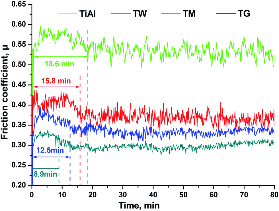
Based on the above results, from a tribological point of view, it can be deduced that: (i) TMSC vs. GCr15 steel may be the desirable design due to the excellently wear and friction behaviour; (ii) WS2, MoO3 and MLG indeed possess different lubrication effects; (iii) WS2 has a worse lubrication effect than MoO3, while MLG has the best lubrication effect. It is well recognized that friction coefficient curve as a function of time can obviously reflect the effect of addition of solid lubricant which can help in stabilizing the response by forming a solid lubricant-rich film on the worn surface during the friction process. Herein, Fig. 7 displays the friction coefficient curves of TMSC vs. GCr15 steel as a function of time, revealing that the variation trend of friction coefficients with sliding time can be divided into two different stages. It can be seen that friction coefficients are high at the initial stage, and then friction coefficients are found to approach steady-state values which exhibit lower friction coefficients. A comparison of the four curves indicates that the time for reaching steady-state values for TW, TM and TG is significantly shorter than that of TiAl and gradually reduced. Meanwhile, the fluctuation amplitudes also gradually decrease for TW, TM and TG. This further confirms that MoO3 has a better lubrication effect than WS2, while MLG has the best lubrication effect. In order to acquire deep insights on the respective lubrication effects of WS2, MoO3 and MLG, the worn surfaces of TMSC vs. GCr15 steel are analyzed in following section.
 |
| | Fig. 7 Friction coefficient curves of TMSC vs. GCr15 steel as a function of time. | |
3.3. Worn surface analysis
EPMA micrographs of worn surfaces of TMSC after tests are presented in Fig. 8, clearly indicating that the micrographs of worn surfaces of TW, TM and TG are distinct from that of TiAl. Fig. 8(a) is evident that TiAl exhibit rough worn surface and broad surface damages in forms of severe delamination and abrasive grooves, revealing that TiAl have load carrying capacity to a low extent. It can be responsible for the high friction coefficient, wear rate and fluctuation amplitude of as given in Fig. 5, 6 and 7. Such grooves are caused by shearing action of hard surface protuberance of GCr15 steel counterface ball (9.0 GPa) to the soft surface of TiAl (5.4 GPa) during the friction process. However, as seen in Fig. 8(b–d), no such severe abrasive grooves and delamination can be seen on the relatively smooth worn surfaces of TW, TM and TG, and the damage degrees of worn surfaces gradually decreases. It coincides with the aforementioned variation trends in friction coefficients and wear rates as presented in Fig. 5, 6 and 7. In addition, it is also notable that the worn surfaces of TW, TM and TG are covered by discontinuous island-like solid lubricant-rich films with different compactedness as suggested by EDS analysis (see in Table 2), as this is further confirmed by FESEM and Raman spectroscopy carried out on worn surfaces of TW, TM and TG (see in Fig. 10). These solid lubricant-rich films can effectively decrease the direct contacting area between TMSC-GCr15 steel counterface ball and provide the low shear strength junctions at the interface and the high wear resistance of TMSC, thus playing an important role in decreasing the friction coefficients and wear rates.21,22
 |
| | Fig. 8 EPMA micrographs of worn surfaces of TMSC after tests: (a) TiAl; (b) TW; (c) TM; (d) TG. | |
Table 2 Average element composition of worn surfaces of TMSC obtained by EDS
| Samples |
Element (at%) |
| O |
Al |
Ti |
Nb |
Cr |
B |
C |
W |
S |
Mo |
| TiAl |
10.8 |
39.8 |
46.3 |
1.5 |
1.2 |
0.4 |
— |
— |
— |
— |
| TW |
6.5 |
31.2 |
34.9 |
1.2 |
0.8 |
0.6 |
— |
9.3 |
15.5 |
— |
| TM |
22.9 |
29.7 |
36.9 |
0.8 |
0.6 |
0.5 |
— |
— |
— |
8.6 |
| TG |
4.7 |
33.8 |
41.6 |
0.9 |
1.0 |
1.2 |
16.8 |
— |
— |
— |
 |
| | Fig. 9 AFM micrographs of worn surfaces of TMSC after tests: (a) TiAl; (b) TW; (c) TM; (d) TG. | |
 |
| | Fig. 10 FESEM micrographs and Raman spectra of worn surfaces of TMSC after tests: (a) TW; (b) TM; (c) TG. | |
To have more information about worn surfaces of TMSC after tests, the three-dimensional AFM surface height morphologies of worn surfaces are carried out and plotted in Fig. 9. The individual two-dimensional line scans presented in Fig. 9-insert are taken parallelly and vertically to the sliding direction to imprecisely characterize surface smoothness of the irregular worn surfaces with discontinuous films and numerous peaks and valleys. One can be observed that when compared with TiAl, TW, TM and TG present obviously better surface smoothness, as can be confirmed by Ra. Quantitative roughness analyses of worn surfaces samples “a”, “b”, “c” and “d” are performed by the equipment's software and Ra are respectively 3.769 μm, 1.912 μm, 1.435 μm and 0.936 μm. It can be also observed form Fig. 9 that solid lubricant-rich films with different compactedness exhibit on the worn surfaces of TW, which confirms the above EPMA analyses for Fig. 8.
The above EPMA and AFM analyses of worn surfaces suggest that solid lubricant-rich films smear on worn surfaces of TMSC but display different compactedness. We can attribute such a phenomenon to the fact that WS2, MoO3 and MLG possess different lubrication mechanisms. In order to obviously understand their respective lubrication mechanisms, detailed microscopic investigates of worn surfaces and cross-sections of worn surfaces of TW, TM and TG vs. GCr15 steel counterface ball after tests are further characterized by FESEM and respectively presented in Fig. 10 and 11. It can be clearly seen from Fig. 10(a) that island-like film smears on worn surface of TW. Fig. 10(b) presents the Raman spectrum of worn surface seen in Fig. 10(a), indicating that the island-like film is WS2-rich film.3 It can be attributed to the fact that part of WS2 can be squeezed out from the matrix and then vertically migrates to worn surface under the action of normal force and frictional force. Finally, WS2 migrated to worn surface gradually spreads and forms discontinuous island-like films mainly containing WS2 under cyclic stress in the process of subsequent friction.3 It is apparent from Fig. 10(c and e) that different size island-like patches randomly disperse and expose on worn surfaces of TM and TG. Fig. 10(d) and (f) respectively display the Raman spectra of worn surfaces seen in Fig. 10(c) and (e), suggesting that the different size island-like patches exposed on worn surfaces of TM and TG are respectively MoO3 and MLG.11 It is easy to understand that in the process of subsequent friction, part of solid lubricant exposed on worn surfaces under the repeated sliding contact stress can peel off and gradually fill in the interspaces of debris to form solid lubricant-rich films.23 Thus, we have reasons to believe that MoO3-rich films and MLG-rich films can form on worn surfaces of TM and TG, as is evident from Fig. 8(c) and (d). In order to further confirm the presence of solid lubricant-rich films on the top of worn surfaces of TMSC filled with solid lubricant, the subsurface analyses, as is given in Fig. 11, are carried out on worn surfaces of TW, TM and TG by cross-sectioning them vertically to the sliding direction. It can be obviously observed that WS2-rich films with a thickness of about 2 μm, MoO3-rich films with a thickness of about 500 nm and MLG-rich films with a thickness of about 350 nm respectively exhibit on the top of worn surfaces of TW, TM and TG. Meanwhile, it can be seen from Fig. 11(a), subsurface microcracks appear in WS2-rich films and mechanically mixed layer (MML) of TW. Under cyclic stress in the process of subsequent friction, these microcracks spread and intersect, resulting in detachment of sheet-like WS2-rich films and leaving behind delaminations on the worn surfaces, which is proved by Fig. 8(b). Hence, WS2-rich films with loose microstructure result in larger friction coefficients and wear rates when compared with MoO3-rich films and MLG-rich films. A comparison of cross-sections of worn surfaces of TM and TG indicates that MLG-rich films are comparatively more compact than MoO3-rich films. It is conceivable that MoO3-rich films can result in larger friction coefficients and wear rates than MLG-rich films.23 It can be responsible for the aforementioned variation trends in friction coefficients and wear rates for TMSC filled with solid lubricant as determined in Fig. 5, 6 and 7.
 |
| | Fig. 11 FESEM micrographs of cross-sections of worn surfaces of TMSC after tests: (a) TW; (b) TM; (c) TG. | |
From the aforementioned FESEM analyses, it can be concluded that the lubrication mechanisms of WS2, MoO3 and MLG for TMSC are not identical in a way. Their respective lubrication mechanisms during the whole friction process can be proposed to some extent. As produced observed in Fig. 4, WS2, MoO3 and MLG homogeneously distribute in TW, TM and TG, respectively. At the onset of friction process and under the applied contact stress, hard protrusions on GCr15 steel counterface ball surface penetrate into surfaces of TW, TM and TG and remove the softer substrate TiAl materials, thus resulting in the formation of rough worn surfaces. This supports the large fluctuations of friction coefficients of TW, TM and TG in the initial stage of friction process, as is confirmed in Fig. 7.
Under the sliding contact stress in the process of subsequent friction, part of WS2 embedded into TW matrix overcomes potential barrier and vertically migrates to sliding surface.3 WS2 is easier to be sheared along the basal plane of the crystalline structures due to its weaker interlayer bonding.7,8 Hence, WS2 migrated to worn surface gradually spreads out and combines with wear debris to form WS2-rich films on worn surface of TW in the repeated sliding process, as is evident from Fig. 8(b), 9(b), 10(a) and 11(a). In the case of TM, after the onset of the friction process, different size island-like MoO3 patches randomly exhibit on worn surface as seen in Fig. 10(c). Subsequently, part of MoO3 gradually peel off from sliding surface to fill in the interspaces of debris and finally form MoO3-rich films on worn surface of TM, as is displayed in Fig. 8(c), 9(c) and 11(b). Likewise, as observed in Fig. 10(e), MLG spreads out along the sliding direction and smears on the worn surface of TG in form of different size island-like plates after the onset of the friction process. Whereafter, part of MLG gradually becomes finer and finer in the friction process and fills in the interspaces of debris to form MLG-rich films on the worn surface of TG, as is seen in Fig. 8(d), 9(d) and 11(c).
WS2-rich films, MoO3-rich films and MLG-rich films on worn surfaces of TW, TM and TG can effectively reduce the direct contacting area between composites and GCr15 steel counterface ball and provide low shear strength junctions at the interface and high wear resistance of TW, TM and TG,21,22 thus playing an important role in reducing friction coefficients and wear rates as determined in Fig. 5, 6 and 7. Since it is conceivable that the well worn surfaces with smooth and comparatively compact films could result in lower friction coefficients and wear rates, while the bad worn surfaces with rough and loose films could result in higher friction coefficients and wear rates.23 Hence, EPMA AFM and FESEM results considered together can explain that the friction coefficients and wear rates for TiAl, TW, TM and TG gradually decrease, coinciding with the above-mentioned variation trends in friction coefficients and wear rates as seen in Fig. 5, 6 and 7.
4. Conclusions
In order to well understand the respective lubrication effects and mechanisms of WS2, MoO3 and MLG, comparative studies of wear and friction behaviours of TMSC are carried out under different counterface materials in the present work. Wear and friction results present that for all the four types of counterface materials, the incorporation of WS2, MoO3 or MLG remarkably improves wear and friction properties of TMSC. Specifically, TM have lower friction coefficients and wear rates than TW, while TG have the lowest friction coefficients and wear rates. It obviously suggests that WS2, MoO3 and MLG possess different lubrication effects, while the lubrication effect of MLG is far superior to those WS2 of and MoO3. EPMA, AFM and FESEM analyses of worn surfaces of TW, TM and TG display the significant differences in worn surfaces with discontinuous island-like solid lubricant-rich films. The worn surface of TM exhibits lighter damage and comparatively more compact films than that of TW; in contrast, the worn surface of TG exhibits the lightest damage and the most compact films. It strictly means that WS2, MoO3 and MLG possess different lubrication mechanisms. In short, the present work demonstrates that WS2, MoO3 and MLG possess their respective lubrication effects and mechanisms. In addition, the present work also provides valuable information to acquire deep insights in understanding the lubricative properties of lamellar solid lubricants, as well as to enrich the lubrication theories of composites reinforced by solid lubricants.
Acknowledgements
This work was supported by the National Natural Science Foundation of China (no. 51210008); and the Fundamental Research Funds for the Central Universities (no. 2015-yb-008).
References
- B. M. Chen, Q. L. Bi, J. Yang, Y. Q. Xia and J. C. Hao, Tribol. Int., 2008, 41, 1145 CrossRef CAS.
- S. Y. Zhu, Q. L. Bi, J. Yang and W. M. Liu, Tribol. Int., 2011, 44, 1182 CrossRef CAS.
- Z. S. Xu, Q. X. Zhang and W. Z. Zhai, RSC Adv., 2015, 5, 45044 RSC.
- R. Tyagi, D. S. Xiong, J. L. Li and J. H. Dai, Tribol. Lett., 2010, 40, 181 CrossRef CAS.
- S. Y. Zhu, Q. L. Bi, M. Y. Niu, J. Yang and W. M. Liu, Wear, 2012, 274–275, 423 CrossRef CAS.
- X. L. Shi, Z. S. Xu, M. Wang, W. Z. Zhai, J. Yao, S. Y. Song and Q. X. Zhang, Wear, 2013, 303, 486 CrossRef CAS.
- M. Ratoi, V. B. Niste, J. Walker and J. Zekonyte, Tribol. Lett., 2013, 52, 81 CrossRef CAS.
- S. S. Xu, X. M. Gao, M. Hu, D. Jiang, F. Zhou, W. M. Liu and L. J. Weng, Appl. Surf. Sci., 2014, 288, 15 CrossRef CAS.
- A. K. Geim and K. S. Novoselov, Nat. Mater., 2007, 6, 183 CrossRef CAS PubMed.
- C. Lee, X. D. Wei, J. W. Kysar and J. Hone, Science, 2008, 321, 385 CrossRef CAS PubMed.
- Z. S. Xu, X. L. Shi, W. Z. Zhai, J. Yao, S. Y. Song and Q. X. Zhang, Carbon, 2014, 67, 168 CrossRef CAS.
- K. Yang, X. L. Shi, W. Z. Zhai and A. M. M. Ibrahim, RSC Adv., 2015, 5, 67102 RSC.
- K. Yang, X. L. Shi, W. Z. Zhai, L. Chen, A. Zhang and Q. X. Zhang, RSC Adv., 2015, 5, 44618 RSC.
- F. Wang and W. Ueda, Chem.–Eur. J., 2009, 15, 742 CrossRef CAS PubMed.
- J. N. Yao, K. Hashimoto and A. Fujishima, Nature, 1992, 355, 624 CrossRef CAS.
- W. Z. Zhai, X. L. Shi, Z. S. Xu, J. Yao, S. Y. Song and Q. X. Zhang, Wear, 2013, 310, 33 CrossRef.
- Q. S. Zhu, X. L. Shi, W. Z. Zhai, J. Yao, Z. S. Xu, S. Y. Song and L. Chen, Tribol. Lett., 2014, 55, 343 CrossRef CAS.
- J. Cheng, Y. Yu, L. C. Fu, F. Li, Z. H. Qiao, J. S. Li, J. Yang and W. M. Liu, Tribol. Int., 2013, 62, 91 CrossRef CAS.
- J. Cheng, Y. Yu, X. H. Zhang, H. Zhong, J. Q. Ma, F. Li, Q. L. Bi, J. S. Li and W. M. Liu, Intermetallics, 2012, 31, 121 CrossRef.
- Z. S. Xu, X. L. Shi, W. Z. Zhai, M. Wang, J. Yao and Q. X. Zhang, Tribol. Lett., 2014, 53, 617 CrossRef CAS.
- F. H. Stott, D. S. Lin and G. C. Wood, Corros. Sci., 2010, 13, 449 CrossRef.
- R. Tyagi, S. K. Nath and S. Ray, Metall. Mater. Trans. A, 2010, 33, 3479 CrossRef.
- Z. S. Xu, Q. X. Zhang, X. L. Shi and W. Z. Zhai, J. Mater. Eng. Perform., 2015, 24, 1925 Search PubMed.
|
| This journal is © The Royal Society of Chemistry 2015 |
Click here to see how this site uses Cookies. View our privacy policy here.