Hyun Young Jung‡
*a,
Sanghyun Hong‡b,
Ami Yub,
Sung Mi Jungc,
Sun Kyoung Jeoungd and
Yung Joon Jung*b
aDepartment of Energy Engineering, Gyeongnam National University of Science and Technology, Jinju, Gyeongnam 660-758, South Korea. E-mail: hyjung@gntech.ac.kr
bGeorge J. Kostas Research Institute for Homeland Security and Department of Mechanical and Industrial Engineering, Northeastern University, Boston, MA 02115, USA. E-mail: jungy@coe.neu.edu
cDepartment of Electrical Engineering and Computer Science, Massachusetts Institute of Technology, Cambridge, MA 02139, USA
dAutomotive Materials Convergence & System R&D Division, Korea Automotive Technology Institute, Chonan, Chungnam 330-912, South Korea
First published on 28th July 2015
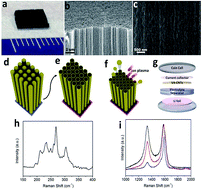
Herein, we report the use of vertically aligned carbon nanotubes (VA-CNTs) with controlled structure and morphology as an anode material for lithium-ion batteries. The tailored surface structure and open-end morphology of VA-CNTs made by ion milling and transfer processes increases the accessibility of Li ions, and allows Li ions to diffuse inside as well as on the surface of the CNTs through the generated surface defects, leading to the significantly improved lithium ion storage capacity compared to as-grown close-end VA-CNTs. The irreversible discharge capacity of the modified VA-CNTs anode reaches up to 2350 mA h g−1 at 2 C in the first cycle and the reversible capacity is in the range of 1200–557 mA h g−1 for the 2nd–20th cycles. The second insertion capacity of the modified CNTs electrode was 4 times higher than that of the as-grown CNTs and 3.2 times higher than that of a previously reported CNTs electrode for a commercial graphite device.
Recently, there has been a continuous global effort to increase the capacity and improve the lifespan of lithium-ion cells.8–14 Among the possible candidates to do this, carbon nanotubes (CNTs) have been widely studied as an electrode material for LIBs because their unique structure and properties such as large surface area, shorter Li-conduction distance, high electrical conductivity and tensile strength make them well suited as a critical component in novel anode materials for enhanced lithium storage.15,16 The capacity of CNTs results from the intercalation of Li ions between the graphite layers and in the interstitial sites of the close-packed CNT bundles.17 Overall, the theoretical calculations suggest that reversible capacities exceeding a LiC2 stoichiometry (>1116 mA h g−1) is attainable for CNTs,18 which represents a dramatic improvement over the limits of conventional graphite. The reported reversible capacity of CNTs ranges from 300 to 1000 mA h g−1,19 which is strongly linked to their different morphologies. In particular, vertically aligned CNTs (VA-CNTs) are an ideal candidate to improve the electrochemical performance due to their effective diffusion into the stable sites located on the nanotube surface or inside individual nanotubes.20–23
Herein, we report the electrochemical properties of VA-CNTs, whose structure and morphology were engineered through ion milling and nanotube film transfer processes for lithium-ion battery negative electrodes, with the aim to obtain a high lithiation capability and better overall performance. The present study was also undertaken to understand the influence of morphological features and defects on the electrochemical performance. Our surface defect-induced open-end VA-CNTs anode has three notable features for its use as the effective electrode material in a lithium-ion battery. First, Li-ion diffusion into the interior of the VA-CNTs through the opened ends and sidewall defects, which were generated by ion-milling and nanotube transfer process, can shorten the diffusion length of the redox couple and provide rapid electron transport because the energy barrier for Li diffusion through the defects is decreased.24 Second, the alignment of the VA-CNTs in the direction of ion diffusion and their optimized length obtained by controlling the CVD time significantly increases the accessibility of the electrode interior to the electrolyte. Finally, the increased active sites for electrochemical Li insertion/extraction dramatically improves the electrochemical performance. As a result, the lithium ion storage capacity of the nanotubes treated by the ion milling process is shown to be significantly improved when compared to the non-treated case.
Fig. 1a–c show the optical and scanning electron microscopy (SEM) images of the top- and side-view of the as-synthesized CNTs forest. The CNTs are microscopically well aligned with a wavy nanostructure. The network nanostructure is periodically rippled due to the intrinsic defects and bundling in the nanotubes and it is also interconnected with an average inter-bundle spacing of r ≈ 10 nm, thus providing highly dense and large area nanostructured networks for energy storage electrodes. By controlling the growth time during the CVD process, we first optimized the length of the CNTs at 100 μm for the effective diffusion of Li ions, which is an important factor to determine battery behavior. Fig. 1d–g are schematics showing the fabrication process of the battery devices using the VA-CNTs anodes. As shown in Fig. 1e, the as-grown CNTs forest (Fig. 1d) is transferred upside down to the copper substrate with the carbon adhesive layer on the surface. It should be noted that the top section of the as-grown nanotubes has a single-walled nanotube structure with a closed cap, while the bottom section, which is the surface of the transferred electrode (Fig. 1e), has a relatively open ended structure.25 When used as a battery electrode, Li ions can rapidly diffuse through the opened ends of the VA-CNTs. In Fig. 1h, a Raman spectrum of the VA-CNTs was obtained with a red laser with a wavelength of 785 nm. The peaks corresponding to the radial breathing mode (RBM) are typically observed between 150 and 350 cm−1 for single-walled CNTs. The corresponding diameters of the nanotube resonating at these frequencies are 1.1 nm to 0.86 nm. In the Raman spectra obtained using a wavelength of 532 nm, as shown in Fig. 1i, prominent features at 1330 cm−1 are indicative of the disorder (D) peak usually assigned to the K-point phonons of the typical A1g symmetry in polycrystalline graphite, and the peak at 1584 cm−1 (G peak) is common in single graphite crystals and is attributed to the zone centered phonons with E22g symmetry.26 The bottom-side of the VA-CNTs (or the top of Fig. 1e) have a defective tip, as shown by the higher D band intensity (ID/IG = 0.64, red solid line in Fig. 1i), where the D/G intensity ratio of the top surface of the as-grown CNTs was 0.26 (blue solid line in Fig. 1i). To increase the number of reactive sites for electrochemical lithium insertion/extraction, we have treated the VA-CNTs using Ar ion milling (Fig. 1f). The D to G band intensity ratio of the treated VA-CNTs in the Raman spectrum was increased to 0.97 (black solid line in Fig. 1i). For the electrochemical battery performance, half cells were assembled using a lithium film as the cathode and VA-CNTs as the anode, which were separated by a polymer membrane soaked in a liquid electrolyte solution consisting of 1.0 M lithium hexafluorophosphate (LiPF6) in ethylene carbonate (EC)/dimethyl carbonate (DMC) (Fig. 1g).
Fig. 2 shows the SEM and transmission electron microscopy (TEM) images of the as-grown close-end VA-CNTs, open-end VA-CNTs and artificially modified VA-CNTs. The top section of the as-grown nanotubes (Fig. 1d and 2a) has a clear single-walled CNT structure with a closed cap, as shown in Fig. 2b, while the transferred CNTs forest (Fig. 1e and 2c) has an open-end structure, as shown in Fig. 2d. Moreover, Fig. 2f verifies that the modified CNTs have a defective tip and surface, which corresponds to the Raman measurements shown in Fig. 1i.
![]() | ||
Fig. 2 Top surface SEM (a, c and e) and TEM (b, d and f) images of the (a and b) as-grown closed end, (c and d) open-ended and (e and f) modified open-end VA-CNTs. |
Fig. 3a and b show the results of first and second discharge/charge curves in a galvanostatic mode between 0.2 and 2.8 V at 2 C for the as-grown CNTs with a length of 500 μm and open-end CNTs electrode with the optimized length of 100 μm. The first cycle in both CNT electrodes exhibits a plateau in the voltage range between 0.6 and 0.9 V, which is designated by the yellow-shaded region in Fig. 3a. Such a plateau is found in most graphite or CNTs-based anodes, which originate from the reduction of the electrolyte and the formation of a solid electrolyte interface (SEI) layer on the surface of the electrodes.27 The capacity of the open-ended CNTs (red solid lines) is larger than that found for the as-grown, closed-cap CNTs (blue solid lines). This is because the alignment of the short nanotubes in the direction of ion diffusion allows Li ions to more readily access the open nanotube ends, and the surface sites inside and outside the tube offers additional reversible sites for intercalations. Furthermore, once inserted, the lithium ions undergo one-dimensional random walks both inside and outside the tube, and the relatively short CNTs allow ions to freely enter and exit. During the first reduction for the open-ended CNTs, a large irreversible capacity of 1980 mA h g−1 was observed, while a reversible capacity of 607 mA h g−1 was obtained from the first oxidation. After the formation of SEI in the first cycle, the plateau region vanishes for the second cycle, which clearly indicates that the irreversible process of SEI formation has been completed, leading to a stable electrolyte–electrode interface.
![]() | ||
Fig. 3 The first and second discharge (a) and charge (b) curves in galvanostatic mode between 0.2 and 2.8 V at 2 C for the closed-cap CNTs (blue solid line) and open-ended CNTs (red solid line). |
The specific capacities of the open-ended VA-CNTs as function of the cycle number are shown in Fig. 4a and b. The second insertion capacity of the open-ended CNTs electrode is 920 mA h g−1 but the capacity decreases with the increasing number of charge/discharge cycles. The coulombic efficiency shown in Fig. 4b, a ratio of extraction capacity to the insertion capacity expressed as percentage, reached 98% after the 20th cycle. To characterize the evolution of the kinetic parameters, especially the transport of Li ions within the open-ended CNT electrodes, electrochemical impedance spectroscopy (EIS) was performed (Fig. 4c). The ac impedance spectroscopy was carried out by applying a sine wave of 5 mV amplitude over a frequency range from 100 kHz to 0.01 Hz. EIS graphs show one depressed semi-circle in the high and intermediate frequency region, which generally corresponds to lithium-ion migration within the SEI layer and the charge transfer through the electrode/electrolyte interface. The 45° line in the low-frequency region shows the typical characteristics of the Warburg impedance,28 which generally reflects the diffusion process of Li within the bulk electrode. A comparison of the EIS Nyquist complex plots shows that the size of the semi-circle drastically decreases after the 2nd discharge cycle. This is because the passive film on the anode surface is destroyed by the de-intercalation of lithium ions from the anode; thus, the charge-transfer resistance decreases very rapidly.
In addition to the open-ended structure of the CNTs, the defects on the nanotube surface can facilitate better electrochemical performance24 because the presence of more defects can provide more available sites for Li ion insertion into the CNTs structure and shorter diffusion distance. Vacancy-type defects created by an Ar ion milling treatment can be considered as holes on the cylinder of graphene sheets. The presence of these holes allows lithium to better diffuse into and intercalate inside the CNTs (Fig. 5a), resulting in higher irreversible and reversible capacities in the modified CNTs compared to the open-ended CNTs. Fig. 5b shows the cyclovoltammetry (CV) curves of the open-ended and modified CNT electrodes in a coin cell at a scan rate of 1 mV s−1. The modified open-ended CNTs show considerably larger current densities during charge and discharge than the open-ended CNTs. In the first cycle, an irreversible reduction was observed from the potential around 0.85 V in the cathodic region. This peak is attributed to the decomposition of the solvent and the formation of SEI on the surface of the CNT electrodes. However, the irreversible reduction almost disappeared after the second cycle, which indicates that the carbon surface was passivated during the first cycle. The cathodic peak at 0 V is associated with Li intercalation, and its current density decreased gradually upon increasing the number of cycles to 20. The anodic band at 0.25 V is attributed to the de-intercalation of Li stored in sites other than the carbon layers. This anodic peak was particularly noticeable in the modified CNTs (Fig. 5d), indicating Li ions insertion into the defect sites residing in the modified CNTs. From 20 to 100 cycles, the CV curves were repeated at the same voltage ranges (Fig. 5c and d). These CV results were correlated with the formation of stage structures of Li–graphite intercalation compounds.
Fig. 6a exhibits the results of the first and second discharge/charge curves for the modified open-ended VA-CNTs electrodes. The introduction of defects into the CNTs shows a further improved reversible capacity as well as irreversible capacity. During the first reduction, a very large irreversible capacity of 2350 mA h g−1 was observed, while a reversible capacity of 832 mA h g−1 was obtained from the first oxidation. A high irreversible capacity means that the lithium ions are essentially consumed in the first cycle and that the larger amount of defects also causes a larger amount of lithium ions that are stored in the initial charge cycle to be permanently lost. The second insertion capacity of the modified CNTs electrode was 1200 mA h g−1, which was 1.3 times higher than that of the open-ended CNTs and 3.2 times higher than that of the commercial graphite electrode. To understand the capacity stability, the electrodes were subjected to 20 charge/discharge cycles (Fig. 6b and c). The modified CNTs electrodes approached a stable capacity with a coulombic efficiency of 97% after the 8th cycle of charge/discharge operations (Fig. 6c). The capacity gradually decreased with increasing number of charge/discharge cycles to 557 mA h g−1 after the 20th cycle (Fig. 6b and c), which is still higher than that found for graphite. Fig. 6d shows the rate capability of the modified CNTs anodes. The reversible capacity of the electrode was around 290, 205, 215, and 405 mA h g−1 for cycling rates of 4 C, 6 C, 5.5 C, and 3 C, respectively. This indicates that the performance of the modified CNTs at high rates was significantly stable by 100th cycle.
Electrochemical coin cells (half-cells) were assembled using lithium metal and VA-CNTs as the electrodes. Lithium metal foil (99.9%, Alfa Aesar) was used as the cathode. The electrodes were separated by a Celgard 2500 battery membrane that was soaked in a liquid electrolyte solution consisting of 1.0 M lithium hexafluorophosphate (LiPF6) in ethylene carbonate (EC)/dimethyl carbonate (DMC) (1:
1, volume ratio) (Aldrich) solution. CR2032 coin cells were assembled in an argon-filled glove box, where both oxygen and moisture content were maintained below 0.1 ppm.
Electrochemical characterization and electrochemical impedance spectroscopy (EIS) for the anodic materials were carried out using a potentiostat at room temperature. The cells were galvanostatically charged and discharged with cut-off potentials of 2.8 and 0.2 V. Cycling rates were calculated based on the theoretical capacity of graphite, and 1 C corresponded to a specific current of 372 mA g−1 for the active materials. Before each EIS measurement, the cell was held at the designated potential until the current decreased below 0.372 mA g−1. The amplitude of the AC signal applied to the electrodes was 5 mV and the frequency was varied from 100 kHz to 0.01 Hz.
Footnotes |
† Electronic supplementary information (ESI) available. See DOI: 10.1039/c5ra14263f |
‡ Authors equally contributed. |
This journal is © The Royal Society of Chemistry 2015 |