Xiaoyun Xu,
Mengru Han,
Jingyun Ma,
Chuanjiang Zhang and
Guangda Li*
Key Laboratory of Processing and Testing Technology of Glass & Functional Ceramics of Shandong Province, School of Material Science and Engineering, Qilu University of Technology, Jinan, 250353, China. E-mail: ligd@qlu.edu.cn
First published on 18th August 2015
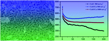
Nanoporous CuO/Cu composite materials with a bicontinuous structure are prepared by corroding a Cu–Al alloy. The obtained nanoporous CuO/Cu composites exhibit excellent performance as anodes for lithium ion batteries, which show a capacity of 600 mA h g−1 at a current density of 500 mA g−1 and maintain the capacity for 200 cycles and 445 mA h g−1 at 1000 mA g−1. The excellent electrochemical performance is attributed to the nanoporous and Cu-doped structure.
How to improve the conductivity of CuO is another key problem for improving battery performance. One way is to synthesize CuO/carbon composite materials, which can provide a better connection with metal oxide materials to form a homogenous composite or hybrid by interfacial interaction.24–27 Recently, some graphene based CuO nanocomposite electrode materials have been reported to enhance the storage capacity and cycling stability. For example, Rai et al. prepared CuO/graphene composite anode materials and exhibited reversible capacity of 516 mA h g−1 after 45 cycles.28 The other way is to prepared of CuO nanostructures supported on Cu substrate as integrated electrodes for anode materials.14,16 Zhang et al. reported CuO nanorods arrays on copper substrates as anode for LIBs. The unique structural features endower them excellent electrochemical performances as demonstrated by high capacities of 450–650 mA h g−1 at 0.5–2C.14
All of these techniques have been demonstrated as promising ways to designed CuO anode materials for LIBs. However, whether fabricated CuO/graphene composite or growth CuO on Cu substrate, the synthesis process is always very complex. Therefore, constructing novel nanostructure in favor of improving the battery performance and electronic conductivity are the main focus of our work.
It is well known that nanoporous materials are demonstrated to be an ideal structure for LIBs. A nanoporous structure means the active sites for Li+ ion storage are significantly increased. It becomes much easier for electrolyte and Li+ to enter and react with the active materials inside, resulting in a high specific capacity. In addition, the nanoporous structure can increase the interface contact area between the electrode and the electrolyte as well as the supply space for volume change during discharge/charge cycles, thus leading to enhance cycling performance.29,30
In this work, we propose a new approach to obtain CuO/Cu porous nanostructure by dealloy method. First, we prepared nanoporous Cu by using Cu–Al alloy. Through controlling anneal time and temperature, nanoporous CuO/Cu composite and pure CuO can be obtained, respectively. CuO/Cu composite was not prepared by mechanical mixing but growth together. The presence of Cu can greatly improve the electrical conductivity of the material. The electronic conductivity of Cu is 5.96 × 10⁷ S m−1, which is higher than carbon (2 × 10⁵ to 3 × 10⁵ S m−1) and amorphous carbon (1.25 × 10³ to 2 × 10³ S m−1).31 Not surprising, studies have shown that nanoporous CuO/Cu composite exhibited better rate performance and enhanced cycling life as anode materials. With an initial discharge capacity of 715.8 mA h g−1, thus-produced CuO/Cu anode can display a reversible discharge capacity of 600 mA h g−1 after 200 cycles at 500 mA g−1. Even at higher rates of 1000 mA g−1, their capacities can still stabilize at impressive values of 445.2 mA h g−1 after 200 cycles.
The X-ray powder diffraction (XRD) patterns were carried out on a Bruker D8 advanced X-ray diffractometer equipped with graphite monochromatized Cu Kα radiation (λ = 1.5418 Å). The morphologies of the samples were observed through field emission scanning electron microscopy (SEM) and transmission electron microscope (TEM) measurements, which were carried out on a JSM-7600F and a JEOL JEM 1011 TEM instrument, respectively. High-resolution transmission electron microscope (HRTEM) images were carried out on a JEOL 2010 transmission electron microscope with an accelerating voltage of 200 kV. The composition of the samples was analyzed by X-ray photoelectron spectra (XPS, VGESCALABMK X-ray spectrometer). Thermal gravimetric analysis (TGA) was carried out on a Mettler Toledo TGA/SDTA851 thermal analyzer apparatus under air atmosphere.
The electrochemical tests were performed under ambient temperature using two-electrode coin cell with Li foils serving as both the counter electrode and the reference electrode. The working electrodes was prepared by mixing 70 wt% active materials (CuO/Cu and CuO), 10 wt% sodium carboxy methyl cellulose (CMC), and 20 wt% acetylene black onto a copper foil substrate. The capacity of CuO/Cu was calculated by per grams of CuO. The electrodes were dried at 80 °C in a vacuum oven for 24 h. Celgard 2300 microporous polypropylene membrane was used as separator. The electrolyte consisted of a solution of 1 M LiPF6 in an ethylene carbonate/dimethyl carbonate/diethyl carbonate (EC/DMC/DEC, 1:
1
:
1, volume ratio). The cell assembly was carried out in an argon-filled glovebox with both the moisture and the oxygen content below 1 ppm. The discharge/charge tests of the samples were performed on a Land battery test system (CT2001A). The cyclic voltammetry (CV) test was carried out in the potential window of 0.01 V to 3.0 V by an electrochemical workstation (CHI 760e). The electrochemical impedance spectroscopy (EIS) was measured on an FRA-520 (MaterialsMates, Italia) connected to a Potentiostat-510 (MaterialsMates) in the frequency range from 100 kHz to 0.01 Hz.
![]() | ||
Fig. 1 XRD patterns of (a) nanoporous CuO/Cu composite and (b) CuO; XPS spectrum of (c) nanoporous CuO/Cu composite and (d) CuO. |
The nanoporous CuO/Cu composites and CuO are characterized by XPS. Cu2p3/2 spectra of samples before and after calcinations are resolved using Gaussian curve-fitting analysis and presented in Fig. 1c and d, respectively. Before calcinations, the main Cu2p3/2 peak exhibits two components. The one is located at 934.4 eV, which can be assigned to Cu2+ characteristic in the CuO phase. The other located at 932.9 eV can be identified as Cu0 characteristic of the pure Cu phase.32 Furthermore, the peaks at 941.1 and 943.3 eV are assigned to Cu2+ satellite peaks, indicating that CuO is the main component and a small quantity of Cu0 on the surface of the sample before calcinations. In contrast, the Cu2p3/2 peak in Fig. 1d exhibit only one peak located at 934.3 eV, along with two satellite peaks at 941.9 and 943.9 eV. The peak of Cu0 disappeared, suggesting the predominant existence of Cu2+ in CuO phase after a calcination treatment.
Typical TGA curves of the CuO/Cu under air atmosphere are shown in Fig. 2. The first weight loss is caused by removing of the water adsorbed on the surface of CuO/Cu. Loss of adsorbed water usually occur the temperature below 200 °C.33,34 The following weight increment between 180 and 400 °C is attributed to the transition of Cu to CuO. CuO can be obtained after the CuO/Cu calcined in air at 300 °C for 2 h. When the temperature exceed 400 °C, the conspicuous weight loss is due to the thermal decomposition of CuO into Cu2O and released O2 at the same time.35,36 According to the mass change of CuO/Cu, the content of Cu in nanocomposite can be calculated (10.26%).
Fig. 3a and b display SEM images of the as-prepared CuO/Cu, revealing the bicontinuous nanoporous structure. The width of the channels is about 20–30 nm. The nanoporous CuO/Cu structure can reduce the volume expansion and raise the conductivity of electrode. The novel CuO/Cu composite materials were prepared by corroding Cu–Al alloy, and the schematic illustration is exhibited in Fig. 3c. The HRTEM image in Fig. 3d and e reveal the CuO/Cu particle has a composite structure. The well-defined two regions are corresponding to CuO and Cu. The HRTEM image of CuO region (Fig. 3d) clearly displays the crystal planes (002) with a d-spacing of 0.250 nm and (−111) with a d-spacing of 0.248 nm. The lattice fringes of crystallized region of 0.208 nm shown in Fig. 3d can be assigned to (111) of Cu.
![]() | ||
Fig. 3 (a and b) SEM images of the nanoporous CuO/Cu; (c) schematic illustration of the formation of nanoporous CuO/Cu; (d and e) HRTEM images of the nanoporous CuO/Cu. |
Fig. 4a shows the CV curves of the CuO/Cu in the initial 5 cycles between 0 and 3.0 V at a scan rate of 0.1 mV s−1. The reduction peaks at 2.04, 1.45 and 0.80 V in the first discharge stage, indicate a multistep electrochemical process, including the formation of solid-solution phase of Cu1−xIICuxIO1−x/2, which converting into a Cu2O phase, and further to Cu.37–39 The peak at 1.13 V in the first cycle was attributed to the formation of solid electrolyte interface (SEI) films. In the following scans, the current peaks at 2.04 and 1.45 V shift to and maintained at higher potentials of 2.31 and 1.37 V. The potential shift to more positive potential in the next cycles is a common phenomenon for metal oxide anodes and attributed to the structure charges during the discharge/charge cycles. The three oxidation peaks in the charge stage (1.58, 2.54 and 2.78 V) are associated with the oxidation reaction from Cu to Cu2O and finally to CuO.39 In the subsequent CV cycle, the reduction and oxidation peaks maintain almost at the same potentials, indicating a high degree of reversibility of the redox reaction.
Fig. 4b shows the first discharge/charge curves of nanoporous CuO/Cu electrode at 100, 500 and 1000 mA g−1. The multiple plateaus in the charge curves demonstrate multiple reactions take place during the conversion reaction between CuO and Li. This process is consistent with the CV curves. The discharge/charge curves in the first cycle shows three obvious sloping potential ranges at 2.25–1.80, 1.40–1.00 and 1.00–0.02 V for the Li reaction. The first slope at 2.25–1.80 V indicates that Li react with CuO to form Cu1−xIICuxIO1−x/2. The second and third slopes are ascribed to the formation of Cu2O, and the followed conversion of Cu2O into Cu and Li2O. The initial discharge capacities of the porous CuO/Cu are measured to be 831.9, 715.8 and 670.5 mA h g−1 at 100, 500 and 1000 mA g−1, and the initial charge capacities are 657.1, 597.2 and 563.7 mA h g−1, which exhibited coulombic efficiency of about 79.0%, 83.4% and 84.1%, respectively. These results demonstrate that nanoporous CuO/Cu exhibit high capacity and excellent reversibility in the initial cycle. Fig. 4c exhibit the cycling performance of the CuO/Cu and CuO at 500 and 1000 mA g−1. After a few cycles, the CuO electrode showed a slightly capacity decrease while the CuO/Cu nanocomposite electrode showed a stable cycling performance during 200 cycles. The high reversible discharge capacity of 600 mA h g−1 were obtained, which decreased only 115 mA h g−1 comparing with the first capacity.
After treated at 300 °C for 2 h, the CuO/Cu oxidated and became CuO completely. The heat treatment can lead to a morphology change at the same time (Fig. 5). The nanoporous aggregated compactly, which can result in seriously volume affection during discharge/charge cycles. Therefore, the CuO exhibited only 300 mA h g−1 after 200 cycles at 500 mA g−1, which is much lower than that of CuO/Cu. At high current density of 1000 mA g−1, the superior reversible capacity of CuO/Cu are 445.2 mA h g−1 after 200 cycles, which is ∼66.4% of the first discharge capacity. The rate capability of the porous CuO/Cu is evaluated at different densities from 100 to 2000 mA g−1, as shown in Fig. 4d. The CuO/Cu anode shows an average discharge capacity of 570 mA h g−1 at 300 mA g−1, 511 mA h g−1 at 800 mA g−1, 460 mA h g−1 at 1000 mA g−1, and 420 mA h g−1 at 2000 mA g−1. The discharge capacity decreased slowly with increasing current density. The discharge capacity can still be recovered to 467 mA h g−1 when the density went back to 1000 mA g−1.
![]() | ||
Fig. 5 (a and b) SEM images of pure nanoporous CuO obtained by annealing at 300 °C for 2 h under atmosphere. |
The improved cycling performance and rate capability is mainly attributed to the unique features of porous CuO/Cu composite structure. The first and most important factor is that excellent conductivity of Cu embedded in CuO and formed CuO/Cu nanocomposite structure. The existence of Cu in CuO could improve the conductivity of CuO significantly. Second, the porosity structure ensures efficient electrolyte penetration and enhances the contact area between the electrode and electrolyte. Third, the nanoporous structure can efficiently alleviate volume variation during the discharge/charge process.
EIS considered as one of the most sensitive tools for the study of electrochemical behavior of electrodes. The Nyquist plots of the CuO/Cu and CuO electrode after 10 cycles are exhibited in the Fig. 6. The Nyquist plots are composed of the two semicircles overlapping each other in the high and middle frequency regions and inclined lines in the low frequency region, which are relative to the SEI resistance (Rs), charge transfer resistance (Rct) and the Warburg impedance of the Li+ ion diffusion in the solid materials, respectively.40 These impedance data (Table 1) are fitted to the equivalent circuit shown in Fig. 6 inset. The diffusion coefficient values of the Li+ ions for diffusion into the bulk electrode materials could be calculated by the following equation:41,42
D = 0.5(RT/AF2Cσ)2 |
Zre = RD + RL + σω−1/2 |
Samples | Re (Ω) | Rs (Ω) | Rct (Ω) | σ (Ω cm2 S−0.5) | DLi+ (cm2 S−1) |
---|---|---|---|---|---|
CuO/Cu | 9.2 | 6.1 | 35.7 | 36.2 | 2.7 × 10⁻¹⁴ |
CuO | 11.3 | 9.8 | 56.1 | 49.7 | 1.4 × 10⁻¹⁴ |
The parameters of the equivalent circuit and diffusion coefficients of the nanoporous CuO/Cu composite and CuO are calculated and recorded in Table 1. As shown in Fig. 6 and Table 1, the smaller diameter of the semicircle (CuO/Cu) than that of CuO electrode in the 10th cycle, revealing a low resistance of the CuO/Cu electrode. Furthermore, the Li+ diffusion coefficient of the CuO/Cu electrode increases, which suggests a high Li+ diffusion mobility in the CuO/Cu electrode that enhances its Li-storage performance. The nanoporous structure and metal Cu insertion can effectively facilitate electrolyte transport, shorten Li+ diffusion path and improve the Li+ diffusion within the CuO/Cu anodes. Therefore, these factors improve the cycling performance and rate capability of the batteries.
This journal is © The Royal Society of Chemistry 2015 |