DOI:
10.1039/C5RA14031E
(Paper)
RSC Adv., 2015,
5, 82960-82967
Elastomers uploaded electrospun nanofibrous membrane as solid state polymer electrolytes for lithium-ion batteries
Received
16th July 2015
, Accepted 15th September 2015
First published on 15th September 2015
Abstract
A new class of thin, safe and foldable solid composite electrolytes are produced by uploading 3-arm poly-(methoxy-poly(ethylene glycol) methacrylate) (3PEG) onto three different electrospun membranes, poly(vinylidene fluoride-co-hexafluoropropylene) (P(VdF-HFP)) membrane, 3PEG co-sprayed P(VdF-HFP) membrane (3PEG/PHP) and polyethylene terephthalate membrane (PET) and are named 3PEG@PHP, 3PEG@3PEG/PHP and 3PEG@PET, respectively. The electrospun membranes serve as a skeleton to enhance the mechanical strength of composite electrolytes, whereas 3PEG filled in the micropores of the matrix affords an ion transport carrier. Among these composite electrolytes, the one based on a PET electrospun membrane exhibited a high ionic conductivity of 5.9 × 10⁻⁴ S cm−1 at 100 °C because of it possessing the lowest shrinkage rate with high filling loading of 3PEG. The decomposition potential of the composite electrolytes is above 4.5 V at 100 °C. Successful charge and discharge cycling of 3PEG@PET based all solid state lithium ion battery have maintained the initial discharge capacity of 137.6 mA h g−1 at 0.1C, which proves that they are ideal candidates for all solid state rechargeable lithium ion batteries.
1. Introduction
Rechargeable lithium-ion batteries (LIBs), used in emerging electric vehicles and all types of portable electronics, have drawn world wide attention due to their high energy density, excellent cycle life and low self-discharge rate.1–3 Strong market demands have created the need for development of projected and advanced electrolytes for lithium-ion batteries.4 The commercial electrolytes of LIBs are usually liquid solutions mainly composed of carbonate solvents and lithium salt such as propylene carbonate (PC), diethyl carbonate (DEC), dimethyl carbonate (DMC) and ethylene carbonate (EC). Unfortunately, these solvents exhibit high vapor pressures at elevated temperatures (>60 °C), leading to a tendency of leakage and flammability. At the same time, batteries able to work at a relatively high temperature are needed for some specific applications such as petroleum exploration.5–8 Therefore, developing safe and efficient polymer electrolytes without any liquids, i.e. solid polymer electrolytes (SPEs), is urgently in demand.
To date, poly(ethylene oxide) (PEO) based electrolytes are widely studied because of their effective ion solvating properties, but their conductivities (about 10−7 S cm−1 at ambient temperature) are far below the level of ionic conductivity required for practical applications (10−3 S cm−1). Branched polymer electrolytes have been considered as one of the most promising candidates because they are intrinsically resistant to crystallization, which is advantageous in improving their conductivities. For example, branched PEO with a polyimide main chain and methoxy-poly(ethylene glycol) methacrylate side chains achieves a higher ionic conductivity (10−5 to 10−6 S cm−1) than linear PEO-based polymer at ambient temperature.9,10 Previous studies have reported the synthesis of 3-arm branched poly(poly-(ethylene glycol) methyl ether methacrylate) (3PEG) via atom transfer radical polymerization. It was noted that 3PEG has an amorphous state at room temperature due to the branched structure. This unique structural feature of 3PEG can provide enhanced ionic conductivity when employed as a polymer matrix for SPEs.11 However, the application of branched PEO-based polymers for commercial use is staggered due to their poor mechanical properties, especially at a high temperature. When the temperature increases beyond 100 °C, their fluidity leads to internal short-circuit failures between electrodes because of the low melting temperature of PEO-based polymer electrolyte.
One favorable solution to this problem involves the use of an electrospun matrix to isolate electronic flow between the cathode and anode to prevent physical contact in the inner of batteries by decreasing fluidity of the polymer electrolyte at high temperature as well as offsetting their poor mechanical properties. Electrospun membranes possess remarkable characteristics, such as a large surface-to-volume ratio, an abundant pore number as well as chemical compatibility with a Li electrode, among which P(VdF-HFP) and PET are especially preferred because of their high dielectric constant, good thermal, electrochemical stability and affinity for electrolytes.12–16
In this study, thin, deformable, safe and high-temperature-tolerant novel composite electrolytes are obtained by combining 3-arm branched poly-(methoxy-poly(ethylene glycol) methacrylate) (3PEG) with three electrospun matrices, including P(VdF-HFP) membrane, 3PEG cladding P(VdF-HFP) membrane (3PEG/PHP) and poly(ethylene terephthalate) membrane (PET). The porous substrates act as a mechanical framework, whereas 3PEG is the ion transport carrier. The composite electrolytes exhibit good thermal and mechanical properties, without impairing the advantageous features such as the high ionic conductivity of 3PEG. Electrochemical test results reveal that the operating temperature for the present composite electrolyte is up to 100 °C.
2. Experimental section
2.1 Materials
3PEG was synthesized by the method shown in our previous study.11 Poly(vinylidene fluoride-co-hexafluoropropylene) (P(VdF-HFP)), (Mn = 4 × 10⁵ g mol−1, Aldrich) and poly(ethylene terephthalate) (PET, inherent viscosity = 0.8 dl g−1, Yuanfang Co., Ltd Shanghai) were dried in a vacuum oven at 60 °C for 24 h before use. Lithium perchlorate (LiClO4) was dried in a vacuum oven and transferred to an argon-filled glove box with oxygen and a moisture level of <0.1 ppm. LiFePO4, PVdF binder, carbon black and lithium metal anode were chemically pure and purchased from Damao Chemicals, Tianjin, China. Trifluoroacetic acid, acetone, N,N-dimethylformamide, dichloromethane and acetonitrile were obtained from China Medicine Co., Ltd, and used as received.
2.2 Preparation of nanofibrous matrices
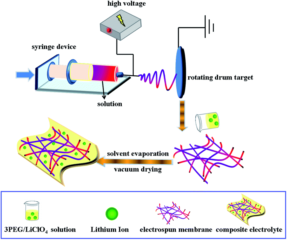
P(VdF-HFP) nanofibrous membranes were prepared by electrospinning. A 16 wt% solution of P(VdF-HFP) for electrospinning was prepared by dissolving P(VdF-HFP) in a mixture of acetone and N,N-dimethylformamide (DMF) (3/1, v/v) by mechanical stirring overnight. The solution was taken into the syringe and delivered with a flow rate of 1.2 ml h−1. Electrospinning progress was conducted at an electric voltage of 20 kV at room temperature with the abovementioned solution and the distance between the target drum and the syringe needle tip (inner diameter 22 μm) was 15 cm.
PET nanofibrous membranes were obtained similarly to P(VdF-HFP) nanofibrous membranes. A 10 wt% solution of PET dissolved in a mixture of trifluoroacetic acid (TFA) and dichloromethane (3/2, v/v) was electrospun at the applied voltage of 25 V at room temperature with a flow rate of 3 ml h−1. The grounded collector was located at a fixed distance of 15 cm from the needle tip.17
To ensure that the surface of each P(VdF-HFP) is coated with 3PEG, the 3PEG/PHP nanofibrous membranes were prepared by combining electrospinning with electrospraying. Two-needle electrospinning/electrospraying apparatuses were set up. P(VdF-HFP) solution was fed into a syringe pump with the same parameters used for electrospinning, whereas 3PEG solution (6 wt%, acetonitrile) in another syringe parallel to the former one was provided for spraying. Two needles were arrayed closely and parallel in the direction vertical to the axes of the rotating cylinder with the one for spray slightly higher than the other one, thus 3PEG coated P(VdF-HFP) nanofibers were formed, simultaneously. This method is analogous to coaxial electrospinning.18,19 Finally, three fabricated nanofibrous matrices were dried under vacuum at 60 °C for 24 h and used for characterization and further studies.
2.3 Preparation of composite electrolytes
A 3PEG and LiClO4 solution ([O]/Li+] ratio = 20) with predetermined amounts of 3PEG and LiClO4 dissolved in anhydrous acetonitrile was stirred for several hours to form a homogeneous solution. After immersing nanofibrous membranes (3PEG@PHP, 3PEG@3PEG/PHP and 3PEG@PET) into the mixture for 6 hours, the solvent-containing composite electrolyte films yielded. To obtain the designed composite electrolyte membranes, the as-prepared films were finally dried under vacuum at 45 °C for 24 h. The manufacturing processes are shown in Scheme 1.
 |
| | Scheme 1 Preparation process of foldable electrolyte membranes. | |
2.4 Coin cell assembly
LiFePO4/Li half cells were fabricated with 2025-coin type cells in the argon-filled glove box using the 3PEG@PET as electrolyte. LiFePO4 electrodes were prepared by mixing the LiFePO4 powder, carbon black and PVdF in the ratio of 80![[thin space (1/6-em)]](https://www.rsc.org/images/entities/char_2009.gif) :10:10 by wt in N-methylpyrrolidone (NMP) solvent. The mixed slurry was then coated onto aluminum foil and dried at 120 °C for 6 h. The cell assembly was carried out in an argon-filled glove box with a moisture level <10 ppm.
:10:10 by wt in N-methylpyrrolidone (NMP) solvent. The mixed slurry was then coated onto aluminum foil and dried at 120 °C for 6 h. The cell assembly was carried out in an argon-filled glove box with a moisture level <10 ppm.
2.5 Characterization
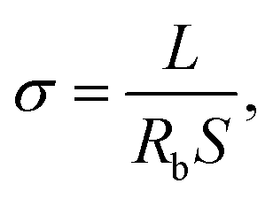
The morphology of the nanofibrous matrices and composite polymer electrolyte membranes were observed by scanning electron microscopy (SEM, FEI Quanta 200 SEM) operating at 20 kV. Thermal gravimetric analysis (TGA, Perkin-Elmer TGA 7) with the heating rate of 15 °C min−1 under a nitrogen atmosphere were used to measure the thermal degradation temperatures (Td). Glass transition temperatures (Tgs) were measured with a differential scanning calorimeter (DSC, TA instrument Q2000) at a heating rate of 10 °C min−1 under a nitrogen atmosphere. The Tgs of samples were obtained using the mid-point method on the second heating curve. The mechanical measurement of the composite electrolyte membranes was carried out on CMT-8000 mechanical testing apparatus (SANS Corp., Shenzhen, China) with a specimen width of 1.0 cm. The ionic conductivities of all the prepared composite polymer electrolyte were gauged by electrochemical impedance spectroscopy (EIS) using a Zahner Zennium electrochemical analyzer (Germany) with SPE sample membranes sandwiched between two stainless-steel (SS) electrodes and measured at an amplitude of 10 mV under the frequency of 1 Hz to 100 kHz. The samples were thermally equilibrated at each temperature for 30 minutes to ensure the precision of every test dot. Ionic conductivity of SPE can be calculated from eqn (1) as follows,| |
 | (1) |
where Rb represents the bulk resistance, L is the thickness and S stands for the area of the sample. The electrochemical stability of the samples was investigated by linear sweep voltammetry (LSV). All experiments were carried out at a sweep rate of 5 mV s−1 in the voltage range of 2.0–7.0 V (vs. Li+/Li) at 100 °C. Cycling performance tests of the Li/3PEG@PET/LiFePO4 cells were conducted in an automatic galvanostatic charge–discharge unit, Neware BTS (Shenzhen, China), over the range of 2.5–4 V at 80 °C and 100 °C.
3. Results and discussion
3.1 Morphological analysis and thermal behaviors
The 3PEG filled electrospun membranes were carried out in an anhydrous acetonitrile solution at room temperature. Digital images of 3PEG elastomer and composite electrolytes are shown in Fig. 1. Compared with the 3PEG elastomer, the macro morphology of 3PEG@PET with 3PEG directly filled in the PET electrospun substrate shows that the composite electrolyte membranes are deformable and remain constant, which can satisfy the application in foldable lithium-ion batteries. The images of P(VdF-HFP), 3PEG/PHP and PET nanofibrous membranes prepared by electrospinning are presented in Fig. 2. It can be observed that the P(VdF-HFP) and PET nanofibers were randomly dispersed in the membranes with an average fiber diameter and smooth surface. Though the 3PEG/PHP nanofibers have a relatively rough morphology and large diameter, the interconnected open pore structure of the 3PEG-clad electrospun membranes still remained unmodified (Fig. 2). Fig. 2D–F show the morphology of 3PEG@PHP, 3PEG@3PEG/PHP and 3PEG@PET. After immersing in the 3PEG and LiClO4 acetonitrile solution, 3PEG was filled into the micropores of the electrospun membranes. Among the three composite electrolytes, 3PEG@PHP showed least filling rate due to the poor compatibility with 3PEG. For the 3PEG coated on the surface of the nanofibers, the 3PEG@3PEG/PHP membrane possessed a more uniform surface without any micropores. The same was observed for 3PEG@PET, the micropores were filled with 3PEG completely. Fig. 3 presents the macro-morphology and shrinkage of three composite electrolytes based on different electrospun membranes by measuring the (area-based) dimensional change. The composite electrolytes based on P(VdF-HFP), 3PEG@PHP and 3PEG@3PEG/PHP show a large shrinkage and a rough surface, whereas the dimensional change of the 3PEG@ PET appears to be negligible. The results imply that the 3PEG@PET electrolyte exhibits good shape retention and flat surface. Thermal stability of the electrolytes was first evaluated by TGA (Fig. 4A). The weight loss occurred after 250 °C for all the composite electrolytes (3PEG@PHP, 3PEG@3PEG/PHP and 3PEG@PET), suggesting that the prepared electrolytes are stable up to 250 °C, which is high enough for use in lithium ion batteries. The thermal properties of the composite electrolytes doped with lithium salt are also determined by DSC (Fig. 4B) and samples are first heated to 150 °C to remove thermal history. The glass transition temperatures (Tgs) of all the electrolytes are far below room temperature, which means that the 3PEG chain shows good segment movement ability regardless of the filler effect in the electrospun membrane. The 3PEG@PHP electrolyte shows the highest Tg value, possibly due to the poor compatibility between P(VdF-HFP) and 3PEG, which inhibits the movement of the 3PEG segment.
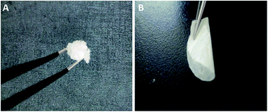 |
| | Fig. 1 Digital image of (A) 3PEG and (B) 3PEG@PET electrospun membrane. | |
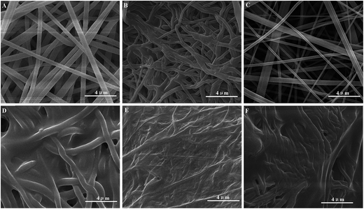 |
| | Fig. 2 SEM images of (A) P(VdF-HFP), (B) 3PEG/PHP, (C) PET, (D) 3PEG@PHP, (E) 3PEG@3PEG/PHP and (F) 3PEG@PET. | |
 |
| | Fig. 3 Images of composite electrolytes (A) before and (B) after being uploaded with 3PEG. | |
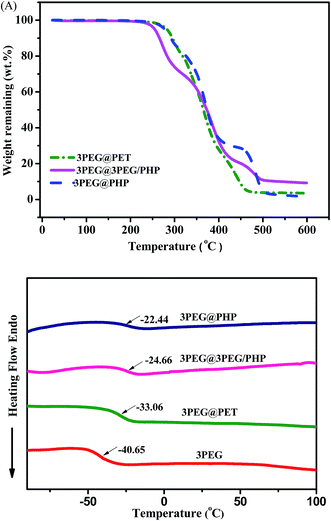 |
| | Fig. 4 (A) TGA curves of composite electrolytes with a heating rate of 15 °C min−1, (B) DSC thermograms of 3PEG and electrolytes obtained from second heating curves with a heating rate of 10 °C min−1. | |
3.2 Mechanical and electrochemical properties
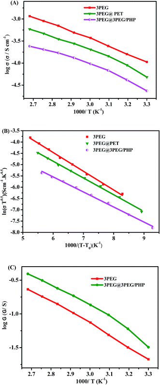
Impedance spectroscopy was employed to acquire the ionic conductivity of the electrolytes within the temperature ranging from 30 °C to 100 °C using an AC impedance analyzer with the composite polymer electrolytes sandwiched between a stainless steel blocking electrode. The ionic conductivities of electrolytes based on different thickness of the electrospun matrix are presented in Fig. 5. It can be seen that the ionic conductivity values reduce with the increase of thickness of the electrospun substrates, which is ascribed to the ionically nonconductivity of the electrospun nanofiber skeleton. Composite electrolyte membranes can hardly form independent films when the thickness of the substrates is decreased to 10 μm. A trade-off between ionic conductivity and mechanical properties must be made, so 20 μm is a good choice to achieve a win–win situation with composite electrolytes. The inset in Fig. 5 gives the typical stress–strain curves for 3PEG@3PEG/PHP and 3PEG@PET respectively. It can be seen that the tensile strength of 3PEG@3PEG/PHP is 6.0 MPa, with an elongation at break of 102% and the tensile strength of 3PEG@PET is 6.6 MPa, with an elongation at break of 83%. This result suggests that the as prepared composite electrolytes have considerable tensile strength and good elongation properties. The temperature dependent ionic conductivity of the composite electrolytes are also measured and compared with that of pure 3PEG electrolyte. Fig. 6A shows that the conductivities rise with the elevated temperature over a wide range of temperatures. The conductivity of the composite electrolytes follows the order: 3PEG@PET > 3PEG@3PEG/PHP > 3PEG@PHP both at ambient temperature and elevated temperature, which is the reverse order of Tg (Table 1). Because the ion conductivity occurs mainly through the amorphous region in the 3PEG matrix, the increase of the ionic conductivity for the composite polymer electrolytes mainly relates to the movement of the segment.20 3PEG@PET exhibits the highest conductivity value and this coincides with its significantly lower Tg (−32.06 °C). The low ionic conductivity of 3PEG@PHP electrolyte film should also be ascribed to the poor compatibility of the 3PEG with the P(VdF-HFP) matrix, resulting in a few 3PEG in the micropore of the nanofibrous membranes, which corresponds directly with that estimated by SEM imaging.21,22
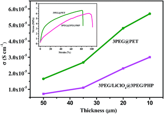 |
| | Fig. 5 Ionic conductivity of 3PEG@3PEG/PHP and 3PEG@PET dependent upon the thickness of electrospun membranes. Inset shows tensile tests of 3PEG@3PEG/PHP and 3PEG@PET. | |
 |
| | Fig. 6 Temperature dependence of (A) ionic conductivity of composite electrolytes, (B) their VTF regression curves and (C) ionic conductance curves. | |
Table 1 Ionic conductivity, Tg and activation energies of electrolytes
| Electrolytes |
Thickness (μm) |
σ (S cm−1) at 30 °C |
σ (S cm−1) at 100 °C |
G (S) at 30 °C |
G (S) at 100 °C |
Tg (°C) |
Ea (eV) |
| 3PEG |
100 |
1.1 × 10⁻⁴ |
1.2 × 10⁻³ |
0.021 |
0.23 |
−40.65 |
0.072 |
| 3PEG@PHP |
30 |
8.9 × 10⁻⁶ |
7.8 × 10⁻⁵ |
0.0059 |
0.052 |
−22.44 |
0.056 |
| 3PEG@3PEG/PHP |
30 |
2.3 × 10⁻⁵ |
2.4 × 10⁻⁴ |
0.016 |
0.16 |
−27.66 |
0.058 |
| 3PEG@PET |
30 |
4.8 × 10⁻⁵ |
5.9 × 10⁻⁴ |
0.032 |
0.39 |
−32.06 |
0.064 |
For a solid polymer electrolyte system, the temperature dependent ionic conductivity obeys the Vogel–Tamman–Fulcher (VTF) equation as follows,
| |
 | (2) |
where
σ is the ionic conductivity at different temperatures,
A is a frequency factor that often relates to the number and mobility of charge carriers, and
Ea is the activation energy,
R is the perfect gas constant,
T0 is the Vogel temperature at which relaxation times become infinite or the mobility of ions goes to zero. According to the literature,
T0 is 50 K below the glass transition temperature on polyether-based polymer electrolytes.
23 The VTF equation predicts that a plot of ln(
σT1/2)
vs. 1/(
T −
T0) should be linear, which is exactly observed in
Fig. 6B. The fitting results are listed in
Table 1.
Ea values of 3PEG and composite electrolytes vary from 0.056 eV to 0.072 eV, respectively, which are in agreement with the values for the amorphous state composite polymer electrolyte reported.
24–26 When considering polymer electrolytes acting as electrolyte as well as separator, ionic conductance normalized by sample thickness is more important in determining cell performance than ionic conductivity.
27 Due to the short ion diffusion channel, thin polymer electrolytes are advantageous in delivering high ionic conductance. Previous results (
Fig. 5) show that the electrospun matrix with the thickness of about 20 μm is the best choice taking both ionic conductivity and the morphology of the composite electrolytes into account. The thickness of the composite electrolytes, approximately 30 μm, is lower than 3PEG electrolyte (≈100 μm) (
Fig. 6C) highlighting the advantages of thin composite electrolytes on the ionic conductance. Contrary to the results of ionic conductivity, 3PEG@PET exhibits higher ionic conductance than pure 3PEG electrolyte. Ionic conductance was calculated by
eqn (3):
The higher ionic conductance of electrolytes has been proven to be beneficial for the circulation properties of the cell.28
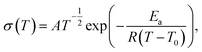
The characteristic EIS of 3PEG@PET at different temperatures from 30 °C to 100 °C are presented in Fig. 7. The Nyquist plot is a slanted line without a semicircle in the high-frequency region. This owes much to the low Tg of composite electrolytes, which ensure the segments excellent mobility and short relaxation time of the high-frequency response.29 The semicircle replaced by the inductive response below the real axis is another reasonable possibility.30
 |
| | Fig. 7 Impedance spectra of 3PEG@PET at different temperatures. | |
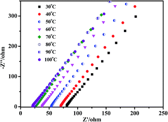
It is important to investigate the electrochemical stability of the electrolytes for practical battery applications within the operation voltage of the battery system. The electrochemical stability windows of 3PEG@3PEG/PHP and 3PEG@PET electrolytes were studied using linear sweep voltammetry with lithium foil as both the counter and reference electrodes. The decomposition voltage of the polymer electrolyte was determined by the steel as the working electrode at 100 °C. The results are shown in Fig. 8 in which the electrolyte was swept from 2 V to 7 V (versus Li/Li+) at a constant rate of 5 mV s−1. We notice that the electrochemical decomposition potentials of 3PEG@3PEG/PHP and 3PEG@PET are about 4.8 V and 4.9 V in the intersection of the line fitting the steep current increase and the voltage axis, respectively.31 3PEG was tightly trapping in the pores of the electrospun membrane contributing to the good oxidative stability of the composite electrolytes. Thus, this interaction will contribute to the high electrochemical stability window.32 This is similar to the value reported by Zhang et al.33 for the system PEO16–LiClO4–0 wt% MLA. Also Kang et al.34 found that the electrochemical stability seemed almost similar between the linear and multi-armed electrolyte. Good electrochemical stability of the electrolyte at elevated temperatures makes the electrolyte a potential candidate for lithium-ion batteries operating at a high voltage.
 |
| | Fig. 8 Linear sweep voltammetry curves of 3PEG/@3PEG/PHP and 3PEG@PET (scan rate: 5 mV s−1). | |
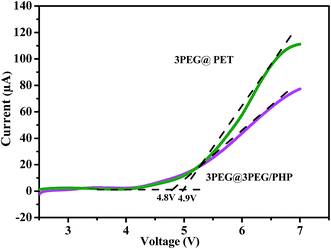
To evaluate the electrochemical performance of 3PEG@PET as electrolyte in lithium-cells, coin-type cells were fabricated with Li as the anode and LiFePO4 as the cathode. The assembled cells were subjected to cycle tests. A weak Faraday current can be observed between 4 V and the decomposition potential for the electrolyte. For safety considerations, 4 V was set as the cut-off voltage for Li/3PEG@PET/LiFePO4 battery cycling tests. The second charge–discharge profiles of Li/3PEG@PET/LiFePO4 cells at 80 °C and 100 °C are shown in Fig. 9A. Cells were cycled under a voltage range of 2.5–4 V at 0.1C. Higher temperature (100 °C) discharge capacity of the cell was 137.6 mA h g−1, which is significantly higher than that at 80 °C (123.5 mA h g−1). This is due to the advanced segment movement of solid-state electrolyte and increased Li-ion mobility in LiFePO4/FePO4 mixed phase at an elevated temperature.35 The constant potential region around 3.4 V versus Li/Li+ at 100 °C was observed for the charge–discharge curves, suggesting that reversible charge/discharge reactions proceeded. Fig. 9B presents the discharge capacity of Li/3PEG@PET/LiFePO4 upon cycling at 100 °C with a capacity retention exceeding 95.7 mA h g−1 for 50 cycles. The formation of a solid electrolyte interphase (SEI) and oxidizability of lithium perchlorate may be attributed to the capacity decrease, leading to the discharge capacity of the Li/3PEG@PET/LiFePO4 cell to a lower value than the theoretical specific capacity of LiFePO4 (about 170 mA h g−1).36 At high temperature, the passivation film may crack because of the deformation of the metallic lithium. Then, fresh lithium is exposed to the electrolyte again. Another reason contributing to the capacity fade may be the poor interface connection between the electrode and electrolyte. Searching for appropriate anode material or replacing lithium salt with more temperature stable ones may be a potential solution to this phenomenon, such as replacing metallic lithium with a lithium alloy and substituting lithium bis(trifluoromethanesulfonyl)imide (LiTFSI) or lithium bis(oxalate)borate (LiBOB) for lithium perchlorate.7,37 Interposing an additional thin film of an ion-conducting and electron-insulating oxide between electrode and electrolyte may help decrease the impedance and improve the compatibility of the interface to reduce the capacity fade.38
 |
| | Fig. 9 (A) Second charge/discharge curves at 80 °C and 100 °C and (B) cycling properties of Li/3PEG@PET/LiFePO4 at 100 °C (0.1C rate, 2.5–4 V). | |
4. Conclusions
Solid state polymer electrolytes that can fulfill the requirements of safety and flexibility have been successfully fabricated by combing a branched polymer with an electrospun matrix. Composite electrolytes based on PET possess better morphology, low shrinkage and the highest ionic conductivity. 3PEG@PET electrolytes show good thermal stability (250 °C), electrochemical stability (4.9 V) and high temperature discharge capacity (137.6 mA h g−1) at 0.1C. With liquid free and reversible charge/discharge reactions, the elastomer filled electrospun nanofibrous membrane can be a candidate for high performance safe lithium-ion batteries.
Acknowledgements
This study was financially supported by the National Natural Science Foundation of China (21404054) and the National Science Fund for Distinguished Young Scholars (51425304).
References
- M. Armand and J. M. Tarascon, Nature, 2008, 451, 652–657 CrossRef CAS PubMed.
- J. M. Tarascon and M. Armand, Nature, 2001, 414, 359–367 CrossRef CAS PubMed.
- B. Scrosati, J. Hassoun and Y. K. Sun, Energy Environ. Sci., 2011, 4, 3287–3295 CAS.
- B. Scrosati and J. Garche, J. Power Sources, 2010, 195, 2419–2430 CrossRef CAS PubMed.
- N. Takami, M. Sekino, T. Ohsaki, M. Kanda and M. Yamamoto, J. Power Sources, 2001, 97–98, 677–680 CrossRef CAS.
- B. Ravdel, K. M. Abraham, R. Gitzendanner, J. DiCarlo, B. Lucht and C. Campion, J. Power Sources, 2003, 119–121, 805–810 CrossRef CAS.
- K. Xu, Chem. Rev., 2004, 104, 4303–4417 CrossRef CAS.
- J. B. Goodenough and Y. Kim, Chem. Mater., 2010, 22, 587–603 CrossRef CAS.
- N. Yoshimoto, O. Shimamura, T. Nishimura, M. Egashira, M. Nishioka and M. Morita, Electrochem. Commun., 2009, 11, 481–483 CrossRef CAS PubMed.
- L. Ye, Z. G. Feng, Y. M. Zhao, F. Wu, S. Chen and G. Q. Wang, J. Polym. Sci., Part A: Polym. Chem., 2006, 44, 3650–3665 CrossRef CAS PubMed.
- Y. F. Tong, L. Chen, X. H. He and Y. W. Chen, J. Power Sources, 2014, 247, 786–793 CrossRef CAS PubMed.
- X. Li, G. Cheruvally, J. K. Kim, J. W. Choi, J. H. Ahn, K. W. Kim and H. J. Ahn, J. Power Sources, 2007, 167, 491–498 CrossRef CAS PubMed.
- J. R. Kim, S. W. Choi, S. M. Jo, W. S. Lee and B. C. Kim, J. Electrochem. Soc., 2005, 152, A295–A300 CrossRef CAS PubMed.
- G. Cheruvally, J. K. Kim, J. W. Choi, J. H. Ahn, Y. J. Shin, J. Manuel, P. Raghavan, K. W. Kim, H. J. Ahn, D. S. Choi and C. E. Song, J. Power Sources, 2007, 172, 863–869 CrossRef CAS PubMed.
- H. S. Jeong, J. H. Kim and S. Y. Lee, J. Mater. Chem., 2010, 20, 9180–9186 RSC.
- W. Y. Chen, Y. b. Liu, Y. Ma and W. X. Yang, J. Power Sources, 2015, 273, 1127–1135 CrossRef CAS PubMed.
- J. Hao, G. Lei, Z. Li, L. Wu, Q. Xiao and L. Wang, J. Membr. Sci., 2013, 428, 11–16 CrossRef CAS PubMed.
- H. T. Bi, G. Sui and X. P. Yang, J. Power Sources, 2014, 267, 309–315 CrossRef CAS PubMed.
- D. Gupta, J. Venugopa, S. Mitra, V. R. G. Dev and S. Ramakrishna, Biomaterials, 2009, 30, 2085–2094 CrossRef CAS PubMed.
- M. A. Ratner, P. Johanson and D. F. Shriver, MRS Bull., 2000, 25, 31–37 CrossRef CAS.
- J.-D. Jeon, S.-Y. Kwak and B.-W. Cho, J. Electrochem. Soc., 2005, 8, A1583–A1589 CrossRef PubMed.
- F. L. Deng, X. Wang, D. He, J. Hu, C. L. Gong, Y. S. Ye, X. L. Xie and Z. G. Xue, J. Membr. Sci., 2015, 491, 82–89 CrossRef CAS PubMed.
- G. Adam and J. H. Gibbs, J. Chem. Phys., 1965, 43, 139–146 CrossRef CAS PubMed.
- E. Quartarone, P. Mustarelli and A. Magistris, Solid State Ionics, 1998, 110, 1–14 CrossRef CAS.
- M. A. S. A. Samir, F. Alloin, J. Y. Sanchez and A. Dufresne, Macromolecules, 2004, 37, 4839–4844 CrossRef CAS.
- N. Binesh and S. V. Bhat, J. Polym. Sci., Part B: Polym. Phys., 1998, 36, 1201–1209 CrossRef CAS.
- H. S. Jeong and S. Y. Lee, J. Power Sources, 2011, 196, 6716–6722 CrossRef CAS PubMed.
- K. H. Choi, S. J. Cho, S. H. Kim, Y. H. Kwon, J. Y. Kim and S. Y. Lee, Adv. Funct. Mater., 2014, 24, 44–52 CrossRef CAS PubMed.
- Y. H. Li, X. L. Wu, J. H. Kim, S. Xin, J. Su, Y. Yan, J. S. Lee and Y. G. Guo, J. Power Sources, 2013, 244, 234–239 CrossRef CAS PubMed.
- F. Croce, M. L. Focarete, J. Hassoun, I. Meschini and B. Scrosati, Energy Environ. Sci., 2011, 4, 921–927 CAS.
- J.-H. Shin and S. Passerini, Electrochim. Acta, 2004, 49, 1605–1612 CrossRef CAS.
- S. W. Choi, J. R. Kim, Y. R. Ahn, S. M. Jo and E. J. Cairns, Chem. Mater., 2007, 19, 104–115 CrossRef CAS.
- L. F. Hu, Z. L. Tang and Z. T. Zhang, J. Power Sources, 2007, 166, 226–232 CrossRef CAS PubMed.
- J.-I. Lee, D. W. Kim, C. J. Lee and Y. K. Kang, J. Power Sources, 2010, 195, 6138–6142 CrossRef CAS PubMed.
- C. Delacourt, P. Poizot, J.-M. Tarascon and C. Masquelier, Nat. Mater., 2005, 4, 254–260 CrossRef CAS PubMed.
- E. Peled, D. Golodnitsky and G. Ardel, J. Electrochem. Soc., 1997, 144, L208–L210 CrossRef CAS PubMed.
- Q. Hu, S. Osswald, S. Osswald, R. Daniel, Y. Zhua, S. Wesel, L. Ortiz and D. R. Sadoway, J. Power Sources, 2011, 196, 5604–5610 CrossRef CAS PubMed.
- B. N. Ohta, K. Takada, L. Zhang, R. Ma, M. Osada and T. Sasaki, Adv. Mater., 2006, 18, 2226–2229 CrossRef PubMed.
Footnote |
| † Mingming Que and Yongfen Tong contributed equally to this work. |
|
| This journal is © The Royal Society of Chemistry 2015 |
Click here to see how this site uses Cookies. View our privacy policy here.