DOI:
10.1039/C5RA13153G
(Paper)
RSC Adv., 2015,
5, 73444-73450
Low temperature sputtered TiO2 nano sheaths on electrospun PES fibers as high porosity photoactive material†
Received
6th July 2015
, Accepted 24th August 2015
First published on 24th August 2015
Abstract
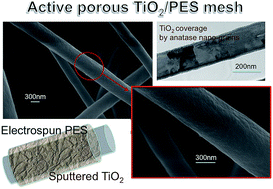
We propose a low temperature approach based on combining an electrospinning methodology and reactive sputtering processes to realise a porous mesh of polyethersulfone (PES) fibers (∼700 nm in diameter) wrapped by TiO2 nano-sheaths, active under UV illumination. The mesh has a porosity as high as ∼91% in volume and was prepared at T ≤ 160 °C. The effectiveness of the TiO2/PES mesh under UV was proved by Methylene Blue (MB) dissociation experiments and related to the TiO2 coverage properties, namely its thickness (∼15 nm), its nano-structuring (grains diameter 8–10 nm) and lattice structure (anatase) that improve the photo-activity action. The combination of electro-spinning plus sputtering processes lays the basis for high porosity and low cost, high throughput, high yield and flexible purifying filter technologies.
1. Introduction
TiO2 is a versatile material used in different fields of applications, spreading from photovoltaics1,2 to gas sensing to photodegradation of pollutant (dye, pesticide, drug) species.3 For photo-activity, TiO2 can in principle be used as free nano-particles. Nevertheless in the applications as filters or purifiers, the nano-particles would need a supporting material to avoid their dispersion in the aqueous solution and their subsequent recovery after detoxification. Thereby, various approaches have been proposed based on TiO2 nanoparticles entrapped in mesoporous meshes or membranes (1D nanostructures). In such systems, the surface area of the active TiO2 and its electronic structure (e.g. in rutile or anatase) are crucial parameters to improve the efficiency of the system.
Anatase nano-particles are usually chemically synthesized by simple and low cost procedures;4 on the other hand, the need of high temperature processes (≥450 °C), used for the solvent release, makes the chemical routes not convenient in several cases. To reduce the thermal budget and, at the same time, to achieve a better control of the structure of the material over large area, physical deposition methods are preferred. By sputtering processes, TiO2 layers with amorphous structures are formed at room temperature, turning in the anatase form by applying post deposition thermal treatment at, or, above 300 °C.5 The presence of a compliant substrate can help achieving the desired anatase lattice structure at temperature even under 300 °C.6 Guaranteeing anatase formation at low temperature still remains a challenge.
The working principle for TiO2 photoactivity is based on its capability in absorbing UV radiation, being the material a direct high band-gap semiconductor, with energy gap (Eg) ∼3.2 eV in the anatase polymorphism.7,8 The photo-generated electrons react with the oxygen molecules and produce superoxide radical anions (O2−), while the photo-generated holes react with the water in the environment by generating (OH˙) radicals. O2− and OH˙ radicals are effective for the decomposition of organic molecules;9 their activity is usually measured by monitoring the methylene blue degradation under UV irradiation, using a standard procedure.10 A wide spread of approaches for the preparation of TiO2-based mesoporous blends was reported in the literature basically with the intent of: (a) increasing the surface to volume ratio of the supporting material so that the photoactivity action is maximised; (b) embedding and anchoring the greatest amount of TiO2 to the support in the anatase form; (c) increasing the mesh porosity for filtering actions. Hereafter, some examples are recalled: (i) TiO2/carbon composite materials were synthesized with a hierarchically porous structure by employing a filter paper as supporting material and by depositing the TiO2 by evaporation-induced self-assembly method with calcination at 350 °C;11 (ii) carbon nanotubes (CNTs) combined with chemically sensitized TiO2, calcinated at 500 °C, were used to promote the separation of the electron–hole charges generated upon irradiation;12 (iii) silicon nanostructures were covered by TiO2 using Atomic Layer Deposition (ALD) methods at a depositions temperature of 200 °C.13,14
To reduce the costs and to increase the mesh flexibility for filtering purposes, hybrid combination of materials is recently preferred compared to totally inorganic blends, as the next generation solutions for photoactivity actions.15 This combination of materials therefore imposes a drastic reduction of the thermal budget over the mesh. In this direction, some attempts were done to use polyethersulfone (PES) membranes, prepared via immersion precipitation, as supporting material for TiO2 nanoparticles. The TiO2-coated membranes were then obtained by dipping the neat in TiO2 suspensions.16 PES is a material that fits fundamental requirements for the realization of filtrating membranes since it combines excellent mechanical properties, hydrolytic stability at pH levels from 2 to 13, and easy and effective sterilisation procedures with different techniques.17,18 Leading companies, for example Solvay, offer a tailored range of products based on PES chemistry for water treatment membranes. PES is a high glass transition (Tg) material, being characterized by Tg in the range of 190–230 °C depending on the chain structures19 and the functional end-groups.20 More recently, it was reported the preparation of a PES membrane filled with TiO2 nanoparticles by hydrolysis of titanium tetraisopropoxide; the as obtained TiO2 nanoparticles were amorphous, and this would require an additional annealing procedure above 400 °C to induce crystallization in anatase.21 However, processing temperatures above 400 °C are not suitable for PES, as demonstrated by several studies on thermal stability of PES.22
For application purposes, simple and low cost approaches must be therefore preferred to complex and expensive nano-structuring procedures, such as photolithography, ALD depositions, silicon-based technologies. An approach implementable in roll to roll fabrication procedures would be also desirable since it enables high volume continuous production for the active membranes. Low temperature processes must be also preferred to assure compatibility with not expensive flexible supports (e.g. T ≤ 200 °C). Flexible and porous supporting materials showing a high active coverage can be also employed as purifying filters in a flowing medium.
For all those reasons we propose a method that combines the electrospun of a network of PES fibers with the sputtering deposition of thin TiO2 anatase layers for flexible purifying systems. The mesh was realised at ≤160 °C. The effectiveness of the TiO2 coverage in the porous PES matrix was demonstrated in comparison to references cases during photo-catalytic activity under UV illumination.
2. Experimental
2.1. PES mesh
The thermoplastic polymer was a polyethersulfone (PES) commercialized as Veradel 3000P by Solvay™, Belgium. Veradel 3000P has a glass transition temperature of 220 °C and a solution viscosity, tested for a solution 25% wt in dimethylacetamide at 40 °C, of 1450 mPa s. Veradel 3000P is commercialized for water treatment membranes. The PES membranes were prepared by dissolving 5 g of Veradel 3000P powder in a solvent mixture (5 ml N,N-dimethylformamide [DMF] and 5 ml of toluene), stirring for 2 h at 40 °C. This solution was placed in a 3 ml medical syringe. The PES membranes were electrospun at room temperature over an Al foil at a flow rate of 60 μL min−1, 21 kV ddp and a 10 cm needle-collector gap onto a rotating drum (200 rpm) covered with antistatic paper. Electrospinning was carried out on a EC-DIG electrospinning apparatus purchased from IME Technologies, Netherlands. The specific surface area of the PES mesh is ∼4 m2 g−1.
2.2. TiO2/PES
Inside the PES mesh, a TiO2 coverage was realised over the fibers by depositing Ti by DC Reactive Sputtering (Kenotec equipment) in O2 ambient starting from a 6′′ titanium target plate having an effective 5′′ erosion zone. The PES fibers are not removed from the aluminium foil before sputtering process. The deposition was carried out by applying a power of ∼600 W for 960 s, at an effective temperature of ∼150 °C. An O2/Ar flow-rate ratio as low as of 5/45 sccm was set in order to maintain a low growth rate (0.06 nm s−1) and to fit the proper layer stoichiometry. The process was set in the oxidized mode at a pressure of 8.5 microbar with an anode–cathode distance of 10 cm. Each deposition process is preceded by a pre-sputtering step to clean up the surface of the Ti target and to remove residual thin oxide layer. The PES mesh covered by Ti–O was annealed in air at 160 °C for 30 minutes (stabilising annealing, slightly above the deposition Ti but for prolonged time), in order to improve the quality of the coverage (ref. 1, 2, 6 and 23). A reference sample was prepared for comparison, by depositing a TiO2 layer over a glass substrate using the same conditions applied on PES.
2.3. Characterizations
2.3.1. SEM, EDX and pore size analyses. SEM micrographs were obtained with a Zeiss EVO equipped with a Bruker EDX Quantax. SEM analysis was carried out on the electrospun veils that were gold sputtered before the analysis without any other pre-treatment. The diameter of the nanofibers was determined from the SEM images with the software Fibraquant. The EDS analysis has been performed using an Oxford x-Act 10 mm2 SSD detector. The sampling volume is about 0.5 mm3 (spot area 1 mm2). Quantitative elemental concentrations have been determined by analysing single spots.
2.3.2. TEM analyses. The mesh was softly scratched over a Cu-grid and analysed by transmission electron microscopy using a JEOL JEM 2010 Microscope operating at 200 kV. With this method, single wires were isolated and their nanostructure investigated in details. Selected Area Diffraction (SAD) and dark field analyses were coupled to the images in order to identify the composition of the coverage.
2.3.3. Pore size and porosity. The pore dimensions for the electrospun PES fibers were measured by a PMI capillary flow porometer (Porous Materials Inc., USA). In the procedure, the sample is immersed in Fluorinert FC-40® (surface tension 16.0 dynes per cm). The bubble point and the pore distribution were calculated with the software Caprep (Porous Materials Inc., USA). The test was repeated two times.The porosity, εm, was determined by gravimetric method. This method is based on the measurement of the void fraction, i.e. is the volume of the pores divided by the total volume of the electrospun PES fibers. Samples weight was measured again after 24 h immersion in kerosene. The overall porosity was calculated according to the following equation:
|
 | (1) |
where
w1 is the weight of the wet electrospun PES fibers;
w2 is the weight of the dry membrane;
Dk is kerosene density (0.82 g cm
−3);
Dp is PES density (1.37 g cm
−3).
Measurements were carried out in triplicate. Results were averaged and the standard deviation was calculated for each sample.
2.3.4. Methylene blue (MB) photodegradation. Volumes of 3 ml of MB aqueous solutions 1.0 μM were put in polystyrene UV-Vis cuvettes and kept in dark for at least 90 min to allow system stabilization. After stabilization, the solutions were irradiated at 366 nm, under constant stirring for 240 min. MB concentration changes before and after irradiation onset were monitored by UV-Vis spectroscopy from the absorbance band at 664 nm (measured range 300–800 nm). The photocatalytic activity supplied by the TiO2/PES meshes was compared with those exhibited by the pure components, namely the PES meshes and a flat TiO2 thin film deposited on glass. In the photo-degradation experiments, we used a 0.5 cm × 0.5 cm area of flat TiO2/glass and a volume of 0.5 cm × 0.5 cm × (8–10) microns of porous meshes (PES and TiO2/PES).
3. Results and discussions
3.1. SEM characterization
The mesh morphology was evaluated by SEM analyses, before and after the Ti deposition in presence of oxygen species (reactive ambient). The mesh has a high degree of porosity due to the long fibers mutually intersecting along the mesh thickness (Fig. 1a). The surface of the fibers is relatively smooth and no beads and droplets within the area inspected by SEM can be observed; the average fiber diameter is around 710 nm ± 360 nm. The membrane showed an average pore diameter of 5.3 μm with maximum diameter of 6.65 μm. The porosity was 91.4% ± 1.1.
 |
| Fig. 1 (a and b) SEM images and diameter distribution of the fibers in the mesh. (c) A detail of a fiber with a corrugated surface, due to the superimposition of a material different from PES. (d) EDX analyses over the fibers, before and after sputtering deposition: Ti species are present over the fibers after deposition. | |
Fig. 1a and b show SEM images of the electrospun fibers after reactive sputtering of the Ti species in presence of oxygen and subsequent stabilising annealing at 160 °C. The overall morphology was apparently (macroscopically) not modified compared to the as deposited PES mesh with the porosity not affected by the deposition process. The final fiber diameter distribution is shown in the inset of Fig. 1b†.
Fig. 1c zooms into the mesh to show single fibers. Differently from what found before sputtering deposition (see ESI†), the surface of the wire has a corrugated habit that gives a preliminary indication of the presence of an extra material over the PES fibers. The nature of the coating was investigated by EDX analyses, statistically performed on the mesh. In Fig. 1d, a typical spectrum of the PES alone (black line) is compared to those of the PES sputtered with Ti–O before (red line) and after (green line) post deposition annealing at 160 °C. The annealing was used to harden the coverage in view of using the mesh in a aqueous bath for the MB photodegradation. The EDX spectra give a clear indication of the presence of Ti species over the PES after sputtering deposition, with the Ti staying on the PES surface even after annealing. Our first attempt to determine the composition of the coverage was done by the X-ray diffraction analyses (see ESI†). The investigation demonstrates the formation of anatase with its typical peak at 2θ = 25.3° (101 crystallographic planes).
3.2. TEM characterization
The local structure of the coverage over the stabilised PES wires was investigated by TEM analyses. Some representative results are shown in Fig. 2 which highlight the morphology of isolated wires (a and b) and of a network of wires in dark field condition (c). In the inner part of the wires, integrated information on the PES plus the coverage is achieved. Fig. 2a indeed shows a PES wire covered by a network of small nano-grains (8–15 nm in diameter), connected one to each other in form of large arrays (100–200 nm each). On the other hand, at the two edges of the wire the nano-grains of the coverage are not superimposed to the PES fiber. From the edge of the fiber, the thickness of the coverage can be thus measured with high precision: it is 15 nm-thick, on both sides of the wire. Thereby, a conformal and continuous coverage enveloping the wire can be deduced from the image. Depending on the side exposed to the Ti–O flux during sputtering deposition, the coverage can lessen from side to side due to shadowing effects (by the wire itself) occurred during deposition, as documented in Fig. 2b. In cases like that, the thickness of the coverage can spread out from ∼40–60 nm to a few nanometers going from one side to the other.
 |
| Fig. 2 TEM analyses of (a and b) single wires in the mesh; (c) dark field analyses and SAD (inset) of an array of wires. Conformal layers of anatase was deposited over the PES wires, being arranged on the PES surface as small nanocrystals. | |
In the statistics of the analysed wires, we found that most of the PES fibers are fully enveloped by a continuous layer made of nano-sized TiO2 domains. The coating follows the shape of the PES fibers with certain variability in the thickness due to shadowing effects. This realises a “core–shell” structure. The conformal coverage is an important achievement arising from the proper calibration of the deposition parameters, with main roles played by the low deposition rate and by the pervasive reactive ambient. We also believe that the electrostatic forces (e.g. due to π electrons presents on the PES aromatic rings, or to charges induced by the sputtering process itself) on the wire surfaces might have had a role in further promoting the conformality of the coverage (compliant substrate).
The chemical composition and the lattice structure of the coverage were finally revealed by diffraction analyses on selected area (SAD) of the blend. In the inset of Fig. 2c, a SAD taken over the fiber network of Fig. 2c shows the typical diffraction spots of the anatase phase. This confirms that a reaction has occurred, with TiO2 as the product in the desired polymorphism,24 as introduced by the XRD results (ESI†). As a further confirmation of the occurred reaction on the wire surface (not as isolated TiO2 aggregates), Fig. 2c shows the dark field image taken by selecting the (101) diffraction spots over the anatase ring at d = 0.351 nm (see square in the SAD). In the dark field images, the brilliant regions are nano-domains of TiO2 arranged in the anatase lattice and exposing the selected (101) lattice planes. Note that the brilliant grains are seated from side to side of the large fiber, thus highlighting the capability of the reactive sputtering process to also cover extended surfaces. The distribution of nanograins over the fiber surface can be completed by moving the SAD over the rest of the diffraction spots shown in the inset. A similar nano-structuring of the TiO2 layer in form of a porous matrix with small grains (8–15 nm) was found in the reference TiO2 layer deposited on glass with the same deposition procedure, and mainly attributed to the deposition conditions used (see ref. 6, 23, 25 and 26). In particular, the nanoporosity was related to a combination of deposition temperature and Ar/O2 ratio, as predicted by the Thornton model.27 Anatase crystallization, not expected under 200 °C, was here mainly related to the low deposition rate used which indeed creates seeds to be more easily crystallised in a porous matrix by a mild thermal treatment rather than in a compact layer.
Although the majority of cases examined by TEM fall into the category described above and illustrated in Fig. 2 with the thin TiO2 layer wrapping the PES fiber from side to side, the occurrence of shadowing effects due to the fiber intersection in dense zones can not be excluded during deposition. It was however verified that Ti penetrated well inside the mesh by EDX analyses performed on both side of the mesh since it can be easily separated from the Al foil and turned from side to side. A final proof of the effective TiO2 coverage is furnished by the photo-degradation results.
3.3. MB degradation
We used the mesh covered by the anatase nano-domains to test its capability in the photodegradation action on a typically used molecule marker, the methylene blue (MB), which is a dye belonging to the tyazine family. Since the quantitative comparison with other results in the literature is made difficult by the required normalization to the exposed surface, we used our TiO2 layer deposited on glass as a reference; the comparison is corroborated by the fact that the anatase layer covering the PES fibers has an identical morphology as the layer on glass.23,26 The reference flat sample has a size of 0.5 cm × 0.5 cm. Fig. 3a compares the photodegradation of MB solution either in the absence of any catalyst or in the presence of catalytic materials such as: PES/TiO2 net, uncovered PES net and flat TiO2 on glass. The comparison between the reference (PES) and the sample (PES covered by TiO2) was done at fixed volume of the mesh (sample area 0.5 cm × 0.5 cm) and at a fixed MB solution concentration. The mesh mass density is ∼1.37 g m−2 and the solution concentration is 1 × 10⁻⁵ mol l−1 (C0).
 |
| Fig. 3 (a) Photodegradation of a MB water solution (1 × 10⁻⁵ M) either alone (open squares) or in the presence of PES (circles), PES/TiO2 (triangles) and TiO2 flat (open triangles). Before UV irradiation (254 nm), MB solution was kept in dark for at least 2 h. After stabilization, no concentration changes were observed until the starting of irradiation. (b) Dependence of the ln(C0/Cx) upon time for different systems. | |
The photodegradation activity of samples was monitored by UV-Vis spectrometric measurements of the variation upon time of the residual MB concentration (Cx) under UV irradiation at 366 nm (Fig. 3). Note that, before the photodegradation measurements, MB solutions were kept in dark for at least 90 min, to allow adsorption phenomena (on the cuvette wall and on the sample themselves) reaching equilibrium condition.8 After stabilization, the MB concentration remains constant (Fig. 3a) until the triggering of photodegradation reactions.
Fig. 3a shows that both PES/TiO2 and flat TiO2 samples possess some catalytic activity since in both cases MB degradation is significant higher than those observed for MB direct photodecomposition and for MB decomposition in the presence of PES alone. A poor activity by PES alone is expected on the basis of the absence of effective photocatalytic species on the surface:28 the activity measured on the membrane is due to radicals species originated by the photooxidation process on the PES surface. The formation of radicals under UV is mainly attributed to the diphenylethersulfone site: in presence of oxygen, in fact, the irradiation causes chain scissions and the cleavage of the aromatic rings. The capability of releasing radical species has been tested by the use of MB, which is known to be oxidized in presence of RO˙ agents.29
We thus noted that (1) the PES/TiO2 activity is well above that of the PES mesh alone thus evidencing the effectiveness of the coverage and the active role of the coverage on the PES mesh; (2) a slightly higher efficiency is found for PES/TiO2 compared to flat TiO2. This last finding is attributed to the comparable active surface area exposed by the two systems to the photo-degradation activity (see Experimental section). The volume of the PES mesh is, in fact, extremely porous with ∼91% of voids. Compared to the flat case, such a high porosity of the mesh offers the perspective of integrating our combined system (flexible PES plus active TiO2 sheet) in filter technologies.
The kinetics of the photodegradation generally obeys a Langmuir–Hinshelwood30–32 mechanism, which can be expressed as follows:
|
 | (2) |
where
K is the adsorption equilibrium constant and
kr is the reaction rate constant. For diluted solutions (
C < 10
−3 M), the reaction becomes of the apparent first order:
|
 | (3) |
where
ka is the rate constant of the apparent first order.
Fig. 3b shows the dependence of ln(C0/Cx) upon time for the various samples. After an initial time in which a fast MB photodegradation was observed in all samples, the system seems to reach a stationary state for which ln(C0/Cx) increases linearly with time. From the linear portion of the plots it was possible to estimate the values of the rate constant for MB alone and for the different samples, as reported in Table 1.
Table 1 Kinetic constant (ka) for first order degradation
|
MB |
PES |
PES/TiO2 |
Flat TiO2 |
ka (min−1) |
1.7 ± 0.1 × 10⁻⁴ |
1.7 ± 0.2 × 10⁻⁴ |
7.2 ± 0.7 × 10⁻⁴ |
4.4 ± 0.6 × 10⁻⁴ |
The data in the table highlights that the TiO2/PES mesh (1) has a kinetic constant about twice the value measured on the reference sample; (2) it exhibits a photocatalytic behaviour which competes with those reported in the literature.8,9,11,13,14,33
4. Conclusions
An active porous mesh of electrospun PES fibers, wrapped by sputtered thin TiO2 layers (∼15 nm), was realized. The mesh exhibits photodegradation properties. With respect to the single components, the blend of materials combines the flexibility and high porosity of PES mesh with the high photo-degradation capability of TiO2. Their intimate core–shell structure was achieved thanks to the high porosity of the PES coupled with the proper sputtering deposition conditions (low deposition rate, reactive plasma etc.). The active role of the mesh is indeed assigned to the thin TiO2 coverage being in the convenient form of nano-crystals with the anatase lattice structure. Anatase crystallization at such low temperature is unexpected and here mainly attributed to the low deposition rate used over a likely compliant substrate. The TiO2 crystallization in the anatase lattice with thin film habit represents the prerequisite to improve the mesh photo-activity and to reduce electron–hole recombination processes.
The photo-degradation behaviour of our TiO2/PES mesh competes with those reported in the literature, as taking into account (1) the low thermal budget applied to fabricate the blend (≤160 °C), (2) the capability of enveloping the PES fibers with an anatase layer, (3) the large porosity of the mesh.
The combination of electro-spinning plus sputtering processes poses the basis for high porosity and low cost, high throughput, high yield and purifying flexible filter technologies.
Acknowledgements
This work was developed in the framework of the Italian Project “Elettronica su Plastica per Sistemi Smart disposable” (Electronics on Plastics for ‘Smart disposable’ Systems) funded by MIUR (Ministero Istruzione Università e Ricerca) to the Distretto Tecnologico Sicilia Micro e Nano Sistemi by means of the Italian Program PON02_00355_3416798.
References
- A. Alberti, G. Pellegrino, G. G. Condorelli, C. Bongiorno, S. Morita, A. L. Magna and T. Miyasaka, Efficiency Enhancement in ZnO: Al-Based Dye-Sensitized Solar Cells Structured with Sputtered TiO2 Blocking Layers, J. Phys. Chem. C, 2014, 118, 6576 CAS.
- A. Alberti, L. D. Marco, G. Pellegrino, G. G. Condorelli, R. Giannuzzi, R. Scarfiello, M. Manca, C. Spinella, G. Gigli and A. La Magna, Combined Strategy to Realize Efficient Photoelectrodes for Low Temperature Fabrication of Dye Solar Cells, ACS Appl. Mater. Interfaces, 2014, 6, 6425 CAS.
- B. Weng, S. Liu, Z.-R. Tang and Yi-J. Xu, One-dimensional nanostructure based materials for versatile photocatalytic applications, RSC Adv., 2014, 4, 12685 RSC.
- K. Yanagisawa and J. Ovenstone, Crystallization of Anatase from Amorphous Titania Using the Hydrothermal Technique:
Effects of Starting Material and Temperature, J. Phys. Chem. B, 1999, 103, 7781 CrossRef CAS. - R. Gago, A. Redondo-Cubero, M. Vinnichenko and L. Vazquez, Annealing of heterogeneous phase TiO2 films: an X-ray absorption and morphological study, Chem. Phys. Lett., 2011, 511, 367 CrossRef CAS PubMed.
- G. Pellegrino, C. Bongiorno, S. Ravesi and A. Alberti, Fiber texturing in nano-crystalline TiO2 thin films deposited at 150 °C by DC-reactive sputtering on fiber-textured [0
0
0
1] ZnO
:
Al substrates, J. Phys. D: Appl. Phys., 2012, 45, 355301 CrossRef. - M. M. Gomez, N. Beermann, J. Lu, E. Olsson, A. Hagfeldt, G. A. Niklasson and C. G. Granqvist, Sol. Energy Mater. Sol. Cells, 2003, 76, 37–56 CrossRef CAS.
- M. M. Gomez, J. Lu, E. Olsson, A. Hagfeldt and C. G. Granqvist, Sol. Energy Mater. Sol. Cells, 2000, 64, 385–392 CrossRef CAS.
- H. Chang, C. Su, C.-H. Lo, L.-C. Chen, T.-T. Tsung and C.-S. Jwo, Photodecomposition and Surface Adsorption of Methylene Blue on TiO2 Nanofluid Prepared by ASNSS, Mater. Trans., 2004, 45, 3334–3337 CrossRef CAS.
- A. Mills, C. Hill and P. K. J. Robertson, Overview of the current ISO tests for photocatalytic materials, J. Photochem. Photobiol., A, 2012, 237, 7–23 CrossRef CAS PubMed.
- L. Hu, H. Wei, Y. Zhang, S. Zhang and B. Li, TiO2/carbon paper composite materials with hierarchically porous structure for photocatalysis, Mater. Lett., 2014, 119, 88–91 CrossRef CAS PubMed.
- Z. Li, B. Gao, G. Z. Chen, R. Mokaya, S. Sotiropoulos and G. L. Puma, Carbon nanotube/titanium dioxide (CNT/TiO2) core–shell nanocomposites with tailored shell thickness, CNT content and photocatalytic/photoelectrocatalytic properties, Appl. Catal., B, 2011, 110, 50–57 CrossRef CAS PubMed.
- V. Scuderi, G. Impellizzeri, L. Romano, M. Scuderi, G. Nicotra, K. Bergum, A. Irrera, B. G. Svensson and V. Privitera, TiO2-coated nanostructures for dye photo-degradation in water, Nanoscale Res. Lett., 2014, 9, 458 CrossRef PubMed.
- V. Scuderi, G. Impellizzeri, L. Romano, M. Scuderi, M. V. Brundo, K. Bergum, M. Zimbone, R. Sanz, M. A. Buccheri, F. Simone, G. Nicotra, B. G. Svensson, M. G. Grimaldi and V. Privitera, An enhanced photocatalytic response of nanometric TiO2 wrapping of Au nanoparticles for eco-friendly water applications, Nanoscale, 2014, 6, 11189 RSC.
- K. R. Reddy, M. Hassan and G. V. Gomes, Nanostructures based on titanium dioxide for enhanced photocatalysis, Appl. Catal., A, 2015, 489, 1–16 CrossRef CAS PubMed.
- A. Rahimpour, S. S. Madaeni, A. H. Taheri and Y. Mansourpanah, Coupling TiO2 nanoparticles with UV irradiation for modification of polyethersulfone ultrafiltration membranes, J. Membr. Sci., 2008, 313, 158–169 CrossRef CAS PubMed.
- Z.-M. Huang, Y.-Z. Zhang, M. Kotaki and S. Ramakrishna, A review on polymer nanofibers by electrospinning and their applications in nanocomposites, Compos. Sci. Technol., 2003, 63, 2223–2253 CrossRef CAS.
- S. Homaeigohar and M. Elbahri, Nanocomposite Electrospun Nanofiber Membranes for Environmental Remediation, Materials, 2014, 7, 1017–1045, DOI:10.3390/ma7021017.
- L. Abate, I. Blanco, G. Cicala, A. Mamo, G. Recca and A. Scamporrino, The influence of chain rigidity on the thermal properties of some novel random copolyethersulfones, Polym. Degrad. Stab., 2010, 95, 798–802 CrossRef CAS PubMed.
- L. Abate, L. I. Blanco, G. Cicala, G. Recca and A. Scamporrino, The influence of chain ends on the thermal and rheological properties of some 40/60 PES/PEES copolymers, Polym. Eng. Sci., 2010, 49, 1477–1483 Search PubMed.
- K. Fischer, M. Grimm, J. Meyers, C. Dietrich, R. Gläser and A. Schulze, Photoactive microfiltration membranes via directed synthesis of TiO2 nanoparticles on the polymer surface for removal of drugs from water, J. Membr. Sci., 2015, 478, 49–57 CrossRef CAS PubMed.
- F. Samperi, C. Puglisi, R. Messina, T. Ferreri, G. Cicala, A. Recca, C. L. Restuccia and A. Scamporrino, Thermal decomposition products of copoly(arylene ether sulfone)s characterized by direct pyrolysis mass spectrometry, Polym. Degrad. Stab., 2007, 92, 1304–1315 CrossRef CAS PubMed.
- A. Alberti, C. Bongiorno and G.- Pellegrino, Anatase/rutile nucleation and growth on (0002) and (11-20) oriented ZnO: Al/glass substrates at 150°C, Thin Solid Films, 2014, 555, 3 CrossRef CAS PubMed.
- T. Luttrell, S. Halpegamage, J. Tao, A. Kramer, E. Sutter and M. Batzill, Why is anatase a better photocatalyst than rutile? – Model studies on epitaxial TiO2 films, Sci. Rep., 2014, 4, 4043 Search PubMed.
- G. Pellegrino, G. G. Condorelli, V. Privitera, B. Cafra, S. Di Marco and A. Alberti, Dye-sensitizing of self-nanostructured Ti(:Zn)O2/AZO transparent electrodes by self-assembly of 5,10,15,20-tetrakis(4-carboxyphenyl)porphyrin (TCPP), J. Phys. Chem. C, 2011, 115, 7760 CAS.
- G. Pellegrino, A. Alberti, G. G. Condorelli, F. Giannazzo, A. La Magna, A. M. Paoletti, G. Pennesi, G. Rossi and G. Zanotti, Study of the Anchoring Process of Tethered Unsymmetrical Zn-Phthalocyanines on TiO2 Nanostructured Thin Films, J. Phys. Chem. C, 2013, 117, 11176–11185 CAS.
- J. A. Thornton, The microstructure of sputter-deposited coatings, J. Vac. Sci. Technol., A, 1986, 4, 3059 CAS.
- A. Rivaton and J. L. Gardette, Photodegradation of polyethersulfone and polysulfone, Polym. Degrad. Stab., 1999, 66, 385–403 CrossRef CAS.
- A. Houas, H. Lachhe, M. Ksibi, E. Elaloui, C. Guillard and J.-M. Herrmann, Photocatalytic Degradation Pathway of Methylene Blue in Water, Appl. Catal., B, 2001, 31, 145–157 CrossRef CAS.
- D. F. Ollis, N. Serpone and E. Pelizzetti, in Photocatalysis Fundamentals and Applications, ed. N. Serpone and E. Pelizzetti, Wiley, New York, 1989, pp. 603–638 Search PubMed.
- M. A. Fox and M. T. Dulay, Heterogeneous Photocatalysis, Chem. Rev., 1993, 93, 341–357 CrossRef CAS.
- S.-S. Lin and M. D. Gurol, Catalytic Decomposition of Hydrogen Peroxide on Iron Oxide: Kinetics, Mechanism, and Implications, Environ. Sci. Technol., 1998, 32, 1417–1423 CrossRef CAS.
- J. Lin, X. Liu, S. Zhu, Y. Liu and X. Chen, Anatase TiO2 nanotube powder film with high crystallinity for enhanced photocatalytic performance, Nanoscale Res. Lett., 2015, 10, 110 CrossRef PubMed.
Footnote |
† Electronic supplementary information (ESI) available. See DOI: 10.1039/c5ra13153g |
|
This journal is © The Royal Society of Chemistry 2015 |
Click here to see how this site uses Cookies. View our privacy policy here.