
Palladium nanoparticle functionalized graphene nanosheets for Li–O2 batteries: enhanced performance by tailoring the morphology of the discharge product†
Liang Jun Wangab,
Jian Zhangc,
Xiao Zhaoc,
Lei Lei Xuc,
Zhi Yang Lyuc,
Min Laia and
Wei Chen*bcde
aSchool of Physics and Optoelectronic Engineering, Nanjing University of Information Science & Technology, Nanjing 210044, Jiangsu, China
bDepartment of Physics, National University of Singapore, 2 Science Drive 3, 117542, Singapore. E-mail: phycw@nus.edu.sg; Fax: +65 6777 6126; Tel: +65 6516 2921
cDepartment of Chemistry, National University of Singapore, 3 Science Drive 3, 117543, Singapore
dCentre for Advanced 2D Materials and Graphene Research Centre, National University of Singapore, 6 Science Drive 2, 117546, Singapore
eNational University of Singapore (Suzhou) Research Institute, Suzhou 215123, China
First published on 24th August 2015
Abstract
Tailoring the morphology of the cathode discharge product is essential for developing high-capacity and rechargeable lithium oxygen (Li–O2) batteries. In this work, by using functionalized graphene nanosheets (GNSs) with uniformly dispersed palladium nanoparticles (Pd NPs) as the cathode catalyst for the Li–O2 battery, the discharge product of the nano-sized Li2O2 particles formed and homogeneously deposited on GNSs. Through this tailored morphology, the Li–O2 batteries with the Pd functionalized GNS catalyst possessed an increased capacity up to 7690 mA h g−1 at a current density of 0.08 mA cm−2. Meanwhile, reduced charge/discharge overpotentials and good cyclability were obtained.
1. Introduction
The growing demands for green energy require the rapid development of energy storage devices with high capacity. Among all the rechargeable batteries, lithium oxygen batteries, which possess high theoretical energy density (11![[thin space (1/6-em)]](https://www.rsc.org/images/entities/char_2009.gif) 431 W h kg−1 excluding oxygen weight),1 represent a promising candidate for the next generation electric vehicles.2,3 Despite the attractive prospect, some issues including large overpotentials, poor recyclability and unstable electrolyte4–9 limit the wide applications of Li–O2 batteries.
431 W h kg−1 excluding oxygen weight),1 represent a promising candidate for the next generation electric vehicles.2,3 Despite the attractive prospect, some issues including large overpotentials, poor recyclability and unstable electrolyte4–9 limit the wide applications of Li–O2 batteries.
Cathode catalysts play a significant role to improve the overpotentials and cyclability.10–12 It is of desperate needs to develop a high-efficiency cathode catalyst for Li–O2 batteries. Following the transition metal oxides catalysts introduced by Bruce and co-workers,13,14 numerous efforts have been devoted to improving the discharge capacity by employing various catalysts in oxygen electrode. Shao-Horn et al. first reported noble metals catalysts for a Li–O2 battery. It was found that Au and Pt can promote the oxygen reduction reaction (ORR) and oxygen evolution reaction (OER) process, respectively.15 In addition, perovskite based oxides such as LaNiO3 nanocubes16 and three-dimensional ordered macroporous LaFeO3 (ref. 17) were also found to improve the overpotential and discharge capacity of Li–O2 batteries. However, the insoluble and non-conductive nature of discharge product (Li2O2) makes Li–O2 batteries more complex than conventional fuel cells. The deposited solid discharge product may partially block the catalyst surface, making the subsequent charging process with high overpotentials. In other words, the performance of OER process is not only determined by the catalyst itself but also close linked to morphology and electronic conductivity of Li2O2 formed during ORR process.18 A favourable morphology of discharge product will benefit the electrochemical performance of the battery.19 Zhang et al. synthesized free-standing palladium-modified hollow spherical carbon on carbon paper. It was found that this unique structure could facilitate the formation of nanosheet-shaped discharge product which was beneficial to high-rate and long-life Li–O2 batteries.20 Zhuang et al. reported a mud shape morphology in PtRu based catalyst which promoted the oxidation of Li2O2.18 Chen et al. also demonstrated the decrease in Li2O2 size could help to lower the charge plateaus in OER process.21
Herein, we report a strategy to improve the battery performance by tailoring the morphology of discharge product. By using GNSs functionalized with high density and uniformly dispersed Pd NPs as cathode catalyst, the growth and morphology of the discharge products of Li2O2 can be effectively tailored, thereby leading to the improved Li–O2 battery performance. As illustrated in Scheme 1, graphene oxide (GO) was first functionalized with poly(diallyldimethylammonium chloride) (PDDA). The negatively charged palladium precursor was then anchored onto the monodispersed and positively charged PDDA sites of the functionalized GO through electrostatic interaction. The subsequent in situ ethylene glycol reduction results in the formation of homogeneously distributed Pd NPs on GNSs with high density. These small Pd NPs act as nucleation sites for discharge product, leading to the uniform deposition of the Li2O2 nanoparticles on GNSs. The as-prepared catalyst demonstrates improved catalytic activity both for ORR and OER performances. A high discharge capacity of 7690 mA h g−1 can be obtained by the tailored morphology at a current density of 0.08 mA cm−2 and the battery can be cycled over 96 cycles without any capacity degradation at a 500 mA h g−1 capacity limit.
 | ||
| Scheme 1 Schematic illustration of Pd functionalized GNSs cathode catalyst for Li–O2 battery, including Pd NPs are homogeneously grown on GNSs; and the monodispersed Pd NPs with high density can provide sufficient active sites for the nucleation and growth of discharge product, leading to the homogeneous deposition of nano-sized Li2O2 on GNSs. | ||
2. Experimental
GO was purchased from graphene supermarket. PDDA and PdCl2 were provided by Aldrich. Other agents including NH4OH, hydrochloric acid, ethylene glycol and NaCl were of analytical reagent grade and used as received.2.1. Synthesis of PDDA functionalized GO
The procedure to prepare PDDA functionalized GO (GO–PDDA) is as follows:22 typically, GO (60 mg) was dispersed in 150 mL NaCl solution (1 M) and sonicated for 1 h. 240 mg PDDA was subsequently added and sonication was carried out for another 2 h. The resulting functionalized graphene solution was centrifuged and washed with distilled water many times to remove redundant impurities. The final product was dried in a vacuum oven at 30 °C for 50 h.2.2. Synthesis of Pd functionalized GNSs
The obtained GO–PDDA powder was dispersed in 80 mL ethylene glycol solution followed by sonication for 1 h. In order to make the Pd loading ratio to be 20 wt%, 2.8 mL of 0.05 M H2PdCl4 (∼15 mg Pd) solution was added drop wise and 2 h sonication treatment was carried out to make the mixture fully dispersed. Then the pH of the solution was adjusted to 11 by adding concentrated ammonia water solution. The resulting solution was refluxed at 120 °C for 4 h to reduce GO and H2PdCl4. The final reaction product was washed with ethanol and distilled water and freeze-dried to isolate the solid product.2.3. Lithium oxygen battery assembly and testing
The cathode was fabricated by intimately mixing 90 wt% Pd GNSs or GNSs with 10 wt% polyvinylidene fluoride (PVDF) binder in N-methyl-2-pyrrolidone (NMP). The obtained slurry was then coated onto Toray Carbon Paper (TGP-H-060). A typical mass loading of the oxygen cathode is 0.7–0.8 mg cm−2 and the discharge capacity is based on the total mass of the cathode. The cathode was dried at 100 °C for 24 h and transferred to glove box subsequently. The Li–O2 batteries were assembled based on a coin-cell structure, which comprised a lithium foil, glass fiber separator, the fabricated oxygen cathode and 1 M lithium trifluoromethanesulfonate/tetraethylene glycol dimethyl ether (LiCF3SO3/TEGDME) electrolyte. The obtained coin-cells were transported to a home-made pressure-tight glass container which was filled with oxygen.2.4. Characterization
X-ray diffraction (XRD) data was collected on a PANalytical Empyren DY708 diffractometer with Cu radiation. The specific surface area was measured by nitrogen sorption at 77 K on a surface area analyser based on Brunauer–Emmett–Teller (BET) method. Thermogravimetric analysis (TGA) was performed by using TA instrument 2960 under air gas flow at 10 °C min−1 with the temperature range of 30–900 °C. X-ray photoelectron spectroscopy (XPS), transmission electron microscopy (TEM, JEOL 2010) and field emission scanning electron microscopy (FESEM, JEOL JSM6700F) were used to analyse the catalyst and cathodes after discharge and charge. All electrodes after discharge and charge were washed with CH3CN and dried in glove box before further characterization.3. Results and discussion
As shown by the TEM image in Fig. 1a, Pd NPs are homogeneously dispersed on GNSs with size ranging from 2 nm to 5 nm and an average size of 3.56 nm (Fig. 1b). The high dispersion of Pd NPs results from the PDDA functionalized on GNSs, which can act as both a stabilizer and nucleation site for PdCl42−.22 The high resolution transmission electron microscopy (HRTEM) (Fig. 1a, inset) reveals that the interlayer spacing of the NPs is about 0.225 nm, which is in good agreement with the Pd (111) plane. This can be further confirmed by XRD measurement as shown in Fig. S1a,† where the diffraction peaks at 2θ = 39.2°, 45.4°, 66.2° originate from the crystallized metallic palladium (PDF no. 46-1043). The existence of palladium, carbon, oxygen, nitrogen elements was verified by energy dispersive spectroscopy (EDS) (Fig. S1b†) and XPS wide-scan spectrum in Fig. S3a,† with the nitrogen coming from PDDA. The Pd loading ratio was estimated to be 19% from XPS measurement. The result was further supported by the TGA curve in Fig. S2.† The Pd 3d spectrum in Fig. S3b† revealed the existence of two chemical states of Pd, with the lower binding energy component originated from metallic Pd and the higher binding energy component assigned to PdO due to the surface partial oxidation of Pd NPs.23,24 As revealed by XRD and XPS measurements (details can be found in ESI†), GO was partially reduced during the Pd NPs functionalization process. The specific surface area of Pd functionalized GNSs was estimated to be 90.0 m2 g−1 from the N2 adsorption–desorption isotherms in Fig. S4b.† | ||
| Fig. 1 (a) TEM image of the Pd functionalized GNSs, and the inset in panel (a) is the corresponding HRTEM of a single Pd particle. (b) Particle size distribution of the Pd NPs. | ||
The cathodes were prepared by mixing 90 wt% Pd functionalized GNSs or GNSs with 10 wt% PVDF binder in NMP. FESEM was employed to evaluate the morphology of cathodes at the pristine, discharge and charge states, as shown in Fig. 2. After full discharge at the same current density (0.08 mA cm−2), the surface morphologies of the discharge products on both cathodes dramatically differed from each other, as shown in Fig. 2b, c, f and g. For the bare GNSs cathode, the discharge product was irregularly distributed on the surface and some of them showed widely observed toroidal morphology (Fig. 2c).25,26 Such large aggregates can seriously block the charge and ion transfer as well as the oxygen diffusion in the cathode. It has been reported that these large toroidal shaped aggregates cannot be easily decomposed in the subsequent charge process.27 In contrast, on the Pd functionalized GNSs cathode, the densely packed discharge product was homogenously distributed on the cathode in the form of small nanoparticles with an average diameter of ∼25 nm, as shown in Fig. 2f and g. After the full discharge as shown in Fig. 2h, small nanoparticles can be easily decomposed and the Pd functionalized GNSs cathode can recover its original morphology after charge process.
 | ||
| Fig. 2 FESEM image of GNSs (a–d) and Pd functionalized GNSs (e–h) cathodes at different states: pristine (a and e), after discharge (b, c, f and g) and after charge (d and h). | ||
The effects of the tailored morphology of the discharge product on the battery performance were evaluated with a voltage window of 2.0–4.5 V (vs. Li/Li+). The first full discharge–charge profiles of Li–O2 batteries with Pd functionalized GNSs and bare GNSs cathodes at 0.08 mA cm−2 are shown in Fig. 3a. The Li–O2 battery with Pd functionalized GNSs exhibited a discharge plateau of 2.76 V, which was about 35 mV higher than that of the GNSs cathode. Moreover, a discharge capacity as high as 7690 mA h g−1 can be achieved. The obtained capacity was much higher than that of the GNSs cathode (4592 mA h g−1). The high capacity and enhanced ORR activity were proposed to originate from the Pd NPs functionalization. It was reported that Pd exhibited the highest ORR catalytic activity among Pd, Pt, Ru, Au, and glassy carbon.28 The functionalized Pd NPs can improve the discharge potential and effectively facilitate the deposition of the discharge products of Li2O2 on the cathode. At the same time, the highly dispersed Pd NPs with high density can provide sufficient active sites for the nucleation and growth of discharge product.29 This can significantly improve the effective surface area for the discharge product to deposit, thereby enhancing the capacity. It can also prevent the overgrowth of the Li2O2 into large crystals like the large sized aggregates, which are difficult to be completely decomposed during the charge process.17,27 In addition to the enhanced ORR performance, Pd functionalized GNSs also displayed better OER catalytic activity. The charge voltage with Pd functionalized GNSs cathode was lower than that of GNSs cathode by 150 mV. The discharge–charge profiles of the Pd functionalized GNSs and the bare GNSs based batteries under different current densities (0.08, 0.16 mA cm−2) were further examined, as shown in Fig. 3b and c. It is noticed that the battery degradation become obvious with the increase in current density in both cathodes, but Pd functionalized GNSs always showed higher discharge capacity at various current densities. As can be seen in Fig. 3d, the first discharge capacities of Pd functionalized GNSs at 0.08, and 0.16 mA cm−2 reach 7690 and 4912 mA h g−1, respectively, which are higher than 4592 and 3672 mA h g−1 for bare GNSs electrodes. The full discharge–charge cycling performance of the two cathodes at a current density of 0.16 mA cm−2 was further investigated. As shown in Fig. S5,† Pd functionalized GNSs electrode shows better capacity retention than GNSs electrode after three cycles. For Pd functionalized GNSs electrode, over 60% of discharge capacity remained after three cycles, while for GNSs cathode, only 30% of the capacity retained. It is noticed that there are two plateaus in the 1st charge curve for Pd functionalize GNSs, while only one plateau is detected for GNSs cathode. The charge voltage differences may be due to the different Li2O2 deposition mechanisms. Previous reports have demonstrated the existence of the LiO2-like species and metastable LiO2-like species can be decomposed at a low overpotential of 3.5 to 3.8 V.26,30,31 So the first plateau at 3.6 V is proposed to correspond to decomposition of LiO2-like component, while the second plateau at 4.0 V correlates with the oxidation of Li2O2. However, this phenomenon was not observed for the bare GNSs catalyzed battery. This indicates that Pd can promote the formation of LiO2-like species. Our results have shown that Pd functionalized GNSs possessed enhanced catalytic activity to both ORR and OER process.
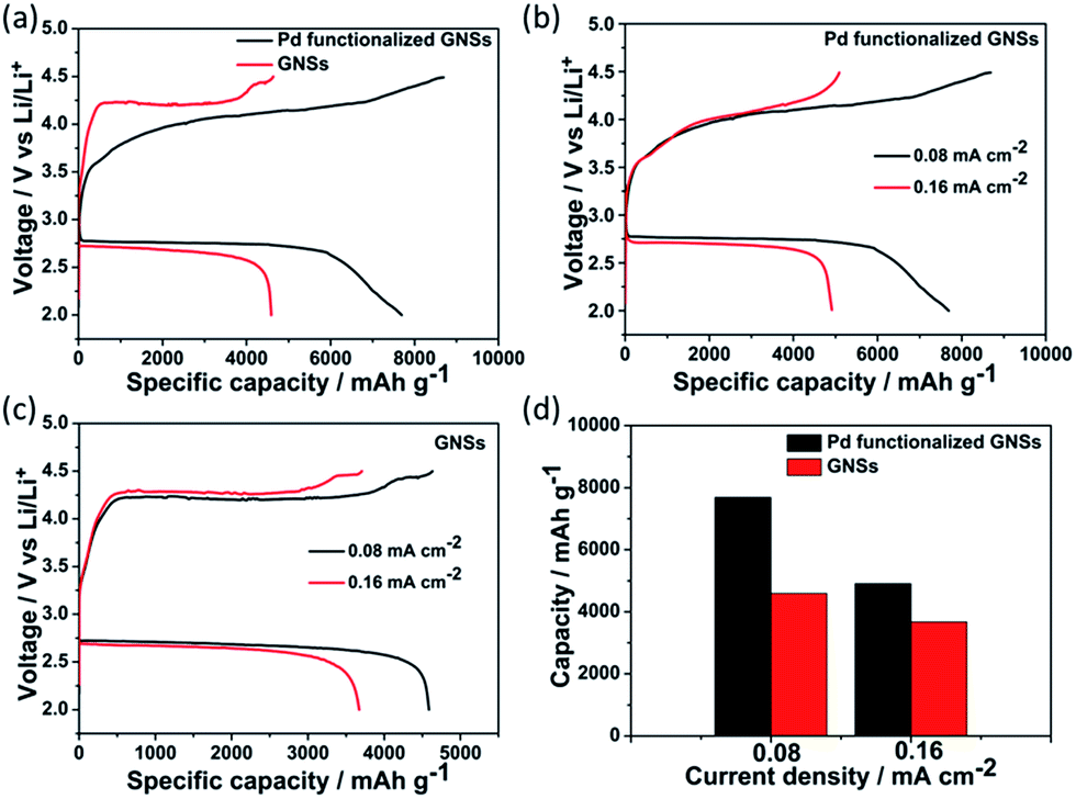 | ||
| Fig. 3 (a) First full discharge–charge profiles of Li–O2 batteries with Pd functionalized GNSs and bare GNSs cathode at a current density of 0.08 mA cm−2. Discharge–charge profiles of (b) Pd functionalized GNSs and (c) bare GNSs at different current densities. (d) Discharge capacities of the two cathodes at different current densities. | ||
The solid discharge product (Li2O2) in Li–O2 batteries coat on the cathode, thus resulting in the passivation of the active sites as well as the gradual battery death due to the insulating nature of the discharge product.32 Controlling the active or the deposition sites on the cathode and the morphology of discharge product is essential for improving both the ORR and OER performance.18,20 For the bare GNSs cathode, because of the lack of sufficient active sites, the discharge products prefer to grow at the surface functional groups and defects sites of GNSs,33–35 thus forming the irregularly large sized aggregates. The large aggregates tend to block the pores on the cathode, moreover, it will hinder the formation of effective Li2O2–electrolyte interfaces and the efficient ion/electron diffusion, thereby resulting in the high overpotential during the subsequent charge process.20,34,36 In contrast, the introduction of Pd NPs on GNSs can provide enough nucleation sites for Li2O2, thus leading to the uniform deposition and distribution of Li2O2 nanoparticles on the cathode. This provides sufficient Li2O2–electrolyte interface and enhances the surface-related transport phenomena, which is beneficial for the three/two-phase electrochemical reaction.21,37 Moreover, the small particle size of the Li2O2 nanoparticles can significantly facilitate the effective decomposition of discharge product and reduce the polarization of electrode, which will help to lower the charging potential in the OER process.21,37 With continuous deposition of Li2O2 on catalyst surface, the catalytic effect may be weakened due to the shielding effect of Li2O2.19 In our case, we cannot exclude the catalytic effect of Pd on Li2O2 oxidation, but the well-tailored morphology is reasonably expected to facilitate the charge process. In summary, the well-tailored morphology of the discharge product can benefit both ORR and OER process.
XPS and XRD were used to characterize the discharge and charge products. As shown by the Li 1s XPS spectra in Fig. 4a, two peaks at the binding energy of 54.5 eV and 55.3 eV were observed and assigned to Li2O2 and Li2CO3, respectively.34,38 The very weak intensity of the Li2CO3 peak indicated that the main discharge product coated on the Pd functionalized GNSs cathode was Li2O2 and the undesirable Li2CO3 was proposed to originate from the decomposition of the electrolyte.5,39 After the full charge, the Li 1s spectrum almost restored to that of the pristine cathode, indicating completely decomposition of the Li-related discharge products. XRD patterns of the pristine, discharge and charge cathode are shown in Fig. 4b. After full discharge, all peaks can be assigned to Li2O2. This indicates that Li2O2 was the main crystalline product during the discharge process. After recharge, all peaks related to Li2O2 completely disappeared and the cathode returned to its original state, consistent with discharge–charge profiles and FESEM results above. The absence of Li2CO3 peak in XRD spectra can be ascribed to its small amount or poor crystallinity, which is in accord with many other reports.34,40,41 These results suggested the reversible nature of Pd functionalized GNSs cathode for Li–O2 batteries.
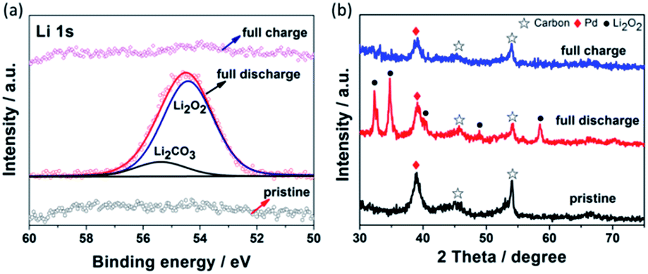 | ||
| Fig. 4 (a) Li 1s XPS spectra, (b) XRD patterns of Pd functionalized GNSs cathode at pristine, full discharge and full charge states. | ||
The cycle stability is an important factor in practical rechargeable Li–O2 batteries. Here, the widely used capacity limited method was used to evaluate the cyclability.42,43 Fig. 5 shows the cycling performance of Pd functionalized GNSs at a current density of 0.08 mA cm−2 and a limited capacity of 500 mA h g−1. It can be seen that there is no capacity decay up to 96 cycles, indicating the good reversibility of the Pd functionalized GNSs cathode. The significant charge–discharge overpotentials increase in the last few cycles may result from electrolyte decomposition and carbon corrosion. It has been reported that cycling process is accompanied by electrolyte decomposition and the corrosion of carbon materials, resulting in the formation of Li2CO3, HCO2Li and CH3CO2Li related side products.5,39 The continuous accumulation of Li2CO3 related side products upon cycling could passivate the cathode material and make the subsequent cycling more and more difficult, and thereby fast capacity fading and battery death. For the bare GNSs cathode in Fig. S6,† the charge overpotentials increase rapidly from the beginning. The high charge overpotentials may induce more side reactions5 and the battery can be only operated for 39 cycles. The improved cycling performance further suggested the advantage of Pd functionalization on GNSs.
 | ||
| Fig. 5 Cycling performance of Li–O2 batteries based on the Pd functionalized GNSs cathode catalyst. | ||
4. Conclusions
In summary, Pd functionalized GNSs was prepared by ethylene glycol reduction method. Compared with the bare GNSs cathode, Pd functionalized GNSs showed enhanced discharge capacity up to 7690 mA h g−1 and improved discharge–charge potentials. Moreover, Pd functionalized GNSs cathode can be operated at 500 mA h g−1 for 96 cycles without any capacity decay. The monodispersed Pd NPs on GNSs can act as ideal nucleation sites for discharge product of Li2O2, leading to the homogeneous coating of densely packed and nano-sized Li2O2 NPs on the cathode. Such tailored morphology of discharge product is beneficial for both the ORR and subsequent OER processes. Our work provides a promising strategy to tailor the morphology and growth of discharge product in Li–O2 batteries with improved battery performance.Acknowledgements
The authors acknowledge the financial support from Singapore MOE grant R143-000-593-112.References
- J. Wang, Y. Li and X. Sun, Nano Energy, 2013, 2, 443–467 CrossRef CAS PubMed.
- M. Park, H. Sun, H. Lee, J. Lee and J. Cho, Adv. Energy Mater., 2012, 2, 780–800 CrossRef CAS PubMed.
- J. Christensen, P. Albertus, R. S. Sanchez-Carrera, T. Lohmann, B. Kozinsky, R. Liedtke, J. Ahmed and A. Kojic, J. Electrochem. Soc., 2012, 159, R1 CrossRef CAS PubMed.
- F. Li, T. Zhang and H. Zhou, Energy Environ. Sci., 2013, 6, 1125 CAS.
- M. M. Ottakam Thotiyl, S. A. Freunberger, Z. Peng and P. G. Bruce, J. Am. Chem. Soc., 2013, 135, 494–500 CrossRef CAS PubMed.
- B. M. Gallant, R. R. Mitchell, D. G. Kwabi, J. Zhou, L. Zuin, C. V. Thompson and Y. Shao-Horn, J. Phys. Chem. C, 2012, 116, 20800–20805 CAS.
- J. Lu, L. Li, J. B. Park, Y. K. Sun, F. Wu and K. Amine, Chem. Rev., 2014, 114, 5611–5640 CrossRef CAS PubMed.
- M. D. Bhatt, H. Geaney, M. Nolan and C. O'Dwyer, Phys. Chem. Chem. Phys., 2014, 16, 12093–12130 RSC.
- R. Black, B. Adams and L. F. Nazar, Adv. Energy Mater., 2012, 2, 801–815 CrossRef CAS PubMed.
- Y. Shao, S. Park, J. Xiao, J.-G. Zhang, Y. Wang and J. Liu, ACS Catal., 2012, 2, 844–857 CrossRef CAS.
- Z. Q. Peng, S. A. Freunberger, Y. H. Chen and P. G. Bruce, Science, 2012, 337, 563–566 CrossRef CAS PubMed.
- Y.-C. Lu, B. M. Gallant, D. G. Kwabi, J. R. Harding, R. R. Mitchell, M. S. Whittingham and Y. Shao-Horn, Energy Environ. Sci., 2013, 6, 750–768 CAS.
- A. Débart, J. Bao, G. Armstrong and P. G. Bruce, J. Power Sources, 2007, 174, 1177–1182 CrossRef PubMed.
- A. Débart, A. J. Paterson, J. Bao and P. G. Bruce, Angew. Chem., Int. Ed., 2008, 120, 4597–4600 CrossRef PubMed.
- Y. C. Lu, Z. C. Xu, H. A. Gasteiger, S. Chen, K. Hamad-Schifferli and Y. Shao-Horn, J. Am. Chem. Soc., 2010, 132, 12170–12171 CrossRef CAS PubMed.
- J. Zhang, Y. Zhao, X. Zhao, Z. Liu and W. Chen, Sci. Rep., 2014, 4, 6005 CAS.
- J.-J. Xu, Z.-L. Wang, D. Xu, F.-Z. Meng and X.-B. Zhang, Energy Environ. Sci., 2014, 7, 2213–2219 CAS.
- Y. Yang, W. Liu, Y. Wang, X. Wang, L. Xiao, J. Lu and L. Zhuang, Phys. Chem. Chem. Phys., 2014, 16, 20618–20623 RSC.
- J. Cao, S. Liu, J. Xie, S. Zhang, G. Cao and X. Zhao, ACS Catal., 2015, 5, 241–245 CrossRef CAS.
- J. J. Xu, Z. L. Wang, D. Xu, L. L. Zhang and X. B. Zhang, Nat. Commun., 2013, 4, 2438–2447 Search PubMed.
- Y. Hu, X. Han, F. Cheng, Q. Zhao, Z. Hu and J. Chen, Nanoscale, 2014, 6, 177–180 RSC.
- J.-D. Qiu, G.-C. Wang, R.-P. Liang, X.-H. Xia and H.-W. Yu, J. Phys. Chem. C, 2011, 115, 15639–15645 CAS.
- X. Zhao, J. Zhu, L. Liang, C. Liu, J. Liao and W. Xing, J. Power Sources, 2012, 210, 392–396 CrossRef CAS PubMed.
- B. van Devener, S. L. Anderson, T. Shimizu, H. Wang, J. Nabity, J. Engel, J. Yu, D. Wickham and S. Williams, J. Phys. Chem. C, 2009, 113, 20632–20639 CAS.
- B. M. Gallant, D. G. Kwabi, R. R. Mitchell, J. Zhou, C. V. Thompson and Y. Shao-Horn, Energy Environ. Sci., 2013, 6, 2518–2528 CAS.
- B. D. Adams, C. Radtke, R. Black, M. L. Trudeau, K. Zaghib and L. F. Nazar, Energy Environ. Sci., 2013, 6, 1772–1778 CAS.
- S. Nakanishi, F. Mizuno, K. Nobuhara, T. Abe and H. Iba, Carbon, 2012, 50, 4794–4803 CrossRef CAS PubMed.
- Y. C. Lu, H. A. Gasteiger and Y. Shao-Horn, J. Am. Chem. Soc., 2011, 133, 19048–19051 CrossRef CAS PubMed.
- J. Yang, C. Tian, L. Wang and H. Fu, J. Mater. Chem., 2011, 21, 3384–3390 RSC.
- D. Zhai, H.-H. Wang, K. C. Lau, J. Gao, P. C. Redfern, F. Kang, B. Li, E. Indacochea, U. Das, H.-H. Sun, H.-J. Sun, K. Amine and L. A. Curtiss, J. Phys. Chem. Lett., 2014, 5, 2705–2710 CrossRef CAS PubMed.
- D. Zhai, H.-H. Wang, J. Yang, K. C. Lau, K. Li, K. Amine and L. A. Curtiss, J. Am. Chem. Soc., 2013, 135, 15364–15372 CrossRef CAS PubMed.
- H. Kim, H.-D. Lim, J. Kim and K. Kang, J. Mater. Chem. A, 2014, 2, 33–47 CAS.
- J. Lu, Y. Lei, K. C. Lau, X. Luo, P. Du, J. Wen, R. S. Assary, U. Das, D. J. Miller, J. W. Elam, H. M. Albishri, D. A. El-Hady, Y. K. Sun, L. A. Curtiss and K. Amine, Nat. Commun., 2013, 4, 2383–2391 Search PubMed.
- B. G. Kim, H. J. Kim, S. Back, K. W. Nam, Y. Jung, Y. K. Han and J. W. Choi, Sci. Rep., 2014, 4, 4225 Search PubMed.
- H.-G. Jung, Y. S. Jeong, J.-B. Park, Y.-K. Sun, B. Scrosati and Y. J. Lee, ACS Nano, 2013, 7, 3532–3539 CrossRef CAS PubMed.
- J. Hou, M. Yang, M. W. Ellis, R. B. Moore and B. Yi, Phys. Chem. Chem. Phys., 2012, 14, 13487–13501 RSC.
- A. Kraytsberg and Y. Ein-Eli, J. Power Sources, 2011, 196, 886–893 CrossRef CAS PubMed.
- Y. C. Lu, E. J. Crumlin, G. M. Veith, J. R. Harding, E. Mutoro, L. Baggetto, N. J. Dudney, Z. Liu and Y. Shao-Horn, Sci. Rep., 2012, 2, 715 Search PubMed.
- S. A. Freunberger, Y. Chen, N. E. Drewett, L. J. Hardwick, F. Barde and P. G. Bruce, Angew. Chem., Int. Ed., 2011, 50, 8609–8613 CrossRef CAS PubMed.
- M. M. O. Thotiyl, S. A. Freunberger, Z. Peng, Y. Chen, Z. Liu and a. P. G. Bruce, Nat. Mater., 2013, 12, 1050–1056 CrossRef PubMed.
- J. Lu, Y. Qin, P. Du, X. Y. Luo, T. P. Wu, Y. Ren, J. G. Wen, D. J. Miller, J. T. Miller and K. Amine, RSC Adv., 2013, 3, 8276 RSC.
- J. Zhang, L. Wang, L. Xu, X. Ge, X. Zhao, M. Lai, Z. Liu and W. Chen, Nanoscale, 2015, 7, 720–726 RSC.
- W. Zhang, Y. Zeng, C. Xu, H. Tan, W. Liu, J. Zhu, N. Xiao, H. H. Hng, J. Ma, H. E. Hoster, R. Yazami and Q. Yan, RSC Adv., 2012, 2, 8508–8514 RSC.
Footnote |
| † Electronic supplementary information (ESI) available. See DOI: 10.1039/c5ra11312a |
| This journal is © The Royal Society of Chemistry 2015 |