Lithium doped polyaniline and its composites with LiFePO4 and LiMn2O4-prospective cathode active materials for environment friendly and flexible Li-ion battery applications

Anand B. Puthiratha, Bibin Johnb, C. Gourib and S. Jayalekshmi*a
aDivision for Research in Advanced Materials, Department of Physics, Cochin University of Science and Technology, Kochi, Kerala, India 682022. E-mail: jayalekshmi@cusat.ac.in
bLithium Ion and Fuel Cell Division, Vikram Sarabhai Space Centre, Thiruvananthapuram, Kerala, India 695022

Received 5th June 2015 , Accepted 6th August 2015

First published on 6th August 2015


Abstract

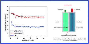
The present work is aimed at investigating the electrochemical properties of Li-ion cells, assembled using lithium substituted polyaniline and its composites with LiFePO4 and LiMn2O4 as the cathode active materials. Lithium substitution in PANI can be achieved by a variety of approaches and the present work introduces one of the cost effective methods using a comparatively cheaper lithium salt, n-butyllithium in hexanes (n-BuLi) as the dopant. X-ray diffraction, FTIR and SEM techniques were used to get the structural and surface morphological details of the Li-substituted PANI (LIPO) samples. Coin cells were assembled in the glove box using LIPO as cathode and lithium metal foil as anode with 1 M LiPF6 in EC[thin space (1/6-em)]:[thin space (1/6-em)]DMC (1[thin space (1/6-em)]:[thin space (1/6-em)]1) as electrolyte. Voltage sweep cyclic voltammetry and charge–discharge cycling were employed to characterize the electrochemical capabilities of the assembled cells. The cells are found to show a maximum discharge capacity of 25.04 mA h g−1 with 99.99% columbic efficiency and have got tremendous cycling stability over 50 cycles. Pouch cells were assembled using LIPO samples as cathode active materials, graphite as anode and gel polymer (poly(ethylene oxide)) as electrolyte. The pouch cells are found to hold the open circuit voltage of 0.6 V (OCV) even when bent up to 90° from the initial state, which provides the first signature of constructional flexibility of these polymer based Li ion cells. Hoping to improve the specific capacity of LIPO based cells, composite cathode materials were synthesized by mixing LIPO samples with LiFePO4 and LiMn2O4 in 9[thin space (1/6-em)]:[thin space (1/6-em)]1 ratio by weight. The cells are found to show a maximum discharge capacity of 37 mA h g−1 with 99.99% columbic efficiency and have got excellent cycling stability over 50 cycles. One of the highlights of these studies is the observation that the inherent Jahn–Teller effect associated with LiMn2O4 cathode material can be eliminated to a great extent by making composites with LIPO samples.

Introduction

The development of conducting polymer based rechargeable Li-ion cells with high specific capacity and excellent cycling characteristics is a highly competitive area among research and development groups, worldwide. Polymer based rechargeable batteries are specifically attractive due to the environmentally benign nature and the possible constructional flexibility they offer. Conducting polymers generally have electronic band structure with π conjugated delocalized electrons spread along the polymer backbone. Conducting and semiconducting polymers have received immense attention since the discovery of high electrical conductivity in doped polyacetylene. In the category of conducting polymers, polyaniline (PANI), polypyrrole (PPY) and polythiophene (PTH) are examples of stable type electrically conducting polymers. Most of the research in the field of conducting polymers has concentrated on their applications in optoelectronic devices like solar cells, light emitting diodes (LED), photoconductors, electrochromic displays and energy storage devices like battery and supercapacitors.1–9

Polymers like PANI, PPY, and PTH are particularly expected to be active electrode materials for lithium secondary battery applications because they are stable in air and have good electrochemical properties. The use of conducting polymers as electrodes in Li-ion cells relies on their electrochemical redox (doping/dedoping) processes. A given polymer can be repeatedly cycled between different oxidation states, thereby acting as a reversible electrode for a rechargeable battery. Although in principle conducting polymers can be used both as anode (by exploiting their reduction or n-doping process) and cathode (by oxidation or p-doping), most battery applications are confined to the latter case. The electrochemical process, in most of the polymer based Li-ion cells, involves the Li-salt to an extent defined by the Li doping level or the extent of the oxidation state reached by the polymer electrode. The Li doping level is proportional to the amount of charge involved and directly related to battery capacity (mA h).10

Another particular feature of conducting polymer based Li-ion cells is that the electrode kinetics is generally controlled by the diffusion of the dopant anions throughout the polymer structure. As expected, the charge–discharge rate of polymer electrodes greatly depends upon the nature (size and charge density) of the dopant anion and the electrode morphology. Therefore, the synthesis conditions of conducting polymers become very important for assuring their capability as electrodes in electrochemical cells. The polymer electrode configuration retains specific advantages such as flexibility in geometry and design, compatibility with the environment and the projected low cost which are factors that make them competitive for small sized, low rate button prototypes for the microelectronics consumer market.11,12 The development of rechargeable battery systems having excellent charge storage capacity, cyclability, environmental friendliness and flexibility has yet to be realized in practice. Rechargeable Li-ion cells employing cathode active materials like LiCoO2, LiMn2O4, LiFePO4 have got remarkable charge storage capacity with least charge leakage when not in use. However, material toxicity, chance of cell explosion and lack of effective cell recycling mechanism pose significant risk factors which are to be addressed seriously. These cells also lack flexibility in their design due to the structural characteristics of the electrode materials.13,14

In the present work, attempts have been made to assemble rechargeable Li ion cells employing Li substituted (Li-doped) polyaniline as the cathode active material, lithium foil as anode and lithium hexafluorophosphate (LiPF6) in ethylene carbonate (EC)[thin space (1/6-em)]:[thin space (1/6-em)]dimethyl carbonate (DMC) (1[thin space (1/6-em)]:[thin space (1/6-em)]1) as electrolyte. In earlier reports, using lithium substituted (lithiated) PANI as cathode, the lithiation has been achieved by treating PANI with LiPF6 or LiBF4.2,15–17 In the present work lithiation has been effected by treating PANI with n-butyllithium (n-BuLi) in hexane which is a novel approach to achieve lithium substitution in PANI. The prime advantage of this technique is the much reduced material cost involved in the synthesis. The cost of n-BuLi is about 1/10th of that of LiPF6 and LiBF4. Structural and morphological studies on Li-substituted PANI, along with the electrochemical characterization have not been carried out extensively. Concentration of n-BuLi has been varied to get Li doped PANI samples with improved specific capacity. However it is observed that the charge storage capacity is not sufficient to meet the current industrial requirements.

Hence with a vision of increasing the charge storage capacity, we have synthesized LIPO–LiFePO4/LiMn2O4 composites by mixing LIPO samples with LiFePO4/LiMn2O4 in 9[thin space (1/6-em)]:[thin space (1/6-em)]1 ratio by weight using a mortar. The resultant products were used as the active material in cathode preparation. The cyclic voltammograms and charge–discharge characteristics of LIPO–LiFePO4/LiMn2O4 composite cathode based coin cells were investigated and their capabilities compared.

Experimental

Synthesis

To start with, the emeraldine salt (ES) form of HCl doped PANI was synthesized via chemical oxidative polymerization method.18 It was de-doped using NH4OH solution to get the emeraldine base (EB) form of PANI. The resultant product was treated with “n-butyllithium in hexanes (n-BuLi)” in an argon filled glove box (99.999% purity) with moisture content less than 5 ppm, to get the lithiated form of PANI. The n-BuLi is expected to disaggregate the polyaniline clusters by binding the amines to its lithium centers and this process is referred to as metalation. Concentration of the n-BuLi was varied in three steps to achieve improved metalation.19 The reaction mechanism is illustrated in Fig. 1. Resultant products are named as LIPO 1, LIPO 2 and LIPO 3 respectively. These samples were subjected to detailed structural characterization. Coin cells were assembled in the glove box using LIPO 1, LIPO 2 and LIPO 3 as cathode active materials, lithium metal foil as anode, porous polyethylene film as separator and 1 M LiPF6 in EC[thin space (1/6-em)]:[thin space (1/6-em)]DMC (1[thin space (1/6-em)]:[thin space (1/6-em)]1) as electrolyte. The charge collector (Al foil), LIPO electrode, separator/electrolyte solution, lithium metal electrode, and charge collector (Al mesh) were assembled in sequence as a sandwich and enveloped in a laminated-stainless steel button type cap (2032) inside an argon filled glove box. The assembled coin cells were characterized to assess the electrochemical capabilities.
image file: c5ra10706g-f1.tif
Fig. 1 Possible mechanism of partial metalation process.

LIPO 1, LIPO 2 and LIPO 3 were used to make composites with LiFePO4/LiMn2O4 in 9[thin space (1/6-em)]:[thin space (1/6-em)]1 proportion by weight. They were named as LiFe 1, LiFe 2 and LiFe 3 and LiMO 1, LiMO 2 and LiMO 3 respectively. LIPO–LiFePO4/LiMn2O4 composites with 10% conductive additives and the PVDF binder were coated on battery grade aluminium foils and dried for 3 h at 60 °C under dynamic vacuum. The electrochemical cells were assembled using LIPO–LiFePO4/LiMn2O4 powder as the active material for the positive electrode as explained earlier.

Characterisations

Thermo Electron IRIS INTREPID II XSP DUO model ICP-AES system was used for the qualitative and quantitative determination of the presence of lithium in the samples. X-ray diffraction (XRD) employing Rigaku Dmax C diffractometer with Cu Kα radiation of 1.54 Å was used for the structural characterization of the samples. A Thermo Nicolete Avatar 370 DTGS model Fourier Transform IR (FTIR) spectrophotometer was used to obtain the IR spectrum of the samples in the range 400–4000 cm−1. JEOL Model JSM-6390LV Scanning Electron Microscope (SEM) was used to generate surface morphological images of the samples with the resolution of a micrometre. Cyclic voltammetry experiment was carried out employing the Biologic SP300 research grade potentiostat/galvanostat. Charge–discharge test was carried out between 2 V and 4 V using 8 channel battery analyser (5 V, 1 mA-MTI Corporation USA) at C/10 current rate.

Results and discussions

Lithiated polyaniline (LIPO)

Inductively coupled plasma atomic emission (ICP-AES) analysis. In this instrument, the atomic spectrum emitted by a sample is used to determine its elemental composition. The wavelength at which emission occurs is used to identify the element, and the intensity of the emitted radiation quantifies its concentration.20 LIPO 1, LIPO 2 and LIPO 3 samples were digested using 5 mL HNO3 and made up into 100 mL using HPLC grade water and were analysed using ICP-AES system. Results of the analysis are tabulated in Table 1. It can be seen that on increasing the n-BuLi concentration, the lithium content in the sample is getting increased. However the metalation is partial and the maximum metalation achieved is 15.39%. The behaviour of Li enrichment with n-BuLi doping concentration is shown in Fig. 2.
Table 1 ICP-AES measurement data
Sample name Lithium content (%)
LIPO 1 10.04
LIPO 2 13.61
LIPO 3 15.39


image file: c5ra10706g-f2.tif
Fig. 2 Variation of lithiation with respect to n-BuLi doping concentration.
X-ray diffraction studies. On studying the powder diffraction data shown in Fig. 3, it is clear that emeraldine base form of PANI shows broad peaks around 2θ values of 11°, 17° and 21° (ref. 21) which agree with the already reported data. For lithiated samples, instead of broad peaks indicating amorphous structure, intense and narrow peaks are seen around 11° and 21° with additional diffraction peaks at 30°, 33°, 37°, 50°. The presence of these peaks indicates a semi crystalline nature for all the lithiated samples. Better crystalline nature of these lithiated PANI samples compared to normal PANI is a good sign of better structural order, which in turn is helpful to sustain the structural integrity during Li ion exchange.
image file: c5ra10706g-f3.tif
Fig. 3 X-ray diffraction patterns of EB PANI and lithiated PANI samples.
FTIR analysis. The IR response of the emeraldine base form of PANI and the lithiated samples is illustrated in Fig. 4. In PANI, the characteristic peaks at 1584 cm−1 and 1497 cm−1 correspond to the quinoid ring (Q) and the benzenenoid ring stretching modes respectively. It can be seen that for lithiated samples, the peak at 1584 cm−1 is broadened enough to be hardly considered as the signature of quinoid stretching. The characteristic peak of polyaniline base is the N[double bond, length as m-dash]Q[double bond, length as m-dash]N stretching band at 1129 cm−1.22 The bands in the range 1200–1400 cm−1 represent the C–N stretching modes of the aromatic ring. For the lithiated samples, vibration modes at 1304 cm−1 and 1497 cm−1 are absent which are of secondary aromatic amine stretching and benzenoid ring stretching respectively. These modes are signatures of the presence of amine and imine groups in the sample. It is seen that on lithiation these modes become very feeble to be detected by the sensor. This is a strong evidence for lithium substitution of PANI although it is partial.
image file: c5ra10706g-f4.tif
Fig. 4 IR transmission curves of EB PANI and lithiated PANI samples.
Microstructure analysis-SEM. The scanning electron microscope images of EB PANI and the three lithiated PANI samples are shown in Fig. 5 and 6 respectively. It is seen that surface morphology is considerably modified at the submicron level on increasing the n-BuLi concentration. For the lowest n-BuLi concentration, rod like structures are formed. For the medium n-BuLi concentration flake like structures are observed and for the highest n-BuLi concentration, the result is the formation of bigger flake like structures. Unlike the random distribution of polymer chains in EB PANI, on treating with n-BuLi, more ordered structures are formed in LIPO 1, LIPO 2 and LIPO 3 samples, complementing the presence of crystalline peaks in the X-ray diffraction patterns of these samples. These ordered structures can comfortably sustain this morphology during Li ion exchange process with a healthy Li ion transport.
image file: c5ra10706g-f5.tif
Fig. 5 SEM image of EB PANI.

image file: c5ra10706g-f6.tif
Fig. 6 SEM images of LIPO 1, LIPO 2 and LIPO 3.
Electrical conductivity studies. The DC electrical conductivity of the samples was studied using two probe technique, employing Keithley source meter, interfaced to a computer using Lab-View program. The current–voltage (IV) curves for different concentrations of n-BuLi, with the calculated conductivity values, are shown in Fig. 7. Conductivity of the samples shows only a marginal increase on treating with n-BuLi. However the conductivity values obtained are in the expected range for cathode active materials.
image file: c5ra10706g-f7.tif
Fig. 7 IV curves of the samples for different n-BuLi concentration along with the calculated conductivity values.
Cyclic voltammetry analysis. The cyclic voltammetry studies were carried out on coin cells assembled in the glove box using lithiated PANI as cathode and Li metal as anode. The cyclic voltammetry curves of the LIPO 1, LIPO 2 and LIPO 3 samples are shown in Fig. 8. The response curves for voltage scan between 2 V to 4 V show reversible characteristics with broad peaks corresponding to cathodic and anodic scans. The cathodic peak corresponds to one step Li oxidation process to form Li deficient PANI with the release of an electron from the cathode. The anodic peak corresponds to the reduction of Li ion with the insertion of Li back into cathode. It is seen that, the oxidation potential is in the range 3.5–4 V and the reduction potential falls between 2.6 V to 3.5 V. The cathodic and anodic peaks become more prominent and resolved as the percentage of lithiation increases. The area of the CV curve also increases with increase in the percentage of lithiation. The open circuit voltage of the assembled coin cells is around 3.5 V.
image file: c5ra10706g-f8.tif
Fig. 8 Voltage sweep cyclic voltammetry response of LIPO 1, LIPO 2 and LIPO 3.
Charge discharge cycle analysis. The theoretical capacity of lithiated polyaniline is 142 mA h g−1 which corresponds to 100% lithiation.23 In the present work, maximum lithiation achieved is only 15%. Hence the theoretical capacity expected is around 25 mA h g−1. The maximum specific capacity of 25.04 mA h g−1 is obtained for LIPO 3 sample with the maximum Li substitution around 15%. Lithiated PANI based Li-ion cells with fairly good specific capacity close to theoretical capacity, columbic efficiency close to 100% and excellent cycling stability have not been reported earlier. In the present case, LIPO 3 sample shows the maximum capacity of 25.04 mA h g−1 for the first cycle and then shows a decreasing nature for a few following cycles. After the fifth cycle onwards, the capacity remains the same up to the 50th cycle. In the case of the other two samples, for the first few cycles, a capacity in the range 13–16.5 mA h g−1 is observed and thereafter there is a fall in capacity till the 10th cycle. Then the capacity shows no fading for the rest of the cycles until the 50th. The charge–discharge curves of the three cells are shown in Fig. 9 and the specific capacities are plotted in Fig. 10.
image file: c5ra10706g-f9.tif
Fig. 9 Charge–discharge curves of LIPO 1, LIPO 2 and LIPO 3.

image file: c5ra10706g-f10.tif
Fig. 10 Specific capacity versus charge–discharge cycle number for LIPO 1, LIPO 2 and LIPO 3.

After the 5th and 10th charge discharge cycles, all the three samples show a stable cycling behaviour. All the three samples show columbic efficiency close to 99% for all the charge discharge cycles.

Pouch cells were assembled using LIPO samples as cathode, graphite as anode24 and gel polymer (poly(ethylene oxide)) as electrolyte.25,26 Schematic diagrams of the assembled cells are shown in Fig. 11 and the realised pouch cell is shown in Fig. 12. The pouch cells are found to hold the open circuit voltage of 0.6 V (OCV) even when they are bent up to 90° from the initial state. This gives the first signature of flexibility associated with polymer based Li-ion cells.


image file: c5ra10706g-f11.tif
Fig. 11 Schematic representation of pouch cells assembled with LIPO 1, LIPO 2 and LIPO 3.

image file: c5ra10706g-f12.tif
Fig. 12 Pouch cell assembled with LIPO 1, LIPO 2 and LIPO 3.

Lithiated-polyaniline–LiFePO4 composite (LiFe)

X-ray diffraction study. X-ray diffraction patterns of LIPO–LiFePO4 composite samples are shown in Fig. 13. The patterns consist of the characteristics peaks of both lithiated PANI and LiFePO4. Characteristic peaks of LIPO are well evident from the XRD patterns. There are also peaks corresponding to 20° (101), 25° (201, 111), 30° (211, 020) and 35° (311) which give the clear evidence for the presence of LiFePO4 in the composite system.27
image file: c5ra10706g-f13.tif
Fig. 13 The XRD spectrum of EB PANI, LiFe 1, LiFe 2 and LiFe 3.
Cyclic voltammetry studies. In order to identify oxidation/reduction potentials and study the electrochemical capability of the cells assembled using LiFe composite cathodes, cyclic voltammetry was performed. The oxidation and reduction peaks of these systems occur within 2 to 4 V and show good reversibility. For these LiFe cells, the upper two broad peaks (∼3.32 and ∼3.7 V) correspond to the oxidation and the lower two broad peaks (∼2.82, and ∼2.41 V) to the reduction as shown in Fig. 14. There are two broad peaks in oxidation stage and two broad peaks in reduction stage for LiFe systems. The upper peak at ∼3.32 V corresponds to the oxidation of Li in lithiated PANI and that at 3.7 V to the oxidation (de-intercalation of Li+ ion) of Li in LiFePO4 and the lower peaks at ∼2.82 and ∼2.18 V correspond to the reduction of LIPO and that (intercalation of Li+ ion) of LiFePO4 respectively.12
image file: c5ra10706g-f14.tif
Fig. 14 Cyclic voltammograms of LIPO, LiFe 1, LiFe 2 and LiFe 3.
Charge discharge analysis. The discharge characteristics of LiFe 1, LiFe 2 and LiFe 3 cells are shown in Fig. 15. These discharge curves resemble those of transition metal oxide electrodes in conventional rechargeable lithium ion cells. The average operating voltage of these cells may be approximated to 3.3 V in spite of different LIPOs used. The plots showing the variation of discharge capacity of LiFe (1–3) samples with number of cycles are shown in Fig. 16. The highest discharge capacity is around 40 mA h g−1 for LiFe 3 followed by 25 mA h g−1 for LiFe 2 and 21 mA h g−1 for LiFe 1.
image file: c5ra10706g-f15.tif
Fig. 15 Charge–discharge curves of LIPO, LiFe 1, LiFe 2 and LiFe 3 cells.

image file: c5ra10706g-f16.tif
Fig. 16 Discharge capacity against cycle number curves of LiFe 1, LiFe 2 and LiFe 3 cells.

The variation of charge efficiency with cycle number of the assembled coin cells is shown in Fig. 17. All the cells show an average efficiency around 98%. The observed values are very impressive and can be compared with those of the conventional Li-ion secondary battery systems.


image file: c5ra10706g-f17.tif
Fig. 17 Charge efficiency against cycle number curves of LiFe 1, LiFe 2 and LiFe 3 cells.

Lithiated-polyaniline–LiMn2O4 composite (LiMO)

X-ray diffraction study. X-ray diffraction patterns of LIPO–LiMn2O4 composite samples are depicted in Fig. 18 and they consist of the characteristic peaks of both lithiated PANI and LiMn2O4. Major peaks of LiMn2O4 at 20° (111), 36° (311), 45° (400), 59° (511) are present in the XRD patterns. Generally on cycling, LiMn2O4 which has spinel structure, slowly gets transformed to the tetragonal phase compound, leading to poor cyclability of the electrode. This drawback, its inability to sustain the charge capacity over the charge discharge cycles, due to Jahn–Teller effect may be overcome by mixing LiMn2O4 with suitable Li-containing conducting polymer based materials.28
image file: c5ra10706g-f18.tif
Fig. 18 X-ray diffraction patterns of EB PANI, LiMO 1, LiMO 2 and LiMO 3.

image file: c5ra10706g-f19.tif
Fig. 19 Cyclic voltammograms of LIPO, LiMO 1, LiMO 2 and LiMO 3.
Cyclic voltammetry. The cyclic voltammograms of LIPO and LiMO (1–3) cells in the range 2–4 V are shown in Fig. 19. The oxidation and reduction peaks of these cells occur within 2 to 4 V and show good reversibility. The upper broad peak at ∼3.5 V is common to both LIPO and LiMn2O4 which corresponds to the oxidation of Li in lithiated PANI and that (de-intercalation of Li+ ion) in LiMn2O4. The lower broad peak at ∼2.32 V is also common to both LIPO and LiMn2O4 which corresponds to the reduction in these components of the composite systems.
Charge discharge characteristics. The discharge characteristics of LiMO 1, LiMO 2 and LiMO 3 based cells are shown in Fig. 20. These discharge curves also resemble those of transition metal oxide electrodes in conventional rechargeable lithium ion cells. The operating voltages of these cells can be approximated to 3.0 V in spite of different LIPOs used. The plots of discharge capacity against number of cycles of LiMO (1–3) cells are shown in Fig. 21. The highest discharge capacity is around 37 mA h g−1 for LiMO 3 based cell, followed by 20 mA h g−1 for LiMO 2 and 10 mA h g−1 for LiMO 1 based cells respectively. For all the cells assembled, the cycling stability over the first fifty cycles is quite remarkable and there is hardly any capacity loss. This could be the result of the nullifying of the Jahn–Teller distortion in LiMn2O4 due to the presence of lithiated PANI in the cathode material.
image file: c5ra10706g-f20.tif
Fig. 20 Charge–discharge curves of LiMO 1, LiMO 2 and LiMO 3 cells.

image file: c5ra10706g-f21.tif
Fig. 21 Discharge capacity against cycle number curves of LiMO 1, LiMO 2 and LiMO 3 cells.

The charge efficiency plots of assembled coin cells are shown in Fig. 22. It is seen that the efficiency of the cells show an increasing tendency till the 10th cycle. There after the efficiency of the cells stabilizes to a fixed value around 98%.


image file: c5ra10706g-f22.tif
Fig. 22 Charge efficiency against cycle number curves of LiMO 1, LiMO 2 and LiMO 3 cells.

Conclusions

The present work highlights the suitability of using n-butyllithium, a cost effective substitute for expensive counterparts like LiPF6 and LiBF4, for synthesizing Li substituted polyaniline to be used as the cathode active material in rechargeable Li ion cells. The structural analysis confirms the enhanced crystallinity/order in Li substituted samples compared to pure PANI. The coin cells assembled using Li substituted PANI as cathode show quite good electrochemical behaviour. Specific capacity close to the expected theoretical capacity has been obtained for all the cells fabricated. All the three assembled cells show excellent columbic efficiency around 99% and stable charge discharge cycling behaviour up to 50 cycles. The pouch cells assembled using lithiated PANI as cathode are found to hold the open circuit voltage (OCV) even when bent up to 90° from the initial state. This will open up a new methodology to fabricate all solid state, flexible and environmentally friendly lithium ion cells. However, the capacity of the lithiated PANI based cells have to be improved still further to meet the current industrial standards. For that, lithiated PANI (LIPO 1, LIPO 2 and LIPO 3)–LiFePO4/LiMn2O4 (9[thin space (1/6-em)]:[thin space (1/6-em)]1 ratio) composite electrodes based Li-ion cells were assembled and detailed electrochemical characterization was carried out. The cells assembled with LIPO 3–LiFePO4/LiMn2O4 composites as active electrodes show dominant electrochemical characteristics over LIPO 1–LiFePO4/LiMn2O4 and LIPO 2–LiFePO4/LiMn2O4 based cells. The average voltage of these cells is around 3.3 V. The cells are having the highest discharge capacity around 40 mA h g−1 and columbic efficiency around 97% and have got tremendous capacity retention over 50 cycles. Unlike pure LiMn2O4 based cells with poor cyclability due to Jahn–Teller distortion, LiMO cells have been found to overcome this distortion effect and show healthy cycling stability, due to the presence of lithiated PANI in the cathode material. The present work highlights a novel but simple approach to nullify the Jahn–Teller distortion in LiMn2O4 by properly mixing it with lithiated PANI to function as the cathode. On optimizing the n-BuLi doping concentration and LIPO–LiFePO4/LiMn2O4 mixing ratios, polymer based Li-ion hybrid cells having promising energy density, capacity and eco friendliness with structural flexibility can be realized.

Acknowledgements

The financial assistance provided by the Board of Research in Nuclear Sciences (BRNS), Government of India, is gratefully acknowledged.

References

  1. T. Ito, H. Shirakawa and S. Ikeda, J. Polym. Sci., Polym. Chem. Ed., 1974, 12, 11 CrossRef CAS PubMed.
  2. P. J. Nigrey, D. Maclnnes Jr, D. P. Nairns and A. J. MacDiarmid, J. Electrochem. Soc., 1981, 128(8), 1651 CrossRef CAS PubMed.
  3. S. Panero, P. Prosperi, F. Bonino, B. Scrosati, A. Corradini and M. Mastragostino, Electrochim. Acta, 1987, 32(7), 1007 CrossRef CAS.
  4. K. Nishio, M. Fujimoto, N. Yoshinaga, N. Furukawa, O. Ando, H. Ono and T. Suzuki, J. Power Sources, 1991, 34, 153 CrossRef CAS.
  5. R. D. Loufty and J. H. Sharp, J. Chem. Phys., 1979, 71(3), 1211 CrossRef PubMed.
  6. B. P. Jelle, G. Hagen and S. Nodland, Electrochim. Acta, 1993, 38(11), 1497 CrossRef CAS.
  7. Z. Bao, Y. Feng, A. Dodabalpu, V. R. Raju and A. J. Lovinger, Chem. Mater., 1997, 9(6), 1299 CrossRef CAS.
  8. M. E. Abdelhamid, A. P. O'Mullane and G. A. Snook, RSC Adv., 2015, 5, 11611–11626 RSC.
  9. P. Sengodu and A. D. Deshmukh, RSC Adv., 2015, 5, 42109–42130 RSC.
  10. C. Arbizzani, M. Mastragostino and B. Scrosati, Handbook of Organic Conductive Molecules and Polymers, ed. H. S. Nalwa, John Wiley & Sons Ltd, 1997, ch. 11 Search PubMed.
  11. T. Osaka, K. Naoi and S. Ogano, J. Electrochem. Soc., 1988, 135(5), 1071 CrossRef CAS PubMed.
  12. K. S. Ryu, et al., Bull. Korean Chem. Soc., 2002, 23, 8 Search PubMed.
  13. M. Yoshio, R. J. Brodd and A. Kozawa, Lithium-Ion Batteries, Science and Technologies, Springer XXVI., 2009, vol. 452, p. 279 Search PubMed.
  14. B. Xu, D. Qian, Z. Wang and Y. S. Meng, Mater. Sci. Eng., 2001, 73(2), 51–65 Search PubMed.
  15. S. Panero, P. Prosperi, F. Bonino, B. Scrosati, A. Corradini and M. Mastragostino, Electrochim. Acta, 1987, 32(7), 1007 CrossRef CAS.
  16. K. Nishio, M. Fujimoto, N. Yoshinaga, N. Furukawa, O. Ando, H. Ono and T. Suzuki, J. Power Sources, 1991, 34, 153 CrossRef CAS.
  17. K. S. Ryu, et al., Synth. Met., 2000, 110, 213–217 CrossRef CAS.
  18. I. Sapurina and J. Stejskal, Polym. Int., 2008, 57, 1295–1325 CrossRef CAS PubMed.
  19. M. A. Miah and V. Snieckus, J. Org. Chem., 1985, 50, 5436 CrossRef CAS.
  20. T. J. Manning and W. R. Grow, The chemical educator, Springer-Verlag S., 1997; pp. 1430–4171 Search PubMed.
  21. A. Mani, K. Athinarayanasamy, P. Kamaraj, S. T. Selvan, S. Ravichandran, K. L. N. Phani and S. Pitchumani, J. Mater. Sci. Lett., 1995, 14(22), 1594–1596 CrossRef CAS.
  22. M. Trchova and J. Stejskal, Pure Appl. Chem., 2011, 83, 1803–1817 CrossRef CAS.
  23. K. S. Ryu and K. M. Kim, J. Power Sources, 2007, 165, 420–426 CrossRef CAS PubMed.
  24. C. P. Sandhya, B. John and C. Gouri, Ionics, 2014, 20, 601–620 CrossRef CAS.
  25. J. Y. Song, Y. Y. Wang and C. C. Wan, J. Power Sources, 1999, 77, 183–197 CrossRef CAS.
  26. A. B. Puthirath, B. John, C. Gouri and S. Jayalekshmi, Ionics, 2015, 21, 2185–2191 CrossRef CAS.
  27. L. Lin, Y. Wen, O. Junke, Y. Guo and D. Xiao, RSC Adv., 2013, 3, 14652–14660 RSC.
  28. R. M. Tomy, K. M. A. Kumar, P. B. Anand and S. Jayalekshmi, J. Phys. Chem. Solids, 2011, 72, 1251–1255 CrossRef CAS PubMed.

This journal is © The Royal Society of Chemistry 2015
Click here to see how this site uses Cookies. View our privacy policy here.